Note: Descriptions are shown in the official language in which they were submitted.
CARBON COMPOSITES COMPRISING CARBON MICROSTRUCTURES
BACKGROUND
[0001-2] Graphite is an allotrope of carbon and has a layered, planar
structure. In
each layer, the carbon atoms are arranged in hexagonal arrays or networks
through covalent
bonds. Different carbon layers however are held together only by weak van der
Waals forces.
[0003] Graphite has been used in a variety of applications including
electronics,
atomic energy, hot metal processing, coatings, aerospace and the like due to
its excellent thermal
and electrical conductivities, lightness, low friction, and high heat and
corrosion resistances.
However, graphite is not elastic and has low strength, which may limit its
further applications.
Thus, the industry is always receptive to new graphite materials having
improved elasticity and
mechanical strength. It would be a further advantage if such materials also
have improved high
temperature corrosion resistance.
BRIEF DESCRIPTION
[0004] The above and other deficiencies in the prior art are be
overcome by, in an
embodiment, a carbon composite comprising: carbon microstructures having
interstitial space
among the carbon microstructures, the carbon microstructures having an aspect
ratio of 10 to 500
and being substantially parallel to each other; and a binder disposed in at
least some of the
interstitial space, wherein the carbon microstructures comprise unfilled voids
within the carbon
microstructures.
[0005] In another embodiment, a carbon composite comprises: at least
two carbon
microstructures, the carbon microstructures having an aspect ratio of 10 to
500 and being
substantially parallel to each other; and a binding phase disposed between the
at least two carbon
microstructures, wherein the binding phase includes a binder comprising one or
more of the
following: SiO2; Si; B; B201; a metal; and an alloy of the metal and wherein
the metal is one or
more of the following: aluminum; copper; titanium; nickel; tungsten; chromium;
iron; manganese;
zirconium; hafnium; vanadium; niobium; molybdenum; tin; bismuth; antimony;
lead; cadmium;
and selenium..
[0006] The composites can be in the form of a bar, block, sheet,
tubular, cylindrical
billet, toroid, powder, or pellets.
1
CA 2961167 2018-08-08
CA 02961167 2017-03-13
WO 2016/043876 PCT/US2015/044950
BRIEF DESCRIPTION OF THE DRAWINGS
[0007] The following descriptions should not be considered limiting in
any way.
With reference to the accompanying drawings, like elements are numbered alike:
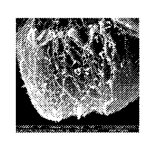
[0008] FIG. 1 is a scanning electron microscopic ("SEM") image of a
composition containing expanded graphite and a micro- or nano-sized binder
blended at room
temperature and atmospheric pressure;
[0009] FIG. 2 is a SEM image of a carbon composite formed from expanded
graphite and a micro- or nano-sized binder under high pressure and high
temperature
conditions according to one embodiment of the disclosure;
[0010] FIG. 3 is a SEM image of carbon microstructures according to
another
embodiment of the disclosure;
[0011] FIG. 4 is a schematic illustration of a carbon composite
according to an
embodiment of the disclosure;
[0012] FIG. 5 shows stress-strain curves of (A) natural graphite; (B)
expanded
graphite; (C) a mixture of expanded graphite and a micro- or nano-sized
binder, where the
sample is compacted at room temperature and high pressure; (D) a carbon
composite
according to one embodiment of the disclosure compacted from a mixture of
expanded
graphite and a micro- or nano-sized binder at a high temperature and a low
pressure (also
referred to as "soft composite"); and (E) a carbon composite according to
another
embodiment of the disclosure formed from expanded graphite and a micro- and
nano-sized
binder under high pressure and high temperature conditions (also referred to
as "hard
composite");
[0013] FIG. 6 shows loop test results of a carbon composite at different
loadings;
[0014] FIG. 7 shows hysteresis results of a carbon composite tested at
room
temperature and 500 F respectively;
[0015] FIG. 8 compares a carbon composite before and after exposing to
air at
500 C for 25 hours;
[0016] FIG. 9 (A) is a photo of a carbon composite after a thermal
shock; FIG. 9
(B) illustrates the condition for the thermal shock;
[0017] FIG. 10 compares a carbon composite sample (A) before and (B)
after
exposing to tap water for 20 hours at 200 F, or (C) after exposing to tap
water for 3 days at
200 F;
2
CA 02961167 2017-03-13
WO 2016/043876
PCT/US2015/044950
[0018] FIG. 11 compares a carbon composite sample (A) before and (B)
after
exposing to 15% HC1 solution with inhibitor at 200 F for 20 hours, or (C)
after exposing to
15% HCI solution at 200 F for 3 days; and
[0019] FIG. 12 shows the sealing force relaxation test results of a
carbon
composite at 600 F.
DETAILED DESCRIPTION
[0020] The inventors hereof have found that carbon composites formed
from
graphite and micro- or nano-sized binders at high temperatures have improved
balanced
properties as compared to graphite alone, a composition formed from the same
graphite but
different binders, or a mixture of the same graphite and the same binder
blended at room
temperature under atmospheric pressure or high pressures. The new carbon
composites have
excellent elasticity. In addition, the carbon composites have excellent
mechanical strength,
heat resistance, and chemical resistance at high temperatures. In a further
advantageous
feature, the composites keep various superior properties of the graphite such
as heat
conductivity, electrical conductivity, lubricity, and the alike.
[0021] Without wishing to be bound by theory, it is believed that the
improvement in mechanical strength is provided by a binding phase disposed
between carbon
microstructures. There are either no forces or only weak Van der Waals forces
exist between
the carbon microstructures, thus the graphite bulk materials have weak
mechanical strength.
At high temperatures, the micro- and nano-sized binder liquefies and is
dispersed evenly
among carbon microstructures. Upon cooling, the binder solidifies and forms a
binding
phase binding the carbon nanostructures together through mechanical
interlocking.
[0022] Further without wishing to be bound by theory, for the composites
having
both improved mechanical strength and improved elasticity, it is believed that
the carbon
microstructures themselves are laminar structures having spaces between the
stacked layers.
The binder only selectively locks the microstructures at their boundaries
without penetrating
the microstructures. Thus the unbounded layers within the microstructures
provide elasticity
and the binding phase disposed between the carbon microstructures provides
mechanical
strength.
[0023] The carbon microstructures are microscopic structures of graphite
formed
after compressing graphite into highly condensed state. They comprise graphite
basal planes
stacked together along the compression direction. As used herein, carbon basal
planes refer
to substantially flat, parallel sheets or layers of carbon atoms, where each
sheet or layer has a
3
CA 02961167 2017-03-13
WO 2016/043876
PCT/US2015/044950
single atom thickness. The graphite basal planes are also referred to as
carbon layers. The
carbon microstructures are generally flat and thin. They can have different
shapes and can
also be referred to as micro-flakes, micro-discs and the like. In an
embodiment, the carbon
microstructures are substantially parallel to each other.
[0024] There are two types of voids in the carbon composites - voids or
interstitial
spaces between carbon microstructures and voids within each individual carbon
microstructures. The interstitial spaces between the carbon microstructures
have a size of
about 0.1 to about 100 microns, specifically about 1 to about 20 microns
whereas the voids
within the carbon microstructures are much smaller and are generally between
about 20
nanometers to about 1 micron, specifically about 200 nanometers to about 1
micron. The
shape of the voids or interstitial spaces is not particularly limited. As used
herein, the size of
the voids or interstitial spaces refers to the largest dimension of the voids
or interstitial spaces
and can be determined by high resolution electron or atomic force microscope
technology.
[0025] The interstitial spaces between the carbon microstructures are
filled with a
micro- or nano-sized binder. For example, a binder can occupy about 10 % to
about 90 % of
the interstitial spaces between the carbon microstructures. However, the
binder does not
penetrate the individual carbon microstructures and the voids within carbon
microstructures
are unfilled, i.e., not filled with any binder. Thus the carbon layers within
the carbon
microstructures are not locked together by a binder. Through this mechanism,
the flexibility
of the carbon composite, particularly, expanded carbon composite can be
preserved.
[0026] The carbon microstructures have a thickness of about 1 to about
200
microns, about 1 to about 150 microns, about 1 to about 100 microns, about 1
to about 50
microns, or about 10 to about 20 microns. The diameter or largest dimension of
the carbon
microstructures is about 5 to about 500 microns or about 10 to about 500
microns. The
aspect ratio of the carbon microstructures can be about 10 to about 500, about
20 to about
400, or about 25 to about 350. In an embodiment, the distance between the
carbon layers in
the carbon microstructures is about 0.3 nanometers to about I micron. The
carbon
microstructures can have a density of about 0.5 to about 3 g/cm3, or about 0.1
to about 2
g/cm3.
[0027] As used herein, graphite includes natural graphite, synthetic
graphite,
expandable graphite, expanded graphite, or a combination comprising at least
one of the
foregoing. Natural graphite is graphite formed by Nature. It can be classified
as "flake"
graphite, "vein" graphite, and "amorphous" graphite. Synthetic graphite is a
manufactured
product made from carbon materials. Pyrolytic graphite is one form of the
synthetic graphite.
4
CA 02961167 2017-03-13
WO 2016/043876 PCT/US2015/044950
Expandable graphite refers to graphite having intercallant materials inserted
between layers
of natural graphite or synthetic graphite. A wide variety of chemicals have
been used to
intercalate graphite materials. These include acids, oxidants, halides, or the
like. Exemplary
intercallant materials include sulfuric acid, nitric acid, chromic acid, boric
acid, SO3, or
halides such as FeC13, ZnC12, and SbC15. Upon heating, the intercallant is
converted from a
liquid or solid state to a gas phase. Gas formation generates pressure which
pushes adjacent
carbon layers apart resulting in expanded graphite. The expanded graphite
particles are
vermiform in appearance, and are therefore commonly referred to as worms.
[0028] Advantageously, the carbon composites comprise expanded graphite
microstructures. Compared with other forms of the graphite, expanded graphite
has high
flexibility and compression recovery, and larger anisotropy. The composites
formed from
expanded graphite and micro- or nano-sized binder under high pressure and high
temperature
conditions can thus have excellent elasticity in addition to desirable
mechanical strength.
[0029] In the carbon composites, the carbon microstructures are held
together by a
binding phase. The binding phase comprises a binder which binds carbon
microstructures by
mechanical interlocking. Optionally, an interface layer is formed between the
binder and the
carbon microstructures. The interface layer can comprise chemical bonds, solid
solutions, or
a combination thereof. When present, the chemical bonds, solid solutions, or a
combination
thereof may strengthen the interlocking of the carbon microstructures. It is
appreciated that
the carbon microstructures may be held together by both mechanical
interlocking and
chemical bonding. For example the chemical bonding, solid solution, or a
combination
thereof may be formed between some carbon microstructures and the binder or
for a
particular carbon microstructure only between a portion of the carbon on the
surface of the
carbon microstructure and the binder. For the carbon microstructures or
portions of the
carbon microstructures that do not form a chemical bond, solid solution, or a
combination
thereof, the carbon microstructures can be bounded by mechanical interlocking.
The
thickness of the binding phase is about 0.1 to about 100 microns or about Ito
about 20
microns. The binding phase can form a continuous or discontinuous network that
binds
carbon microstructures together.
[0030] Exemplary binders include SiO2, Si, B, B203, a metal, an alloy,
or a
combination comprising at least one of the foregoing. The metal can be
aluminum, copper,
titanium, nickel, tungsten, chromium, iron, manganese, zirconium, hafnium,
vanadium,
niobium, molybdenum, tin, bismuth, antimony, lead, cadmium, and selenium. The
alloy
includes the alloys of aluminum, copper, titanium, nickel, tungsten, chromium,
iron,
CA 02961167 2017-03-13
WO 2016/043876
PCT/US2015/044950
manganese, zirconium, hafnium, vanadium, niobium, molybdenum, tin, bismuth,
antimony,
lead, cadmium, and selenium. In an embodiment, the binder comprises copper,
nickel,
chromium, iron, titanium, an alloy of copper, an alloy of nickel, an alloy of
chromium, an
alloy of iron, an alloy of titanium, or a combination comprising at least one
of the foregoing
metal or metal alloy. Exemplary alloys include steel, nickel-chromium based
alloys such as
Inconel*, and nickel-copper based alloys such as Monel alloys. Nickel-chromium
based
alloys can contain about 40-75% of Ni, about 10-35% of Cr. The nickel-chromium
based
alloys can also contain about 1 to about 15% of iron. Small amounts of Mo, Nb,
Co, Mn, Cu,
Al, Ti, Si, C, S, P, B, or a combination comprising at least one of the
foregoing can also be
included in the nickel-chromium based alloys. Nickel-copper based alloys are
primarily
composed of nickel (up to about 67%) and copper. The nickel-copper based
alloys can also
contain small amounts of iron, manganese, carbon, and silicon. These materials
can be in
different shapes, such as particles, fibers, and wires. Combinations of the
materials can be
used.
[0031] The binder used to make the carbon composite is micro- or nano-
sized. In
an embodiment, the binder has an average particle size of about 0.05 to about
10 microns,
specifically, about 0.5 to about 5 microns, more specifically about 0.1 to
about 3 microns.
Without wishing to be bound by theory, it is believed that when the binder has
a size within
these ranges, it disperses uniformly among the carbon microstructures.
[0032] When an interface layer is present, the binding phase comprises a
binder
layer comprising a binder and an interface layer bonding one of the at least
two carbon
microstructures to the binder layer. In an embodiment, the binding phase
comprises a binder
layer, a first interface layer bonding one of the carbon microstructures to
the binder layer, and
a second interface layer bonding the other of the microstructures to the
binder layer. The first
interface layer and the second interface layer can have the same or different
compositions.
[0033] The interface layer comprises a C-metal bond, a C-B bond, a C-Si
bond, a
C-0-Si bond, a C-0-metal bond, a metal carbon solution, or a combination
comprising at
least one of the foregoing. The bonds are formed from the carbon on the
surface of the
carbon microstructures and the binder.
[0034] In an embodiment, the interface layer comprises carbides of the
binder.
The carbides include carbides of aluminum, titanium, nickel, tungsten,
chromium, iron,
manganese, zirconium, hafnium, vanadium, niobium, molybdenum, or a combination
comprising at least one of the foregoing. These carbides are formed by
reacting the
corresponding metal or metal alloy binder with the carbon atoms of the carbon
6
CA 02961167 2017-03-13
WO 2016/043876 PCT/US2015/044950
microstructures. The binding phase can also comprise SiC formed by reacting
SiO2 or Si
with the carbon of carbon microstructures, or RIC formed by reacting B or B203
with the
carbon of the carbon microstructures. When a combination of binder materials
is used, the
interface layer can comprise a combination of these carbides. The carbides can
be salt-like
carbides such as aluminum carbide, covalent carbides such as SiC, RIC,
interstitial carbides
such as carbides of the group 4, 5, and 5 transition metals, or intermediate
transition metal
carbides, for example the carbides of Cr, Mn, Fe, Co, and Ni.
[0035] In another embodiment, the interface layer comprises a solid
solution of
carbon and the binder. Carbon have solubility in certain metal matrix or at
certain
temperature range, which helps both wetting and binding of metal phase onto
carbon
microstructures. Through heat-treatment, high solubility of carbon in metal
can be maintained
at low temperature. These metals include Co, Fe, La, Mn, Ni, or Cu. The binder
layer can
also comprises a combination of solid solutions and carbides.
[0036] The carbon composites comprise about 20 to about 95 wt. %, about
20 to
about 80 wt. %, or about 50 to about 80 wt. % of carbon, based on the total
weight of the
composites. The binder is present in an amount of about 5 wt. % to about 75
wt. % or about
20 wt. % to about 50 wt. %, based on the total weight of the composites. In
the carbon
composites, the weight ratio of carbon relative to the binding is about 1:4 to
about 20:1, or
about 1:4 to about 4:1, or about 1:1 to about 4:1.
[0037] FIG. 1 is a SEM image of a composition containing expanded
graphite and
a micro- or nano-sized binder blended at room temperature and atmospheric
pressure. As
shown in FIG. 1, the binder (white area) is only deposited on the surface of
some of the
expanded graphite worms.
[0038] FIG. 2 is a SEM image of a carbon composite formed from expanded
graphite and a micro- or nano-sized binder under high pressure and high
temperature
conditions. As shown in FIG. 2, a binding phase (light area) is evenly
distributed between
the expanded graphite microstructures (dark area).
[0039] A SEM image of carbon graphite microstructures are shown in FIG.
3. An
embodiment of a carbon composite is illustrated in Fig 4. As shown in FIG. 4,
the composite
comprises carbon microstructures 1 and binding phase 2 locking the carbon
microstructures.
The binding phase 2 comprises binder layer 3 and an optional interface layer 4
disposed
between the binder layer and the carbon microstructures. The carbon composite
contains
interstitial space 5 among carbon microstructures 1. Within carbon
microstructures, there are
unfilled voids 6.
7
CA 02961167 2017-03-13
WO 2016/043876 PCT/US2015/044950
[0040] The carbon composites can optionally comprise a filler. Exemplary
filler
includes carbon fibers, carbon black, mica, clay, glass fiber, ceramic fibers,
and ceramic
hollow structures. Ceramic materials include SiC, Si3N4, SiO2, BN, and the
like. The filler
can be present in an amount of about 0.5 to about 10 wt. % or about 1 to about
8%.
[0041] The composites can have any desired shape including a bar, block,
sheet,
tubular, cylindrical billet, toroid, powder, pellets, or other form that may
be machined,
formed or otherwise used to form useful articles of manufacture. The sizes or
the dimension
of these forms are not particularly limited. Illustratively, the sheet has a
thickness of about 10
gm to about 10 cm and a width of about 10 mm to about 2 m. The powder
comprises
particles having an average size of about 10 gm to about 1 cm. The pellets
comprise particles
having an average size of about 1 cm to about 5 cm.
[0042] One way to form the carbon composites is to compress a
combination
comprising carbon and a micro- or nano-sized binder to provide a green compact
by cold
pressing; and to compressing and heating the green compact thereby forming the
carbon
composites. In another embodiment, the combination can be pressed at room
temperature to
form a compact, and then the compact is heated at atmospheric pressure to form
the carbon
composite. These processes can be referred to as two-step processes.
Alternatively, a
combination comprising carbon and a micro- or nano-sized binder can be
compressed and
heated directly to form the carbon composites. The process can be referred to
as a one-step
process.
[0043] In the combination, the carbon such as graphite is present in an
amount of
about 20 wt.% to about 95 wt.%, about 20 wt.% to about 80 wt%, or about 50
wt.% to about
80 wt.%, based on the total weight of the combination. The binder is present
in an amount of
about 5 wt. % to about 75 wt. % or about 20 wt. % to about 50 wt. %, based on
the total
weight of the combination. The graphite in the combination can be in the form
of chip,
powder, platelet, flake, or the like. In an embodiment, the graphite is in the
form of flakes
having a diameter of about 50 microns to about 5,000 microns, preferably about
100 to about
300 microns. The graphite flakes can have a thickness of about 1 to about 5
microns. The
density of the combination is about 0.01 to about 0.05 g/cm3, about 0.01 to
about 0.04 g/cm3,
about 0.01 to about 0.03 g/cm3 or about 0.026 g/cm3. The combination can be
formed by
blending the graphite and the micro- or nano-sized binder via any suitable
methods known in
the art. Examples of suitable methods include ball mixing, acoustic mixing,
ribbon blending,
vertical screw mixing, and V-blending.
8
CA 02961167 2017-03-13
WO 2016/043876 PCT/US2015/044950
[0044] Referring to the two-step process, cold pressing means that the
combination comprising the graphite and the micro-sized or nano-sized binder
is compressed
at room temperature or at an elevated temperature as long as the binder does
not significantly
bond with the graphite microstructures. In an embodiment, greater than about
80 wt.%,
greater than about 85 wt.%, greater than about 90 wt.%, greater than about 95
wt.%, or
greater than about 99 wt.% of the microstructures are not bonded in the green
compact. The
pressure to form the green compact can be about 500 psi to about 10 ksi and
the temperature
can be about 20 C to about 200 C. The reduction ratio at this stage, i.e., the
volume of the
green compact relative to the volume of the combination, is about 40% to about
80%. The
density of the green compact is about 0.1 to about 5 g/cm3, about 0.5 to about
3 g/cm3, or
about 0.5 to about 2 g/cm3.
[0045] The green compact can be heated at a temperature of about 350 C
to about
1200 C, specifically about 800 C to about 1200 C to form the carbon
composites. In an
embodiment, the temperature is above the melting point of the binder, for
example, about
20 C to about 100 C higher or about 20 C to about 50 C higher than the melting
point of the
binder. When the temperature is higher, the binder becomes less viscose and
flows better,
and less pressure may be required in order for the binder to be evenly
distributed in the voids
between the carbon microstructures. However, if the temperature is too high,
it may have
detrimental effects to the instrument.
[0046] The temperature can be applied according to a predetermined
temperature
schedule or ramp rate. The means of heating is not particularly limited.
Exemplary heating
methods include direct current (DC) heating, induction heating, microwave
heating, and
spark plasma sintering (SPS). In an embodiment, the heating is conducted via
DC heating.
For example, the combination comprising the graphite and the micro- or nano-
sized binder
can be charged with a current, which flows through the combination generating
heat very
quickly. Optionally, the heating can also be conducted under an inert
atmosphere, for
example, under argon or nitrogen. In an embodiment, the green compact is
heated in the
presence of air.
[0047] The heating can be conducted at a pressure of about 500 psi to
about
30,000 psi or about 1000 psi to about 5000 psi. The pressure can be a
superatmospheric
pressure or a subatmospheric pressure. Without wishing to be bound by theory,
it is believed
that when a superatmospheric pressure is applied to the combination, the micro-
or nano-
sized binder is forced into the voids between carbon microstructures through
infiltration.
When a subatmospheric pressure is applied to the combination, the micro- or
nano-sized
9
CA 02961167 2017-03-13
WO 2016/043876 PCT/US2015/044950
binder can also be forced into the voids between the carbon microstructures by
capillary
forces.
[0048] In an embodiment, the desirable pressure to form the carbon
composites is
not applied all at once. After the green compact is loaded, a low pressure is
initially applied
to the composition at room temperature or at a low temperature to close the
large pores in the
composition. Otherwise, the melted binder may flow to the surface of the die.
Once the
temperature reaches the predetermined maximum temperature, the desirable
pressure required
to make the carbon composites can be applied. The temperature and the pressure
can be held
at the predetermined maximum temperature and the predetermined maximum
temperature for
minutes to 120 minutes.
[0049] The reduction ratio at this stage, i.e. the volume of the carbon
composite
relative to the volume of the green compact, is about 10% to about 70% or
about 20 to about
40%. The density of the carbon composite can be varied by controlling the
degree of
compression. The carbon composites have a density of about 0.5 to about 10
g/cm3, about 1
to about 8 g/cm3, about 1 to about 6 g/cm3, about 2 to about 5 glcm3, about 3
to about 5
g/cm3, or about 2 to about 4 g/cm3.
[0050] Alternatively, also referring to a two-step process, the
combination can be
first pressed at room temperature and a pressure of about 500 psi to 30,000
psi to form a
compact; the compact can be further heated at a temperature higher than the
melting point of
the binder to make the carbon composite. In an embodiment, the temperature can
be about
20 C to about 100 C higher or about 20 C to about 50 C higher than the melting
point of the
binder. The heating can be conducted at atmospheric pressure.
[0051] In another embodiment, the carbon composite can be made from the
combination of the graphite and the binder directly without making the green
compact. The
pressing and the heating can be carried out simultaneously. Suitable pressures
and
temperatures can be the same as discussed herein for the second step of the
two-step process.
[0052] Hot pressing is a process that applies temperature and pressure
simultaneously. It can be used in both the one-step and the two-step processes
to make
carbon composites.
[0053] The carbon composites can be made in a mold through a one-step or
a two-
step process. The obtained carbon composites can be further machined or shaped
to form a
bar, block, tubular, cylindrical billet, or toroid. Machining includes
cutting, sawing, ablating,
milling, facing, lathing, boring, and the like using, for example, a miller,
saw, lathe, router,
CA 02961167 2017-03-13
WO 2016/043876
PCT/US2015/044950
electric discharge machine, and the like. Alternatively, the carbon composite
can be directly
molded to the useful shape by choosing the molds having the desired shape.
[0054] Sheet materials such as web, paper, strip, tape, foil, mat or the
like can also
be made via hot rolling. In an embodiment, the carbon composite sheets made by
hot rolling
can be further heated to allow the binder to effectively bond the carbon
microstructures
together.
[0055] Carbon composite pellets can be made by extrusion. For example, a
combination of the graphite and the micro- or nano-sized binder can be first
loaded in a
container. Then combination is pushed into an extruder through a piston. The
extrusion
temperature can be about 350 C to about 1200 C or about 800 C to about 1200 C.
In an
embodiment, the extrusion temperature is higher than the melting point of the
binder, for
example, about 20 to about 50 C higher than the melting point of the binder.
In an
embodiment, wires are obtained from the extrusion, which can be cut to form
pellets. In
another embodiment, pellets are directly obtained from the extruder.
Optionally, a post
treatment process can be applied to the pellets. For example, the pellets can
be heated in a
furnace above the melting temperature of the binder so that the binder can
bond the carbon
microstructures together if the carbon microstructures have not been bonded or
not
adequately bonded during the extrusion.
[0056] Carbon composite powder can be made by milling carbon composites,
for
example a solid piece, through shearing forces (cutting forces). It is noted
that the carbon
composites should not be smashed. Otherwise, the voids within the carbon
microstructures
may be destroyed thus the carbon composites lose elasticity.
[0057] The carbon composites have a number of advantageous properties
for use
in a wide variety of applications. In an especially advantageous feature, by
forming carbon
composites, both the mechanical strength and the elastomeric properties are
improved.
[0058] To illustrate the improvement of elastic energy achieved by the
carbon
composites, the stress-strain curves for the following samples are shown in
FIG. 5: (A)
natural graphite, (B) expanded graphite, (C) a mixture of expanded graphite
and a micro- or
nano-sized binder formed at room temperature and atmospheric pressure, (D) a
mixture of
expanded graphite and a micro- or nano-sized binder formed by at a high
temperature and
atmospheric pressure; and (E) a carbon composite formed from expanded graphite
and a
micro- and nano-sized binder under high pressure and high temperature
conditions. For the
natural graphite, the sample was made by compressing natural graphite in a
steel die at a high
pressure. The expanded graphite sample was also made in a similar manner.
11
CA 02961167 2017-03-13
WO 2016/043876 PCT/US2015/044950
[0059] As shown in Fig. 5, the natural graphite has a very low elastic
energy (area
under the stress-strain curve) and is very brittle. The elastic energy of
expanded graphite and
the elastic energy of the mixture of expanded graphite and a micro- or nano-
sized binder
compacted at room temperature and high pressure is higher than that of the
natural graphite.
Conversely, both the hard and soft carbon composites of the disclosure exhibit
significantly
improved elasticity shown by the notable increase of the elastic energy as
compared to the
natural graphite alone, the expanded graphite alone, and the mixture of
expanded graphite
and binder compacted at room temperature and high pressure. In an embodiment,
the carbon
composites have an elastic elongation of greater than about 4%, greater than
about 6%, or
between about 4% and about 40%.
[0060] The elasticity of the carbon composites is further illustrated in
Figs 6 and 7.
FIG. 6 shows loop test results of a carbon composite at different loadings.
FIG. 7 shows
hysteresis results of a carbon composite tested at room temperature and 500 F
respectively.
As shown in FIG. 7, the elasticity of the carbon composite is maintained at
500 F.
[0061] In addition to mechanical strength and elasticity, the carbon
composites can
also have excellent thermal stability at high temperatures. FIG. 8 compares a
carbon
composite before and after exposing to air at 500 C for 25 hours. FIG. 9 (A)
is a photo of a
carbon composite sample after a therm shock for 8 hours. The condition for
the thermal
shock is shown in FIG. 9(B). As shown in Figs 8 and 9(A), there are no changes
to the
carbon composite sample after exposing to air at 500 C for 25 hours or after
the thermal
shock. The carbon composites can have high thermal resistance with a range of
operation
temperatures from about -65 F up to about 1200 F, specifically up to about
1100 F, and more
specifically about 1000 F.
[0062] The carbon composites can also have excellent chemical resistance at
elevated temperatures. in an embodiment, the composite is chemically resistant
to water, oil,
brines, and acids with resistance rating from good to excellent. In an
embodiment, the carbon
composites can be used continuously at high temperatures and high pressures,
for example,
about 68 F to about 1200 F, or about 68 F to about 1000 F, or about 68 F to
about 750 F
under wet conditions, including basic and acidic conditions. Thus, the carbon
composites
resist swelling and degradation of properties when exposed to chemical agents
(e.g., water,
brine, hydrocarbons, acids such as HC1, solvents such as toluene, etc.), even
at elevated
temperatures of up to 200 F, and at elevated pressures (greater than
atmospheric pressure) for
prolonged periods. The chemical resistance of the carbon composite is
illustrated in Figs 10
and 11. FIG. 10 compares a carbon composite sample before and after exposing
to tap water
12
CA 02961167 2017-03-13
WO 2016/043876 PCT/US2015/044950
for 20 hours at 200 F, or after exposing to tap water for 3 days at 200 F. As
shown in FIG.
10, there are no changes to the sample. FIG. 11 compares a carbon composite
sample before
and after exposing to 15% HC1 solution with inhibitor at 200 F for 20 hours,
or after
exposing to 15% HC1 solution at 200 F for 3 days. Again, there are no changes
to the carbon
composite sample.
[0063] The carbon composites are medium hard to extra hard with harness from
about 50 in SHORE A up to about 75 in SHORE D scale.
[0064] As a further advantageous feature, the carbon composites have stable
sealing force at high temperatures. The stress decay of components under
constant
compressive strain is known as compression stress relaxation. A compression
stress
relaxation test also known as sealing force relaxation test measures the
sealing force exerted
by a seal or 0-ring under compression between two plates. It provides
definitive information
for the prediction of the service life of materials by measuring the sealing
force decay of a
sample as a function of time, temperature and environment. FIG. 12 shows the
sealing force
relaxation test results of a carbon composite sample 600 F. As shown in FIG.
12, the sealing
force of the carbon composite is stable at high temperatures. In an
embodiment, the sealing
force of a sample of the composite at 15% strain and 600 F is maintained at
about 5800 psi
without relaxation for at least 20 minutes.
[0065] The carbon composites are useful for preparing articles for a wide
variety of
applications including but are not limited to electronics, atomic energy, hot
metal processing,
coatings, aerospace, automotive, oil and gas, and marine applications.
Exemplary articles
include seals, bearings, bearing seats, packers, valves, engines, reactors,
cooling systems, and
heat sinks. Thus, in an embodiment, an article comprises the carbon
composites. The carbon
composites may be used to form all or a portion of an article.
[0066] The article can be a downhole element. Illustrative articles
include seals,
seal bore protector, swabbing element protector, components of frac plug,
bridge plug,
compression packing elements (premier seal), expanding packing elements (ARC
seal), 0-
rings, bonded seals, bullet seals, subsurface safety valve (SSSV) dynamic
seals, SSSV flapper
seals, V rings, back up rings, drill bit seals, or ESP seals. In an
embodiment, the article is a
packer, a seal, or an 0-ring.
[0067] All ranges disclosed herein are inclusive of the endpoints, and
the endpoints
are independently combinable with each other. The suffix "(s)" as used herein
is intended to
include both the singular and the plural of the term that it modifies, thereby
including at least
one of that term (e.g., the colorant(s) includes at least one colorants). "Or"
means 'and/or."
13
"Optional" or "optionally" means that the subsequently described event or
circumstance can or
cannot occur, and that the description includes instances where the event
occurs and instances
where it does not. As used herein, "combination" is inclusive of blends,
mixtures, alloys, reaction
products, and the like.
[0068] The use of the terms "a" and "an" and "the" and similar
referents in the
context of describing the invention (especially in the context of the
following claims) are to be
construed to cover both the singular and the plural, unless otherwise
indicated herein or clearly
contradicted by context. Further, it should further be noted that the terms
"first," "second," and
the like herein do not denote any order, quantity, or importance, but rather
are used to distinguish
one element from another. The modifier "about" used in connection with a
quantity is inclusive of
the stated value and has the meaning dictated by the context (e.g., it
includes the degree of error
associated with measurement of the particular quantity).
[0069] While typical embodiments have been set forth for the purpose
of
illustration, the foregoing descriptions should not be deemed to be a
limitation on the scope
herein. Accordingly, various modifications, adaptations, and alternatives can
occur to one skilled
in the art without departing from the spirit and scope herein.
14
CA 2961167 2018-08-08