Language selection

Search

Patent 2961226 Summary

Third-party information liability

Some of the information on this Web page has been provided by external sources. The Government of Canada is not responsible for the accuracy, reliability or currency of the information supplied by external sources. Users wishing to rely upon this information should consult directly with the source of the information. Content provided by external sources is not subject to official languages, privacy and accessibility requirements.

Claims and Abstract availability

Any discrepancies in the text and image of the Claims and Abstract are due to differing posting times. Text of the Claims and Abstract are posted:

  • At the time the application is open to public inspection;
  • At the time of issue of the patent (grant).
(12) Patent: (11) CA 2961226
(54) English Title: HITCH NOISE PREVENTION DEVICE
(54) French Title: DISPOSITIF DE PREVENTION DE BRUIT D'ATTELAGE
Status: Granted and Issued
Bibliographic Data
(51) International Patent Classification (IPC):
  • B60D 01/58 (2006.01)
(72) Inventors :
  • GARCIA, MARCO (United States of America)
  • HAMBY, DAN (United States of America)
(73) Owners :
  • U-HAUL INTERNATIONAL, INC.
(71) Applicants :
  • U-HAUL INTERNATIONAL, INC. (United States of America)
(74) Agent: MBM INTELLECTUAL PROPERTY AGENCY
(74) Associate agent:
(45) Issued: 2019-03-12
(22) Filed Date: 2017-03-20
(41) Open to Public Inspection: 2018-09-14
Examination requested: 2018-10-30
Availability of licence: N/A
Dedicated to the Public: N/A
(25) Language of filing: English

Patent Cooperation Treaty (PCT): No

(30) Application Priority Data:
Application No. Country/Territory Date
15/458,608 (United States of America) 2017-03-14

Abstracts

English Abstract

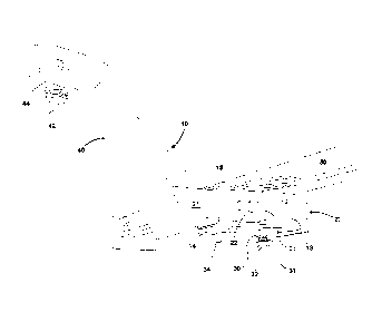
A receiver hitch includes a receiver with a rearward opening for receiving a forward end of a mount shank. The receiver has a side hole for receiving a hitch pin and a bottom hole for receiving a clamping bolt. The bottom hole is disposed forward of the side hole. When the mount shank is disposed in the receiver tube with the hitch pin inserted, tightening the clamping bolt urges a portion of the mount shank forward of the hitch pin upward into engagement with an upper interior surface of the receiver tube and also urges a portion of the mount shank rearward of the hitch pin into engagement with a lower interior surface of the receiver tube. In this configuration, movement of the mount shank within the receiver tube is reduced.


French Abstract

Un attelage récepteur comprend un récepteur avec une ouverture arrière pour recevoir une extrémité avant dune tige de montage. Le récepteur présente un côté latéral pour recevoir une cheville dattelage et un trou de fond pour recevoir un boulon de serrage. Le trou de fond est disposé à lavant du trou latéral. Lorsque la tige de montage est disposée dans le tube récepteur avec la cheville dattelage insérée, le serrage du boulon de serrage pousse une partie de la tige de montage à lavant de la cheville dattelage vers le haut pour assurer une mise en prise avec une surface intérieure supérieure du tube récepteur. Le serrage du boulon de serrage pousse également une partie de la tige de montage à larrière de la cheville dattelage pour assurer une mise en prise avec une surface intérieure inférieure du tube récepteur. Dans cette configuration, le mouvement de la tige de montage dans le tube récepteur est réduit.

Claims

Note: Claims are shown in the official language in which they were submitted.


THE EMBODIMENTS OF THE INVENTION FOR WHICH AN EXCLUSIVE
PROPERTY OR PRIVILEGE IS CLAIMED ARE DEFINED AS FOLLOWS:
1. A receiver hitch comprising:
a receiver tube having a forward end, a rearward end, a top wall, a bottom
wall and two
opposing receiver tube side walls, wherein the receiver rearward end includes
an opening sized
for receiving a forward end of a mount shank and wherein the mount shank has a
side hole sized
for receiving a hitch pin;
a receiver side hole disposed in each of the receiver tube side walls and
sized for
receiving the hitch pin;
a receiver bottom hole disposed in the bottom wall of the receiver tube and
sized for
receiving a threaded clamping bolt, wherein the receiver bottom hole is
disposed forward of the
receiver side hole; and
a threaded nut fixed to the receiver tube in alignment with the receiver
bottom hole and
sized for receiving a mating threaded portion of the clamping bolt;
wherein when the mount shank is disposed in the receiver tube with the hitch
pin inserted
through the receiver side hole and the mount shank side hole, a portion of the
mount shank
forward of the hitch pin is urged into engagement with an upper interior
surface of the receiver
tube by advancing the clamping bolt in the threaded nut;
whereby movement of the mount shank within the receiver tube is reduced.
2. The receiver hitch of claim 1 wherein the threaded nut comprises a
locking nut.
3. The receiver hitch of claim 1 wherein the clamping bolt comprises a head
configured for
providing theft deterrence.
4. The receiver hitch of claim 1 wherein a portion of the mount shank
rearward of the hitch
pin is urged into engagement with a lower interior surface of the receiver
tube by tightening the
clamping bolt.
5. A receiver hitch comprising:
6

a receiver tube comprising:
a rearward opening for receiving a mount shank having a mount shank side hole
sized for receiving a hitch pin;
a receiver side hole sized for receiving the hitch pin; and
a bottom hole disposed forward of the receiver side hole and sized for
receiving
an upwardly projecting clamping member; and
means for adjustably advancing the clamping member upward into contact with
the mount shank when it is disposed in the receiver tube and the hitch pin is
inserted
through the receiver side hole and the mount shank side hole;
wherein when the clamping member is advanced upward into contact with the
mount
shank, a portion of the mount shank forward of the receiver side hole is urged
upward into
engagement with an upper interior surface of the receiver tube;
whereby movement of the mount shank within the receiver tube is restricted.
6. The receiver hitch of claim 5 wherein when the clamping member is
advanced upward
into contact with the mount shank, a portion of the mount shank rearward of
the receiver side
hole is urged downward into engagement with a lower interior surface of the
receiver tube.
7. The hitch of claim 5 wherein the means for adjustably advancing the
clamping member
upward comprises a threaded bolt.
8. The hitch of claim 5 wherein the means for adjustably advancing the
clamping member
upward comprises a threaded nut fixedly mounted to the bottom wall of the
receiver tube.
9. The hitch of claim 8 wherein the threaded nut comprises a lock nut.
10. The hitch of claim 5 wherein the means for adjustably advancing the
clamping member
upward comprises a threaded portion formed in the receiver bottom hole and
sized for receiving
a mating portion of the threaded bolt.
7

11. The receiver hitch of claim 5 wherein the clamping member comprises a
head configured
for providing theft deterrence.
12. A receiver hitch comprising in combination:
a receiver tube having a side hole sized for receiving a hitch pin and a
threaded bottom
hole disposed forward of the receiver side hole;
a mount shank positioned within the receiver tube and having a rearward shank
portion
disposed rearward of the receiver side hole, a mount shank side hole aligned
with the receiver
side hole, and a forward shank portion disposed forward of the receiver side
hole and over the
threaded bottom hole;
said hitch pin being inserted through the aligned receiver side hole and
through the mount
shank side hole; and
a clamping bolt sized for mating with the threaded bottom hole;
wherein when the clamping bolt is rotated, it urges the forward shank portion
upward
against an upper interior surface of the receiver tube;
whereby movement of the mount shank within the receiver tube is reduced.
13. The receiver hitch of claim 12 wherein when the clamp bolt is rotated,
it urges the
rearward shank portion downward against a lower interior surface of the
receiver tube.
14. The receiver hitch of claim 12, wherein the threaded bottom hole is
formed, at least in
part, by a threaded locking nut fixedly mounted to the bottom of the receiver
tube.
15. The receiver hitch of claim 12 wherein the clamping bolt comprises a
head configured for
providing theft deterrence.
8

Description

Note: Descriptions are shown in the official language in which they were submitted.


CA 2961226 2017-03-20
HITCH NOISE PREVENTION DEVICE
BACKGROUND
[0001] This invention relates generally to receiver hitch assemblies
for coupling a
towing vehicle to a trailer or other object to be towed. More specifically,
the invention relates to
a device that reduces the movement - and the resulting rattling noise ¨ that
occurs between a
receiver and ball mount of such a hitch assembly during towing.
[0002] Typically, the receiver of a hitch assembly will include a
receiver tube,
and the ball mount will include a mount shank. In order for the mount shank to
be easily inserted
into the receiver tube, the receiver tube will be slightly larger than the
mount shank. Due to this
slight difference in size, the mount shank will have a tendency to move within
the receiver tube
and thereby produce a rattling noise. While the movement and resultant noise
may not have a
detrimental effect on the receiver hitch assembly, the rattling noise tends to
be an annoyance.
[0003] Prior art devices and systems intended to address this noise
issue suffer
from a number of disadvantages. Among others, they have numerous components
and as a result
are complex to install and have correspondingly high manufacturing and
maintenance costs.
Therefore, there is a continuing need for an improved apparatus for preventing
rattling in a
receiver hitch assembly. It is an object of the present invention to provide
such an apparatus.
[0004] Additional objects and advantages of the invention will be
set forth in the
description that follows, and in part will be apparent from the description,
or may be learned by
practice of the invention. The objects and advantages of the invention may be
realized and
obtained by means of the instrumentalities and combinations pointed out in
this specification and
the appended claims.
SUMMARY
[0005] To achieve the foregoing objects, and in accordance with the
purposes of
the invention as embodied and broadly described in this document, there is
provided a receiver
hitch that includes a receiver tube having a forward end, a rearward end, a
top wall, a bottom
wall and two opposing side walls. The receiver rearward end includes an
opening sized for
receiving a forward end of a mount shank that has a side hole sized for
receiving a hitch pin. A
receiver side hole is disposed in the receiver tube side wall and also is
sized for receiving the
hitch pin. A receiver bottom hole is disposed in the bottom wall forward of
the receiver side
1

CA 2961226 2017-03-20
hole and is sized for receiving an upwardly projecting clamping member. The
receiver tube also
includes means for adjustably advancing the clamping member upward and
retracting it
downward. When the mount shank is disposed in the receiver tube with the hitch
pin inserted,
advancing the clamping member will urge a forward portion of the mount shank
upward into
engagement with an upper interior surface of the receiver tube and also will
urge a rearward
portion of the mount shank into engagement with a lower interior surface of
the receiver tube. In
this engaged position, movement of the mount shank within the receiver tube is
reduced.
[0006] In some advantageous embodiments, the clamping member
comprises a
clamping bolt; and the means for adjustably advancing and retracting the
clamping member
comprises a threaded nut fixed to the bottom of the receiver tube and sized
for receiving a mating
threaded portion of the clamping bolt. The threaded nut can comprise a locking
nut. In some
embodiments, the means for advancing and retracting the clamping member
comprises a
threaded portion formed in the receiver bottom hole and sized for receiving a
mating threaded
portion of the clamping bolt. The clamping bolt can have a head configured for
providing theft
deterrence.
BRIEF DESCRIPTION OF THE DRAWINGS
[0007] The accompanying drawings, which are incorporated in and
constitute a
part of the specification, illustrate the presently preferred embodiments of
the invention and,
together with the general description given above and the detailed description
of the preferred
embodiments given below, serve to explain the principles of the invention.
[0008] FIG. 1 is a bottom side perspective view of one embodiment of
a receiver
hitch assembly according to the present invention showing a ball mount
inserted into a receiver
mounted to a vehicle for towing.
[0009] FIG. 2 is larger view of a portion of the receiver hitch
assembly of FIG. 1,
showing the mount shank and receiver tube.
[0010] FIG. 3 is a side elevation partial cross-sectional view a
portion of the
receiver hitch assembly of FIG. 1 showing the clamping bolt pressing the mount
shank into
engagement with the upper and lower interior surfaces of the receiver tube.
[0011] FIGs. 4 is a rear elevational view of the receiver tube of
FIG. 1 showing
the clamping bolt inserted into the receiver bottom hole.
2

CA 2961226 2017-03-20
[0012] FIGs. 5 a rear elevation partial cross-sectional view of the
receiver tube of
FIG. 4, taken through line A-A shown in FIG. 3.
DESCRIPTION
[0013] Reference will now be made in more detail to presently
preferred
embodiments of the invention. While the invention is described more fully with
reference to
these examples, the invention in its broader aspects is not limited to the
specific details,
representative devices, and illustrative examples shown and described. Rather,
the description
which follows is to be understood as a broad, teaching disclosure directed to
persons of ordinary
skill in the appropriate arts, and not as limiting upon the invention.
[0014] It will be appreciated that terms such as "forward,"
"rearward," "upper,"
"inner," "outer," "vertical," "horizontal," "bottom," "below," "top," "side,"
"inwardly,"
"outwardly," "downwardly" and "lower" and other positionally descriptive terms
used in this
specification are used merely for ease of description and refer to the
orientation of the referenced
components as shown in the figures. It should be understood that any
orientation of the
components described herein is within the scope of the present invention.
[0015] FIGs. 1-5 illustrate one embodiment of a receiver hitch
assembly
according to the present invention, generally designated as 10. The receiver
hitch assembly 10
includes a ball mount 40 and a receiver 20 mounted to a vehicle 50. The
receiver 20 includes a
receiver tube 12 that has a forward end 13 and free rearward end 14 with an
opening 18 for
receiving a shank 21 of the ball mount 40. The ball mount 40 includes a hitch
ball (not shown)
with a threaded shank 42 that is removably mounted to the ball mount 40 with a
hitch ball nut 44.
The receiver tube 12 terminates at forward plate 60 that has holes 37, which
allow air into the
receiver tube 12 and allow fluids to drain from it. The receiver tube 12 also
has a top wall 62, a
bottom wall 64 and two opposing side walls 66, each of which has a side hole
22 for receiving a
lateral hitch pin 26. The mount shank 21 also has side holes 23 for receiving
the hitch pin 26.
When the mount shank 21 is inserted into the receiver tube 12 so that the
receiver side holes 22
align with the mount shank side holes 23, the hitch pin 26 can be inserted
through the side holes
22, 23 to prevent the mount shank 21 from moving longitudinally within the
receiver tube 12.
The hitch pin 26 can be held in place by a hitch pin clip 34, as is known in
the art, to prevent
lateral forces from removing the hitch pin 26 from the side holes 22, 23.
3

CA 2961226 2017-03-20
[0016] Still referring to FIGs. 1-5, the receiver tube bottom wall
64 has an
unthreaded pass-through bottom hole 24 positioned forward of the side holes
22. A locking nut
30 is fixedly mounted to the receiver tube 12 over the bottom hole 24, such as
by welding, so
that the threaded hole of the locking nut 30 aligns with the bottom hole 24.
The locking nut 30
receives a clamping member in the form of a clamping screw or bolt 32 having a
threaded shank
31. When the mount shank 21 is disposed in the receiver tube 12 with the hitch
pin 26 inserted,
the clamping bolt 32 can be tightened to advance it upward into contact with
the mount shank 21
and thereby urge the mount shank forward end 52 upward into engagement with
the upper
interior surface 28 of the receiver tube 12. At the same time, the mount shank
rearward end 54 is
urged into engagement with the lower interior surface 29 of the receiver tube
12. The locking
nut 30 prevents the clamping bolt 32 from backing out during towing. In this
configuration,
movement of the mount shank 21 within the receiver tube 12 is restricted
during towing, thereby
reducing the rattling noise associated with such movement.
[0017] Positioning the bottom hole 24 and clamping bolt 32 forward
of the hitch
pin 26 provides a number of advantages over prior art receiver hitch
assemblies. When the
clamping bolt 32 is tightened, it provides excellent frictional engagement
between the mount
shank 21 and the interior of the receiver tube 12 with only one clamping bolt.
At the same time
that the clamping bolt 32 presses the mount shank forward end 52 upward into
frictional
engagement with the receiver tube upper interior surface 28, it also exerts a
downward force on
the mount shank rearward end 54 to urge it into frictional engagement with the
receiver tube
lower interior surface 29 by utilizing the hitch pin 26 as a fulcrum. Also
because of this
configuration, the clamping bolt 32 exerts a load on the mount shank 21 that
acts in the same
direction as the load exerted by a trailer coupled to the ball mount 40 for
towing (i.e., a
downward load on the mount shank rearward end 54). Because this trailer load
acts in the same
direction as the clamping bolt load - rather than opposing the clamping bolt
load - the assembly
requires only one clamping bolt to achieve frictional engagement suitable to
restrict
movement and eliminate rattling between the mount shank and the receiver tube
during towing.
[0018] A user of the receiver hitch assembly 10 can simply and
conveniently
remove the ball mount shank 21 from the receiver tube 12 by loosening the
clamping bolt 32. In
some embodiments, the clamping bolt 32 can have a configuration selected to
provide theft
deterrence, such as a security screw or bolt that requires a special tool to
be driven or removed
4

CA 2961226 2017-03-20
from the threaded hole of the locking nut 30. Such a configuration can
include, for example, a
screw or bolt that utilizes a head design similar to those used for locking
lug nuts or another
tamper-proof head design, such a Torx head, Torx tamper proof head, locking
head, alien
head, spanner head, or the like.
[0019] From the foregoing, it can be seen that the apparatus of the
present
invention possesses numerous advantages. It provides an assembly of relative
simple and
economical construction that is cost-effective to manufacture and maintain,
and yet it still can
effectively eliminate rattling during towing. The location of the clamp bolt
greatly simplifies the
assembly as compared to other designs that use two or more set screws.
[0020] Upon reading this disclosure, additional advantages and
modifications will
readily occur to those skilled in the art. Therefore, the invention in its
broader aspects is not
limited to the specific details, representative devices, and illustrative
examples shown and
described. Accordingly, departures may be made from such details without
departing from the
spirit or scope of the general inventive concept.

Representative Drawing
A single figure which represents the drawing illustrating the invention.
Administrative Status

2024-08-01:As part of the Next Generation Patents (NGP) transition, the Canadian Patents Database (CPD) now contains a more detailed Event History, which replicates the Event Log of our new back-office solution.

Please note that "Inactive:" events refers to events no longer in use in our new back-office solution.

For a clearer understanding of the status of the application/patent presented on this page, the site Disclaimer , as well as the definitions for Patent , Event History , Maintenance Fee  and Payment History  should be consulted.

Event History

Description Date
Common Representative Appointed 2019-10-30
Grant by Issuance 2019-03-12
Inactive: Cover page published 2019-03-11
Inactive: Final fee received 2019-01-29
Pre-grant 2019-01-29
Letter Sent 2018-12-27
Notice of Allowance is Issued 2018-12-27
Inactive: QS passed 2018-12-18
Inactive: Approved for allowance (AFA) 2018-12-18
Amendment Received - Voluntary Amendment 2018-12-06
Inactive: S.30(2) Rules - Examiner requisition 2018-11-26
Inactive: Report - No QC 2018-11-23
Letter Sent 2018-11-02
Request for Examination Requirements Determined Compliant 2018-10-30
Request for Examination Received 2018-10-30
Advanced Examination Requested - PPH 2018-10-30
Advanced Examination Determined Compliant - PPH 2018-10-30
Amendment Received - Voluntary Amendment 2018-10-30
All Requirements for Examination Determined Compliant 2018-10-30
Application Published (Open to Public Inspection) 2018-09-14
Inactive: Cover page published 2018-09-13
Letter Sent 2017-04-24
Inactive: Reply to s.37 Rules - Non-PCT 2017-04-11
Inactive: Single transfer 2017-04-11
Inactive: Filing certificate - No RFE (bilingual) 2017-03-30
Inactive: First IPC assigned 2017-03-29
Inactive: IPC assigned 2017-03-29
Inactive: Request under s.37 Rules - Non-PCT 2017-03-27
Application Received - Regular National 2017-03-23

Abandonment History

There is no abandonment history.

Maintenance Fee

The last payment was received on 2019-03-07

Note : If the full payment has not been received on or before the date indicated, a further fee may be required which may be one of the following

  • the reinstatement fee;
  • the late payment fee; or
  • additional fee to reverse deemed expiry.

Patent fees are adjusted on the 1st of January every year. The amounts above are the current amounts if received by December 31 of the current year.
Please refer to the CIPO Patent Fees web page to see all current fee amounts.

Fee History

Fee Type Anniversary Year Due Date Paid Date
Application fee - standard 2017-03-20
Registration of a document 2017-04-11
Request for examination - standard 2018-10-30
Final fee - standard 2019-01-29
MF (application, 2nd anniv.) - standard 02 2019-03-20 2019-03-07
MF (patent, 3rd anniv.) - standard 2020-03-20 2020-03-13
MF (patent, 4th anniv.) - standard 2021-03-22 2021-03-12
MF (patent, 5th anniv.) - standard 2022-03-21 2022-03-11
MF (patent, 6th anniv.) - standard 2023-03-20 2023-03-10
MF (patent, 7th anniv.) - standard 2024-03-20 2024-03-15
Owners on Record

Note: Records showing the ownership history in alphabetical order.

Current Owners on Record
U-HAUL INTERNATIONAL, INC.
Past Owners on Record
DAN HAMBY
MARCO GARCIA
Past Owners that do not appear in the "Owners on Record" listing will appear in other documentation within the application.
Documents

To view selected files, please enter reCAPTCHA code :


To view images, click a link in the Document Description column. To download the documents, select one or more checkboxes in the first column and then click the "Download Selected in PDF format (Zip Archive)" or the "Download Selected as Single PDF" button.

List of published and non-published patent-specific documents on the CPD .

If you have any difficulty accessing content, you can call the Client Service Centre at 1-866-997-1936 or send them an e-mail at CIPO Client Service Centre.


Document
Description 
Date
(yyyy-mm-dd) 
Number of pages   Size of Image (KB) 
Description 2017-03-19 5 248
Abstract 2017-03-19 1 17
Claims 2017-03-19 3 106
Drawings 2017-03-19 4 106
Representative drawing 2018-08-07 1 13
Claims 2018-10-29 3 105
Claims 2018-12-05 3 107
Maintenance fee payment 2024-03-14 47 1,943
Filing Certificate 2017-03-29 1 216
Courtesy - Certificate of registration (related document(s)) 2017-04-23 1 103
Acknowledgement of Request for Examination 2018-11-01 1 174
Reminder of maintenance fee due 2018-11-20 1 111
Commissioner's Notice - Application Found Allowable 2018-12-26 1 163
PPH supporting documents 2018-10-29 8 389
PPH request 2018-10-29 9 332
Examiner Requisition 2018-11-25 3 204
Amendment / response to report 2018-12-05 7 270
Request Under Section 37 2017-03-26 1 47
Response to section 37 2017-04-10 5 116
Final fee 2019-01-28 2 61