Note: Descriptions are shown in the official language in which they were submitted.
CA 02961512 2017-03-15
WO 2016/044625
PCT/US2015/050749
POLYMER IMPREGNATED BACKING MATERIAL, ABRASIVE ARTICLES
INCORPORATING SAME, AND PROCESSES OF MAKING AND USING
TECHNICAL FIELD
The present invention relates generally to polymer impregnated backing
materials,
abrasive articles including the same, and methods of making and using the
polymer
impregnated backing materials and abrasive articles.
BACKGROUND ART
Vulcanized fiber, sometimes also referred to as "vulcanized fibre" or "fish
paper", has
long been in use in the abrasive arts and refers to a leather-like or horn-
like material generally
formed from cellulose by compressing layers of chemically treated (for
example, with
metallic chlorides) cellulose derived from paper, paper pulp, rayon, or cloth.
Vulcanized
fiber is hydrophilic in nature and prone to absorbing moisture.
Abrasive articles that employ vulcanized fiber as a substrate material suffer
from a
well-recognized problem of a lack of dimensional stability (commonly called
shape distortion,
with specific examples of shape distortion being "curling" and "cupping")
caused by changes
in environmental moisture content (e.g., humidity). The lack of dimensional
stability can
detrimentally impact abrasive performance and cause premature end of life of
an abrasive
product (e.g., delamination, excessive warping of the abrasive article).
Various approaches
have been attempted to solve the problems related to the use of vulcanized
fiber substrates
but all suffer from certain drawbacks. Therefore, there continues to be a
demand for
improved abrasive articles.
BRIEF DESCRIPTION OF THE DRAWINGS
The present disclosure can be better understood, and its numerous features and
advantages made apparent to those skilled in the art by referencing the
accompanying
drawings.
FIG. 1 is an illustration of cross sectional view of an embodiment of a
composite
backing material.
FIG. 2 is an illustration of a cross-sectional view of an embodiment of a
coated
abrasive that includes a composite backing material.
FIG. 3 is an illustration of a flowchart of an embodiment of a method of
making
composite backing material.
Page 1 of 51
CA 02961512 2017-03-15
WO 2016/044625
PCT/US2015/050749
FIG. 4 is flowchart of an embodiment of a method of making an abrasive article
that
includes a composite backing material.
FIG. 5 is a photograph of a top view of a nonwoven stitch bonded fabric
suitable for
use in an embodiment.
FIG. 6 is a graph comparing the tensile strength in the machine direction of
an
embodiment of a composite backing material sample with a conventional
vulcanized fiber
backing material.
FIG. 7 is a graph comparing the tensile strength in the cross direction of an
embodiment of a composite backing material sample with a conventional
vulcanized fiber
backing material.
FIG. 8 is a graph comparing flexural modulus data in the machine direction of
an
embodiment of a composite backing material sample with a conventional
vulcanized fiber
backing material.
FIG. 9 is a graph comparing the flexural modulus data in the cross direction
of an
embodiment of a composite backing material sample with a conventional
vulcanized fiber
backing material.
FIG. 10 is a photograph of a conventional coated abrasive disc having a
vulcanized
fiber substrate showing the disc at its end of life with dulled abrasive
grains and clogged with
swarf.
FIG. 11 is a photograph of an inventive coated abrasive disc embodiment that
includes a composite backing showing that after grinding for the same amount
of time as the
conventional sample shown in FIG 10, there is less accumulated swarf and there
are still
exposed abrasive grains for continued grinding.
FIG. 12 is a bar graph comparing the amount of cumulative material removed by
conventional vulcanized fiber discs and inventive abrasive discs from Teakwood
and
Rosewood workpieces.
FIG. 13 is a graph showing the load-deformation response of a conventional
vulcanized fiber abrasive disc at room temperature, 100 C, and 130 C.
FIG. 14 is a graph showing the load-deformation response of an inventive
abrasive
disc at room temperature, 100 C, and 130 C.
FIG. 15 is a graph comparing the load-deformation response of an inventive
abrasive
disc with a conventional vulcanized fiber disc at 130 C.
Page 2 of 51
CA 02961512 2017-03-15
WO 2016/044625
PCT/US2015/050749
FIG. 16 is a graph comparing the flexural modulus of an inventive abrasive
disc with
a conventional vulcanized fiber disc at room temperature, 100 C, and 130 C.
FIG. 17A is a photograph of a conventional vulcanized fiber abrasive disc
prior to
dimensional stability testing at a temperature of 50 C and 25% relative
humidity.
FIG. 17B is a photograph of a conventional vulcanized fiber abrasive disc
after
dimensional stability testing at a temperature of 50 C and 25% relative
humidity.
FIG. 17C is a photograph of an inventive abrasive disc embodiment prior to
dimensional stability testing at a temperature of 50 C and 25% relative
humidity.
FIG. 17D is a photograph of an inventive abrasive disc embodiment after
dimensional
stability testing at a temperature of 50 C and 25% relative humidity.
FIG. 17E is a photograph of another inventive abrasive disc embodiment prior
to
dimensional stability testing at a temperature of 50 C and 25% relative
humidity.
FIG. 17F is a photograph of another inventive abrasive disc embodiment after
dimensional stability testing at a temperature of 50 C and 25% relative
humidity.
FIG. 18 is a bar graph comparing the percent (%) weight gained by the
conventional
abrasive disc and the inventive abrasive disc embodiments shown in FIGs 17A-F
due to
dimensional stability testing at a temperature of 50 C and 25% relative
humidity.
FIG. 19 is a graph showing the percent (%) change in dimensions of the
conventional
abrasive disc and the inventive abrasive disc embodiments shown in FIGs 17A-F
due to
dimensional stability testing at a temperature of 50 C and 25% relative
humidity.
FIG. 20A is a photograph of a conventional vulcanized fiber abrasive disc
prior to
dimensional stability testing at a temperature of 35 C and 85% relative
humidity.
FIG. 20B is a photograph of a conventional vulcanized fiber abrasive disc
after
dimensional stability testing at a temperature of 35 C and 85% relative
humidity.
FIG. 20C is a photograph of an inventive abrasive disc embodiment prior to
dimensional stability testing at a temperature of 35 C and 85% relative
humidity.
FIG. 20D is a photograph of an inventive abrasive disc embodiment after
dimensional
stability testing at a temperature of 35 C and 85% relative humidity.
FIG. 20E is a photograph of another inventive abrasive disc embodiment prior
to
dimensional stability testing at a temperature of 35 C and 85% relative
humidity.
FIG. 20F is a photograph of another inventive abrasive disc embodiment after
dimensional stability testing at a temperature of 35 C and 85% relative
humidity.
Page 3 of 51
CA 02961512 2017-03-15
WO 2016/044625
PCT/US2015/050749
FIG. 21 is a bar graph comparing the percent (%) weight gained by the
conventional
abrasive disc and the inventive abrasive disc embodiments shown in FIGs 20A-F
due to
dimensional stability testing at a temperature of 35 C and 85% relative
humidity.
FIG. 22 is a graph showing the percent (%) change in dimensions of the
conventional
abrasive disc and the inventive abrasive disc embodiments shown in FIGs 20A-F
due to
dimensional stability testing at a temperature of 35 C and 85% relative
humidity.
The use of the same reference symbols in different drawings indicates similar
or
identical items.
DETAILED DESCRIPTION OF EMBODIMENTS
The following description, in combination with the figures, is provided to
assist in
understanding the teachings disclosed herein. The following discussion will
focus on specific
implementations and embodiments of the teachings. This focus is provided to
assist in
describing the teachings and should not be interpreted as a limitation on the
scope or
applicability of the teachings.
The term "averaged," when referring to a value, is intended to mean an
average, a
geometric mean, or a median value. As used herein, the terms "comprises,"
"comprising,"
"includes," "including," "has," "having," or any other variation thereof, are
intended to cover
a non-exclusive inclusion. For example, a process, method, article, or
apparatus that
comprises a list of features is not necessarily limited only to those features
but can include
other features not expressly listed or inherent to such process, method,
article, or apparatus.
As used herein, the phrase "consists essentially of" or "consisting
essentially of" means that
the subject that the phrase describes does not include any other components
that substantially
affect the property of the subject.
Further, unless expressly stated to the contrary, "or" refers to an inclusive-
or and not
to an exclusive-or. For example, a condition A or B is satisfied by any one of
the following:
A is true (or present) and B is false (or not present), A is false (or not
present) and B is true
(or present), and both A and B are true (or present).
The use of "a" or "an" is employed to describe elements and components
described
herein. This is done merely for convenience and to give a general sense of the
scope of the
invention. This description should be read to include one or at least one and
the singular also
includes the plural, or vice versa, unless it is clear that it is meant
otherwise.
Page 4 of 51
CA 02961512 2017-03-15
WO 2016/044625
PCT/US2015/050749
Further, references to values stated in ranges include each and every value
within that
range. When the terms "about" or "approximately" precede a numerical value,
such as when
describing a numerical range, it is intended that the exact numerical value is
also included.
For example, a numerical range beginning at "about 25" is intended to also
include a range
that begins at exactly 25. Moreover, it will be appreciated that references to
values stated as
"at least about," "greater than," "less than," or "not greater than" can
include a range of any
minimum or maximum value noted therein.
As used herein, the phrase "average particle diameter" can be reference to an
average,
mean, or median particle diameter, also commonly referred to in the art as
D50.
Unless otherwise defined, all technical and scientific terms used herein have
the same
meaning as commonly understood by one of ordinary skill in the art to which
this invention
belongs. The materials, methods, and examples are illustrative only and not
intended to be
limiting. To the extent not described herein, many details regarding specific
materials and
processing acts are conventional and can be found in textbooks and other
sources within the
coated abrasive arts.
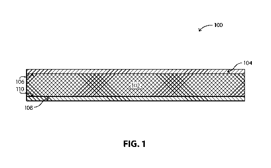
FIG. 1 shows an illustration of a cross section of a composite backing
material 100
embodiment. A composite backing material is comprised of a nonwoven fabric 102
impregnated with a first polymer composition and having a front fill layer 104
that is
disposed on a first side 106 of the polymer impregnated nonwoven fabric and a
back fill layer
108 that is disposed on a second side 110 of the polymer impregnated nonwoven
fabric.
FIG. 2 shows an illustration of a cross section of a coated abrasive article
200
embodiment. A composite backing material 202 is comprised of a polymer
impregnated
nonwoven fabric 204 having a front fill layer 206 that is disposed on a first
side 208 of the
polymer impregnated nonwoven fabric and a back fill layer 210 that is disposed
on a second
side 212 of the polymer impregnated nonwoven fabric. An abrasive layer 214 is
disposed on
the front fill layer 206. The abrasive layer 214 comprises abrasive particles
218 disposed on
or dispersed in a binder composition 220 (e.g., a make coat or an abrasive
slurry). An
optional size coat 222 is disposed on the abrasive layer. An optional
supersize coat 224 is
disposed on the size coat.
FIG. 3 is an illustration of a flowchart of an embodiment of a method 300 of
making
composite backing material according to an embodiment. Step 302 includes
mixing of
ingredients to form a first polymeric composition (also referred to herein as
a dip fill
Page 5 of 51
CA 02961512 2017-03-15
WO 2016/044625
PCT/US2015/050749
composition). In an embodiment, the ingredients comprise a mixture of a
combination of
phenolic resins and water. Step 304 includes impregnating (also called herein
"saturating") a
nonwoven fabric with the first polymeric composition to form a polymer
impregnated
nonwoven fabric. In an embodiment, the nonwoven fabric is a stitch bonded
fabric.
Optionally, Step 306 includes adjusting the amount of first polymeric
composition in the
nonwoven fabric (i.e., also referred to herein as adjusting the saturation, or
as adjusting the
amount of wet add-on weight). Step 308 includes curing, at least partially to
fully, the
polymer impregnated nonwoven fabric (i.e., curing at least partially to fully
the first
polymeric composition that permeates the nonwoven fabric). Step 310 includes
disposing a
front fill layer onto a first side of the polymer impregnated nonwoven fabric.
In an
embodiment, the front fill layer comprises a second polymer composition (also
called herein
a front fill composition). Step 312 includes curing, at least partially to
fully, the front fill
layer. Optionally, step 314 includes calendaring the front fill layer. Step
316 includes
disposing a back fill layer onto a second side of the polymer impregnated
nonwoven fabric.
In an embodiment, the back fill layer can comprise a third polymer formulation
(also called
herein a back fill composition). During step 318 includes curing, at least
partially to fully, of
the backfill layer to form the composite backing material. Optionally, step
320 includes
calendaring the back fill layer.
FIG. 4 is an illustration of a flowchart of an embodiment of a method 400 of
making a
composite backing material according to an embodiment. Step 402 includes
preparing a
composite backing material according to the steps of the method described
above in FIG. 3.
Step 404 includes disposing an abrasive layer on the front fill layer of the
composite backing
material to form an abrasive article. Step 406 includes curing, at least
partially to fully, of the
abrasive layer. Optionally, step 408 includes disposing a size coat on the
abrasive layer.
Optionally, step 410 includes disposing a super-size coat on the size coat.
FIG. 5 is an illustration of an example of a nonwoven stitch bonded fabric
comprised
of a plurality of batts (also called "webs" herein) joined together by a
thread that is stitched
through the plurality of batts. In an embodiment, the stich bonded fabric
comprises three
batts.
Composite Backing Material
A composite backing material can comprise a polymer impregnated nonwoven
fabric
having a front fill composition disposed on a first side of the polymer
impregnated nonwoven
Page 6 of 51
CA 02961512 2017-03-15
WO 2016/044625
PCT/US2015/050749
fabric and a back fill composition disposed on a second side of the polymer
impregnated
nonwoven fabric. The composite backing material possesses beneficial physical
properties
that contribute to unexpected beneficial and superior abrasive performance of
abrasive
articles that include the composite backing material.
Polymer Impregnated Nonwoven Fabric
The polymer impregnated nonwoven fabric comprises a nonwoven fabric
impregnated (i.e., saturated with) with a first polymeric composition (also
called herein a "dip
fill" composition or a "saturating" composition or a "saturant" composition).
The nonwoven fabric can be an organic material, an inorganic material, a
natural
material, a synthetic material, or a combination thereof. The nonwoven fabric
can be flexible,
rigid, or a combination thereof. The nonwoven fabric can comprise a single
type of fiber or a
plurality of different types of fibers. The nonwoven fabric can comprise
polyester, cotton,
nylon, silk, cellulose, cotton, viscose, jute, polyamide, polyamine, aramide,
poly-cotton,
rayon, or combinations thereof. Specific synthetics can comprise Kevlar,
Nomex, and
combinations thereof. The fabric can comprise virgin fibers or recycled
fibers. The
nonwoven fabric can be a finished fabric, or an unfinished fabric (i.e. "grey
fabric"), or a
combination thereof. In a particular embodiment, the nonwoven fabric is a
polyester fabric.
The nonwoven fabric can be a spun lace fabric, a chemically bonded fabric, a
thermally bonded fabric, a needle punched fabric, a stitch-bonded fabric, or
combinations
thereof. A stitch bonded fabric can be a maliwatt fabric, a malivies fabric, a
malimo fabric, a
malipol fabric, a voltex fabric, a kunit fabric, a multiknit fabric, or
combinations thereof, and
the like. In an embodiment, the nonwoven fabric is a stitch bonded fabric.
The stitch bonded fabric can comprise a single web (also called a batt) or a
plurality
of webs (batts). In an embodiment, the number of webs of the stitch bonded
fabric can be not
less than 1 web, such as not less than 2 webs, not less than 3 webs, or not
less than 4 webs.
In another embodiment, the number of webs of the stitch bonded fabric can be
not greater
than 10 webs, such as not greater than 9 webs, not greater than 8 webs, not
greater than 7
webs, or not greater than 6 webs. The number of webs of the stitch bonded
fabric can be
within a range comprising any pair of the previous upper and lower limits. In
a particular
embodiment, the number of webs of the stich bonded fabric is in the range of 1
to 10 webs,
such as 2 to 8 webs, or 3 to 7 webs. In a particular embodiment, the stitch
bonded material
comprises 3 webs.
Page 7 of 51
CA 02961512 2017-03-15
WO 2016/044625
PCT/US2015/050749
The stitch bonded fabric can have a particular type of stitch bond. The stitch
bonded
fabric can be a warp stitch bonded fabric, a weft stitch bonded fabric, or a
combination
thereof. In an embodiment, the stitch bonded fabric is warp stich bonded
fabric. The stich
bonded fabric can include any known stitch or combination of stitches in the
stitch bonded
fabric art. In a particular embodiment, the stitch bonded fabric includes a
chain stitch.
The nonwoven fabric and have a particular mass per unit area, such as g/m2
(GSM),
commonly called the "weight" of the fabric. In an embodiment, the weight of
the nonwoven
fabric can be not less than 50 GSM, not less than 100 GSM, not less than 200
GSM, not less
than 300 GSM, or not less than 350 GSM. In another embodiment, the weight of
the
nonwoven fabric can be not greater than 600 GSM, not greater than 500 GSM, not
greater
than 450 GSM, not greater than 400 GSM, or not greater than 390 GSM. The
amount of
weight of the nonwoven fabric can be within a range comprising any pair of the
previous
upper and lower limits. In a particular embodiment, the amount of weight of
the nonwoven
fabric can be in the range of not less than 50 GSM to not greater than 600
GSM, such as not
less than 100 GSM to not greater than 500 GSM, not less than 200 GSM to not
greater than
400 GSM, such as not less than 300 GSM to not greater than 390 GSM.
The nonwoven fabric can have a particular tensile strength in the Machine
Direction
(M/D). In an embodiment, the tensile strength of the nonwoven fabric in the
M/D can be not
less than 1 kgf/25mm, not less than 5 kgf/25mm, not less than 10 kgf/25mm, or
not less than
15 kgf/25mm. In another embodiment, the tensile strength of the nonwoven
fabric in the
M/D can be not greater than 100 kgf/25mm, not greater than 60 kgf/25mm, not
greater than
50 kgf/25mm, or not greater than 40 kgf/25mm. The tensile strength of the
nonwoven fabric
can be within a range comprising any pair of the previous upper and lower
limits. In a
particular embodiment, the tensile strength of the nonwoven fabric in the M/D
can be in a
range of not less than 1 kgf/25mm to not greater than 100 kgf/25mm, such as 5
kgf/25mm to
60 kgf/25mm, such as 10 kgf/25mm to 50 kgf/25mm, or 15kgf/25mm to 40 kgf/25mm.
The nonwoven fabric can have a particular tensile strength in the Cross
Direction
(C/D). In an embodiment, the tensile strength of the nonwoven fabric in the
C/D can be not
less than 1 kgf/25mm, not less than 5 kgf/25mm, not less than 10 kgf/25mm, or
not less than
15 kgf/25mm. In another embodiment, the tensile strength of the nonwoven
fabric in the C/D
can be not greater than 100 kgf/25mm, not greater than 60 kgf/25mm, not
greater than 50
kgf/25mm, or not greater than 40 kgf/25mm. The tensile strength of the
nonwoven fabric can
Page 8 of 51
CA 02961512 2017-03-15
WO 2016/044625
PCT/US2015/050749
be within a range comprising any pair of the previous upper and lower limits.
In a particular
embodiment, the tensile strength of the nonwoven fabric in the C/D can be in a
range of not
less than 1 kgf/25mm to not greater than 100 kgf/25mm, such as 5 kgf/25mm to
60
kgf/25mm, such as 10 kgf/25mm to 50 kgf/25mm, or 15kgf/25mm to 40 kgf/25mm.
The nonwoven fabric can have a particular tensile strength in the M/D and in
the C/D
such that the tensile strength in the M/D and tensile strength in the C/D have
a particular
relationship to each other. In an embodiment, the tensile strength in the M/D
is greater than
the tensile strength in the C/D. In another embodiment, the tensile in the M/D
is less than the
tensile strength in the C/D. In another embodiment, the tensile strength in
the M/D is
approximately the same as the tensile strength in the C/D. In an embodiment,
the tensile
strength in in the M/D and in the C/D can both be greater than a particular
minimum value.
In an embodiment, the tensile strength of the nonwoven fabric in both the M/D
and in the
C/D can be not less than 1 kgf/25mm, not less than 5 kgf/25mm, not less than
10 kgf/25mm,
or not less than 15 kgf/25mm. In another embodiment, the tensile strength of
the nonwoven
fabric in both the M/D and in the C/D can be not greater than 100 kgf/25mm,
not greater than
60 kgf/25mm, not greater than 50 kgf/25mm, or not greater than 40 kgf/25mm.
The tensile
strength of the nonwoven fabric in both the M/D and in the C/D can be within a
range
comprising any pair of the previous upper and lower limits. In a particular
embodiment, the
tensile strength of the nonwoven fabric in both the M/D and in the C/D can be
in a range of
not less than 1 kgf/25mm to not greater than 100 kgf/25mm, such as 5 kgf/25mm
to 60
kgf/25mm, such as 10 kgf/25mm to 50 kgf/25mm, or 15kgf/25mm to 40 kgf/25mm.
The nonwoven fabric can have a particular elastic modulus, also known as
"Young's
modulus" or "tensile modulus". In an embodiment, the elastic modulus of the
nonwoven
fabric can be not less than 0.01 GPa, not less than 0.025 GPa, not less than
0.05 GPa, or not
less than 0.1 GPa. In another embodiment, the elastic modulus of the nonwoven
fabric can
be not greater than 1 GPa, not greater than 0.8 GPa, not greater than 0.6 GPa,
not greater than
0.5 GPa, or not greater than 0.4 GPa. The elastic modulus of the nonwoven
fabric can be
within a range comprising any pair of the previous upper and lower limits. In
a particular
embodiment, the elastic modulus of the nonwoven fabric can be in a range of
not less than
0.01 GPa to not greater than 1 GPa, such as 0.1 GPa to 0.4 GPa.
The nonwoven fabric can have a particular elongation at break. In an
embodiment,
the elongation at break of the nonwoven fabric can be not less than 5 mm, not
less than 10
Page 9 of 51
CA 02961512 2017-03-15
WO 2016/044625
PCT/US2015/050749
mm, not less than 20 mm, or not less than 25 mm. In another embodiment, the
elongation at
break of the nonwoven fabric can be not greater than 70 mm, not greater than
60 mm, not
greater than 50 mm, or not greater than 45 mm. The elongation at break of the
nonwoven
fabric can be within a range comprising any pair of the previous upper and
lower limits. In a
particular embodiment, the elongation at break of the nonwoven fabric can be
in a range of
not less than 5 mm to not greater than 70 mm, such as 20 mm to 50 mm.
The nonwoven fabric can have a particular thickness. In an embodiment, the
thickness of the nonwoven fabric can be not less than 0.2 mm, such as not less
than 0.4 mm,
not less than 0.5 mm, not less than 0.6 mm, not less than 0.7 mm, not less
than 0.8 mm, or not
less than 0.9 mm. In another embodiment, the thickness of the nonwoven fabric
can be not
greater than 4 mm, such as not greater than 3 mm, not greater than 2 mm, not
greater than 1.8
mm, not greater than 1.6 mm, not greater than 1.4 mm, or not greater than 1.2
mm. The
thickness of the nonwoven fabric can be within a range comprising any pair of
the previous
upper and lower limits. In a particular embodiment, the thickness of the
nonwoven fabric can
be in a range of not less than 0.2 mm to not greater than 4 mm, such as 0.5 mm
to 0.8 mm or
0.8 mm to 1.4 mm.
The nonwoven fabric can comprise any combination of the above features. In a
specific embodiment, the nonwoven fabric comprises a warp stitch bonded
polyester fabric
having three webs and a weight in a range of 360 to 400 g/m2.
First Polymeric Composition
As stated above, the nonwoven fabric is impregnated with a first polymeric
composition. The polymer impregnated nonwoven fabric can be described in terms
of the
first polymeric composition when cured, partially cured, or fully cured.
A first polymeric composition can be formed of a single polymer or a blend of
polymers. The first polymeric composition can comprise a phenolic polymer, a
resorcinol
polymer, a melamine polymer, a urea polymer, or combinations thereof. The
phenolic
polymer, melamine polymer, or urea polymer can comprise a single prepolymer
resin or a
blend of resins. Phenolic polymers can comprise phenol formaldehyde resole
resins. Resole
resins are generally made using alkali hydroxides with a formaldehyde to
phenol ratio of
about 1.0 to 3.0 at a pH of 7 to13. In an embodiment the first polymeric
composition
comprises a phenolic resole resin. In another embodiment, the first polymeric
composition
comprises a mixture of a plurality of phenolic resole resins. In an
embodiment, the first
Page 10 of 51
CA 02961512 2017-03-15
WO 2016/044625
PCT/US2015/050749
polymeric composition can comprise from two to five phenolic resole resins. In
a specific
embodiment, the first polymeric composition comprises a mixture of a first
phenolic resole
resin and a second phenolic resole resin.
Resole resins can be classified by a number of features, such as the
formaldehyde to
phenol ratio (F/P ratio) prior to reaction, free formaldehyde content (FFC) of
the polymer
after reaction, free phenol content (FPC) after reaction, gel time at a
specific temperature, and
the water tolerance of the resin. In an embodiment, the F/P ratio can be in a
range of 0.95 to
2.5, such as 0.95 to 1.1, or 1.2 to 1.5, or 1.6 to 1.8, or 1.9 to 2.2, or a
combination thereof. In
an embodiment, the FFC can be in a range of 0.02% to 3.3% by weight of the
resin, such as
about 0.02% to 0.09%, or 0.2% to 0.45%, or 0.5% to 0.8%, or 1.0% to 1.3%, or
2.5% to 3%,
or combinations thereof. In an embodiment, the FPC can be in a range of 2% to
5%, or 4% to
7%, or 12% to 15%, or 16% to 20%, or combinations thereof. In an embodiment,
the gel
time at 121 C can be in range of 5 minutes to 30 minutes, such as 7-11
minutes, 8-12 minutes,
9-10 minutes, 10-12 minutes, 18-22 minutes, 19-26 minutes, or combinations
thereof. In an
embodiment, the water tolerance is in a range of 100% to 600%, such as 100 to
300%, 100 to
350%, 150 to 300%, 150 to 350%, 400 to 480%, 400 to 550%, 430 to 500%, or
combinations
thereof. In an embodiment, the first polymeric composition comprises a
phenolic resole resin,
also referred to herein as a high temperature (HT) phenolic resin having an
F/P ratio in a
range of 1.2 to 1.5, a gel time at 121 C in a range of 18-22 minutes; and a
water tolerance in a
range of 400 to 480%. In another embodiment, the first polymeric composition
comprises a
phenolic resole resin, also referred to herein as a low temperature (LT)
phenolic resin, having
an F/P ratio in a range of 1.6 to 1.8, a gel time at 121 C in a range of 10-12
minutes; and a
water tolerance in a range of 430 to 500%. In another embodiment the first
polymeric
composition comprises a phenolic resole resin, also referred to herein as
"CGF2" phenolic
resin, having an F/P ratio in a range of 1.9 to 2.2, a gel time at 121 C in a
range of 7-11
minutes; and a water tolerance in a range of 150 to 300%.
In an embodiment, the uncured first polymeric composition can comprise:
70 wt% to 100 wt% of total phenolic resin; and 0 wt% to 30 wt% water, wherein
the
percentages are based on a total weight of the first polymeric composition and
all the
percentages of the ingredients add up to 100 wt%. Optionally, from about 0.1
wt% to about 5
wt% of additives can also be included in the first polymeric composition. If
one or more
additives are included, the amount of the other ingredients can be adjusted so
that the total
Page 11 of 51
CA 02961512 2017-03-15
WO 2016/044625
PCT/US2015/050749
amounts of the ingredients in the first polymeric composition adds up to 100
wt%. The total
phenolic resin can comprise a single phenolic resin, or a plurality of
phenolic resins, such as
from two to five phenolic resins.
In another embodiment, the uncured first polymeric composition can comprise:
35 wt% to 55 wt% of a first phenolic resin;
35 wt% to 55 wt% of a second phenolic resin; and
0 wt% to 30 wt% water, wherein the percentages are based on a total weight of
the
first polymeric composition and all the percentages of the ingredients add up
to 100 wt%.
Optionally, from about 0.1 wt% to about 5 wt% of additives can also be
included in the first
polymeric composition. If one or more additives are included, the amount of
the other
ingredients can be adjusted so that the total amounts of the ingredients in
the first polymeric
composition adds up to 100 wt%. In a particular embodiment, the first phenolic
resin is a
high temperature (HT) phenolic resin having an F/P ratio in a range of 1.2 to
1.5, a gel time at
121 C in a range of 18-22 minutes; and a water tolerance in a range of 400 to
480%. In a
particular embodiment, the second phenolic resin is a low temperature (LT)
phenolic resin,
having an F/P ratio in a range of 1.6 to 1.8, a gel time at 121 C in a range
of 10-12 minutes;
and a water tolerance in a range of 430 to 500%.
In another embodiment, the uncured first polymeric composition can comprise:
40 wt% to 50 wt% of a first phenolic resin;
40 wt% to 50 wt% of a second phenolic resin and
0 wt% to 20 wt% water, wherein the percentages are based on a total weight of
the
first polymeric composition and all the percentages of the ingredients add up
to 100 wt%. In
a particular embodiment, the first phenolic resin is a high temperature (HT)
phenolic resin
having an F/P ratio in a range of 1.2 to 1.5, a gel time at 121 C in a range
of 18-22 minutes;
and a water tolerance in a range of 400 to 480%. In a particular embodiment,
the second
phenolic resin is a low temperature (LT) phenolic resin, having an F/P ratio
in a range of 1.6
to 1.8, a gel time at 121 C in a range of 10-12 minutes; and a water tolerance
in a range of
430 to 500%.
Alternatively, the polymer impregnated fabric can be described with respect to
a
cured composition. In an embodiment, a cured first polymeric composition can
comprise:
95 wt% to 100 wt% of total phenolic resin, wherein the percentages are based
on a total
weight of the first polymeric composition and all the percentages of the
ingredients add up to
Page 12 of 51
CA 02961512 2017-03-15
WO 2016/044625
PCT/US2015/050749
100 wt%. Optionally, from about 0.1 wt% to about 5 wt% of additives can also
be included
in the first polymeric composition. If one or more additives are included, the
amount of the
other ingredients can be adjusted so that the total amounts of the ingredients
in the first
polymeric composition adds up to 100 wt%. The total phenolic resin can
comprise a single
phenolic resin, or a plurality of phenolic resins, such as from two to five
phenolic resins.
In another embodiment, the cured first polymeric composition can comprise:
40 wt% to 60 wt% of a first phenolic resin; and
40 wt% to 60 wt% of a second phenolic resin, wherein the percentages are based
on a
total weight of the first polymeric composition and all the percentages of the
ingredients add
up to 100 wt%. Optionally, from about 0.1 wt% to about 5 wt% of additives can
also be
added to the first polymeric composition. If one or more additives are
included, the amount
of the other ingredients can be adjusted so that the total amounts of the
ingredients in the first
polymeric composition adds up to 100 wt%. In a particular embodiment, the
first phenolic
resin is a high temperature (HT) phenolic resin having an F/P ratio in a range
of 1.2 to 1.5, a
gel time at 121 C in a range of 18-22 minutes; and a water tolerance in a
range of 400 to
480%. In a particular embodiment, the second phenolic resin is a low
temperature (LT)
phenolic resin, having an F/P ratio in a range of 1.6 to 1.8, a gel time at
121 C in a range of
10-12 minutes; and a water tolerance in a range of 430 to 500%.
Alternatively, the first polymeric composition can be expressed as a ratio of
the first
phenolic resole resin and the second phenolic resole resin. In an embodiment,
the first
phenolic resole resin and the second phenolic resole resin are present in a
ratio (first
resin:second resin) ranging from 1:9 to 9:1, such as from 1:2 to 2:1; from
1:1.5 to 1.5:1;.from
1:1.25 to 1.25:1; or about 1:1.
It will be appreciated that the first polymeric composition can be distributed
uniformly or non-uniformly throughout the nonwoven fabric. In an embodiment,
the first
polymeric composition is uniformly dispersed throughout the nonwoven fabric.
Amount of Impregnation (Saturation) ¨ Add-on Weight
The amount of first polymeric composition that impregnates (i.e., saturates)
the
nonwoven fabric (i.e., the amount of first polymeric composition that adheres
to and/or is
absorbed by the nonwoven fabric) is also known as the "add-on" weight of the
first polymeric
composition. The amount of saturation can be expressed as "wet" add-on weight,
which is
the weight of the uncured first polymeric composition and can include water.
Alternatively,
Page 13 of 51
CA 02961512 2017-03-15
WO 2016/044625
PCT/US2015/050749
the amount of saturation can be expressed a "dry" add-on weight, which is the
weight of the
cured first polymeric composition and does not include water. The amount of
add-on weight,
whether wet add-on weight or dry add-on weight, can be expressed as a
percentage of the
original weight of the backing material. For example, if the nonwoven fabric
weighs: 100
g/m2 prior to impregnation; 150 g/m2 after impregnation (uncured); and 125
g/m2after
curing, then the impregnated nonwoven fabric would be considered 50 wt%
saturated "wet"
and 25 wt% saturated "dry". Alternatively, the amount of impregnation can be
expressed as
the mass of the add-on weight of the first polymeric composition. For example,
if the
nonwoven fabric weighs: 100 g/m2 prior to saturation; weighs 150 g/m2 after
saturation
(uncured), and 125 g/m2 after curing, then the amount of saturation would be
expressed as 50
g/m2 of wet add-on weight and 25 g/m2 of dry add-on weight of first polymeric
composition.
The dry add-on weight of the first polymeric composition to the nonwoven
fabric can
be in a particular range. In an embodiment, the dry add-on weight of the first
polymeric
composition can be not less than 200 g/m2 (GSM), such as not less than 225
GSM, not less
than 250 GSM, not less than 275 GSM, not less than 300 GSM, not less than 325
GSM, not
less than 350 GSM, not less than 375 GSM, not less than 400 GSM, or not less
than 425
GSM. In another embodiment, the dry add-on weight of the nonwoven fabric can
be not
greater than 650 GSM, such as not greater than 625 GSM, not greater than 600
GSM, not
greater than 575 GSM, not greater than 550 GSM, not greater than 525 GSM, not
greater than
500 GSM, or not greater than 475 GSM. The dry add-on weight of the nonwoven
fabric can
be within a range comprising any pair of the previous upper and lower limits.
In a particular
embodiment, the dry add-on weight of the nonwoven fabric can be in a range of
not less than
200 GSM to not greater than 650 GSM, such as 300 GSM to 550 GSM, such as 400
GSM to
500 GSM, or 425 GSM to 475 GSM.
The dry add-on weight of the first polymeric composition can be a percentage
of the
weight of the unsaturated nonwoven fabric. In an embodiment, the dry add-on
weight of the
first polymeric composition can be not less than 50 wt%, such as not less than
about 55 wt%,
not less than about 60 wt%, not less than about 65 wt%, not less than about 70
wt%, not less
than about 75 wt%, not less than about 80 wt%, not less than about 85 wt%, not
less than
about 90 wt%, or not less than about 95 wt%. In another embodiment, the dry
add-on weight
of the nonwoven fabric can be not greater than 200 wt%, such as not greater
than 190 wt%,
not greater than 180 wt%, not greater than 170 wt%, not greater than 160 wt%,
not greater
Page 14 of 51
CA 02961512 2017-03-15
WO 2016/044625
PCT/US2015/050749
than 150 wt%, not greater than 140 wt%, not greater than 135 wt%, not greater
than 130 wt%,
not greater than 125 wt%, or not greater than 120 wt%. The dry add-on weight
of the first
polymeric composition can be within a range comprising any pair of the
previous upper and
lower limits. In a particular embodiment, the dry add-on weight of the first
polymeric
composition can be in a range of not less than 50 wt% to not greater than 200
wt%, such as
75 wt% to 175 wt%, such as 100 wt% to 150 wt%, or 110 wt% to 140 wt%.
Alternatively, the polymer impregnated nonwoven fabric can be described by the
ratio
of the weight of the nonwoven fabric (Weight,,,) to the dry add-on weight of
the first
polymeric composition (Weightd,p). In an embodiment, the ratio of Weightõ,:
Weightd,p can
be in a range from 1.0:0.5 to 1.0:5.0, such as from 1.0:0.75 to 1.0:2.5, from
1.0:1.0 to 1.0:1.5.
In a particular embodiment, the ratio of Weightõ,: Weightd,p is in a range
from 1.0:1.1 to
1.0:1.25.
Front Fill Layer
As stated above, the composite backing material comprises a polymer
impregnated
nonwoven fabric having a front fill layer disposed on a first side of the
polymer impregnated
nonwoven fabric. The front fill layer comprises a second polymeric composition
(also called
herein the "front fill composition"). The second polymeric composition can be
described in
terms of being cured, partially cured, or fully cured.
The second polymeric composition can be the same as or different from the
first
polymeric composition as described above. The second polymeric composition can
comprise
a single phenolic resole resin or a mixture of a plurality of phenolic resole
resins as described
above. In an embodiment, the second polymeric composition comprises a mixture
of a first
phenolic resole resin and a second phenolic resole resin. The first phenolic
resole resin and a
second phenolic resole resin can be the same as or different from the first
phenolic resole
resin and a second phenolic resole resin that comprise the first polymeric
composition as
described above. In an embodiment, the first phenolic resole resin of the
second polymeric
composition is the same as the first phenolic resole resin present in the
first polymeric
composition. In another embodiment, the second phenolic resole resin of the
second
polymeric composition is the same as the second phenolic resole resin present
in the first
polymeric composition. In another embodiment, the first and second phenolic
resole resins
are the same as the first and second phenolic resole resins of the first
polymeric composition.
Page 15 of 51
CA 02961512 2017-03-15
WO 2016/044625
PCT/US2015/050749
The first phenolic resole resin and second phenolic resole resin can be in a
particular
ratio to each other. In an embodiment, the ratio of first phenolic resole
resin to second
phenolic resole resin (first resin:second resin) is in a range of about 1:9 to
9:1, such as about
1:4 to 4:1, such as about 1:3 to 3:1, or about 1:2 to 2:1. In an embodiment,
the first and
second phenolic resole resins are present in a different ratio to each other
than in the first
polymeric composition.
The second polymeric composition can further comprise, if desired, a filler
material in
an amount of 0 wt% to 50 wt% of the weight of the second polymeric
composition. In an
embodiment, the second polymeric composition comprises a filler in an amount
from 1 wt%
to 50 wt%, such as about 10 wt% to 45 wt%, about 15 wt% to 40 wt%, or about 20
wt% to
35wt%. In an embodiment, the filler can comprise calcium carbonate,
wollastonite, clay, or a
combination thereof.
In an embodiment, the uncured front fill composition can comprise:
wt% to 26 wt% of a first phenolic resole resin;
15 35 wt% to 52 wt% of a second phenolic resole resin;
wt% to 40 wt% of a filler; and
0 wt% to 5 wt% water, wherein the percentages are based on a total weight of
the
front fill composition and all the percentages of the ingredients add up to
100 wt%.
Optionally, from about 0.1 wt% to about 5 wt% of additives can also be added
to the front fill
20 composition. If one or more additives are included, the amount of the
other ingredients can
be adjusted so that the total amounts of the ingredients in the front fill
composition add up to
100 wt%.
In an embodiment, the cured second polymeric composition can comprise:
17 wt% to 28 wt% of a first phenolic resole resin;
25 35 wt% to 54 wt% of a second phenolic resole resin; and
27 wt% to 40 wt% of a filler; wherein the percentages are based on a total
weight of
the front fill composition and all the percentages of the ingredients add up
to 100 wt%.
Optionally, from about 0.1 wt% to about 5 wt% of additives can also be added
to the front fill
composition. If one or more additives are included, the amount of the other
ingredients can
be adjusted so that the total amounts of the ingredients in the front fill
composition adds up to
100 wt%.
Page 16 of 51
CA 02961512 2017-03-15
WO 2016/044625
PCT/US2015/050749
The dry add-on weight of the second polymeric composition refers to the amount
of
cured second polymeric composition disposed on the first side of the polymer
impregnated
nonwoven fabric. The dry add-on weight of the second polymeric composition to
the
nonwoven fabric can be in a particular range. In an embodiment, the dry add-on
weight of
the second polymeric composition can be not less than 5 g/m2 (GSM), such as
not less than
GSM, not less than 15 GSM, not less than 20 GSM, not less than 25 GSM, not
less than
30 GSM, not less than 35 GSM, not less than 40 GSM, or not less than 50 GSM.
In another
embodiment, the dry add-on weight of the second polymeric composition can be
not greater
than 200 GSM, such as not greater than 175 GSM, not greater than 150 GSM, not
greater
10 than 125 GSM, not greater than 100 GSM, not greater than 90 GSM, not
greater than 80
GSM, or not greater than 70 GSM. The dry add-on weight of the second polymeric
composition can be within a range comprising any pair of the previous upper
and lower limits.
In a particular embodiment, the dry add-on weight of the second polymeric
composition can
be in a range of not less than 5 GSM to not greater than 200 GSM, such as 20
GSM to 175
GSM, such as 30 GSM to 125 GSM, or 40 GSM to 100 GSM.
Backfill Layer
As stated above, the composite backing material comprises a polymer
impregnated
nonwoven fabric having a back fill layer disposed on a second side of the
polymer
impregnated nonwoven fabric. The back fill layer comprises a third polymeric
composition
(also called herein the back fill composition). The third polymeric
composition can be the
same as or different from the first polymeric composition or the second
polymeric
compositions as described above. The third polymeric composition can comprise
an acrylic
latex resin. The third polymeric composition can further comprise a phenolic
resole resin.
The phenolic resole resin can be single phenolic resole resin, or a mixture of
a plurality of
phenolic resole resins. The phenolic resole resin can be the same as or
different from the first
and second phenolic resole resins described above with respect to the first
polymeric
composition and the second polymeric composition. The third polymeric
composition can
further comprise a filler. The filler can be the same as or different from the
filler of the
second polymeric composition.
In an embodiment, the uncured third polymeric composition can comprise:
wt% to 55 wt% of an acrylic latex;
10 wt% to 20 wt% of a phenolic resole resin;
Page 17 of 51
CA 02961512 2017-03-15
WO 2016/044625
PCT/US2015/050749
20 wt% to 30 wt% of a filler; and
0 wt% to 20 wt% water, wherein the percentages are based on a total weight of
the
third polymeric composition and all the percentages of the ingredients add up
to 100 wt%.
Optionally, from about 0.1 wt% to about 5 wt% of additives can also be added
to the third
polymeric composition. If one or more additives are included, the amount of
the other
ingredients can be adjusted so that the total amounts of the ingredients in
the third polymeric
composition add up to 100 wt%.
In an embodiment, the cured third polymeric composition can comprise:
40 wt% to 62 wt% of an acrylic latex;
12 wt% to 20 wt% of a phenolic resole resin; and
25 wt% to 40 wt% of a filler, wherein the percentages are based on a total
weight of
the third polymeric composition and all the percentages of the ingredients add
up to 100 wt%.
Optionally, from about 0.1 wt% to about 5 wt% of additives can also be added
to the third
polymeric composition. If one or more additives are included, the amount of
the other
ingredients can be adjusted so that the total amounts of the ingredients in
the third polymeric
composition add up to 100 wt%.
In an embodiment, the phenolic resole resin of the third polymeric composition
is a
third phenolic resole resin that is different than the phenolic resole resins
of the first
polymeric composition or the second polymeric composition. In an embodiment,
the third
phenolic resole resin can comprise a phenolic resin having an F/P ratio in a
range of 1.9 to 2.2,
a gel time at 121 C in a range of 7-11 minutes; and a water tolerance in a
range of 150 to
300%.
The dry add-on weight of the third polymeric composition refers to the amount
of
cured third polymeric composition disposed on the second side of the polymer
impregnated
nonwoven fabric. The dry add-on weight of the third polymeric composition can
be in a
particular range. In an embodiment, the dry add-on weight of the third
polymeric
composition can be not less than 5 g/m2 (GSM), such as not less than 10 GSM,
not less than
15 GSM, not less than 20 GSM, not less than 25 GSM, not less than 30 GSM, not
less than
GSM, not less than 40 GSM, not less than 50 GSM, or not less than 60 GSM. In
another
30 embodiment, the dry add-on weight of the third polymeric composition can
be not greater
than 200 GSM, such as not greater than 180 GSM, not greater than 170 GSM, not
greater
than 160 GSM, not greater than 150 GSM, not greater than 140 GSM, not greater
than 130
Page 18 of 51
CA 02961512 2017-03-15
WO 2016/044625
PCT/US2015/050749
GSM, not greater than 120 GSM, not greater than 110 GSM, or not greater than
100 GSM.
The dry add-on weight of the third polymeric composition can be within a range
comprising
any pair of the previous upper and lower limits. In a particular embodiment,
the dry add-on
weight of the third polymeric composition can be in a range of not less than 5
GSM to not
greater than 200 GSM, such as 30 GSM to 150 GSM, such as 40 GSM to 120 GSM, or
60
GSM to 100 GSM.
Composite Backing Material
The composite backing material can be described on a percent weight basis of
the
nonwoven backing material, the cured first polymeric composition, the cured
front fill
composition, and the cured third polymeric composition. In an embodiment, a
completed
composite backing material can comprise:
35wt% to 45 wt% nonwoven fabric;
40wt% to 50 wt% cured first polymeric composition;
2 wt% to 10 wt% cured second composition (front fill); and
3 wt% to 15 wt% cured third polymeric composition (back fill), wherein the
percentages are based on the total weight of the composite backing material
and all the
percentages of the components add up to 100 wt%.
Beneficial Properties of a Composite Backing Material
The fully cured composite backing material possesses physical properties that
are
surprisingly beneficial and that contribute to superior abrasive performance
of an abrasive
article that includes the composite backing material.
Tensile strength in the machine direction (M/D) can be measured using an
Instron
5982 with a 2 kN load cell. The composite backing material samples had a total
sample
length of 200 mm, a sample width of 25 mm, a gauge length of 127 mm, and were
tested at a
deformation rate of 300 mm/min. In an embodiment, the composite backing
material can
have a tensile strength in the machine direction (M/D) in a range 60 Kg/25 mm
to 160 Kg/25
mm, such as 65 Kg/25 mm to 150 Kg/25 mm, 70 Kg/25 mm to 140 Kg/25 mm, 75 Kg/25
mm
to 130 Kg/25 mm, 80 Kg/25 mm to 120 Kg/25 mm, or 85 Kg/25 mm to 115 Kg/25 mm.
The
tensile strength in the machine direction can be within a range comprising any
pair of the
previous upper and lower limits.
Tensile strength in the cross-direction (C/D) can be measured using an Instron
5982
with a 2 kN load cell. The composite backing material samples had a total
sample length of
Page 19 of 51
CA 02961512 2017-03-15
WO 2016/044625
PCT/US2015/050749
200 mm, a sample width of 25 mm, a gauge length of 127 mm, and were tested at
a
deformation rate of 300 mm/min. In an embodiment, the composite backing
material can
have a tensile strength in the cross direction (CID) in a range of 40Kg/25 mm
to 120 Kg/25
mm, such as 45 Kg/25 mm to 110 Kg/25 mm, 50 Kg/25 mm to 100 Kg/25 mm, or 55
Kg/25
mm to 95 Kg/25 mm. The tensile strength in the cross direction can be within a
range
comprising any pair of the previous upper and lower limits.
Flexural Modulus in the machine direction (MID) can be measured using an
Instron
5966 with a 10KN load cell. The composite backing material samples had a total
sample
length of 10 cm, a sample width of 1 inch mm, a gauge length of 127 mm, and
were tested at
a deformation rate of 1 mm/min (flexural grip used: three point bending), with
the test based
on ASTM D-790. In an embodiment, the flexural modulus in the machine direction
for the
composite backing material is in a range of about 0.8 GPa to 7 GPa, such as
0.9 GPa to 6 GPa,
1 GPa to 5 GPa, 1.1 GPa to 4 GPa, 1.2 GPa to 3.5 GPa, or 1.3 GPa to 3 GPa. The
flexural
modulus in the machine direction can be within a range comprising any pair of
the previous
upper and lower limits.
Flexural Modulus in the cross direction (CID) can be measured using an Instron
5966
with a 10KN load cell. The composite backing material samples had a total
sample length of
10 cm, a sample width of 1 inch mm, a gauge length of 127 mm, and were tested
at a
deformation rate of 1 mm/min (flexural grip used: three point bending), with
the test based on
ASTM D-790. In an embodiment, the flexural modulus in the cross direction for
the
composite backing material is in a range of about 0.2 GPa to 5 GPa, such as
0.3 GPa to 4 GPa,
0.4 GPa to 3 GPa, 0.5 GPa to 2.5 GPa, 0.6 GPa to 2 GPa, or 0.7 GPa to 1.5 GPa.
The
flexural modulus in the cross direction can be within a range comprising any
pair of the
previous upper and lower limits.
Load deformation response (i.e., a measure of the maximum load before failure)
of
the composite backing material can be measured at various temperatures, such
as elevated
temperatures generated during abrasive operation in comparison to room
temperature (about
25 C). Load deformation response is measured according to the same method
used to derive
the tensile strength properties of the composite backing, except that the
Instron testing
machine is equipped with an in situ furnace that heats the material samples at
a rate of 10
degrees C per minute up to the desired testing temperature (e.g., 100 C and
130 C).
Ideally, a load deformation response at an elevated temperature compared to
room
Page 20 of 51
CA 02961512 2017-03-15
WO 2016/044625
PCT/US2015/050749
temperature would comprise a percent decrease of zero (i.e., no loss of load
capacity at the
elevated temperature); however, actual deformation responses comprise a non-
zero percent
decrease. Surprisingly and beneficially, Applicants have discovered that the
present
embodiments comprise a percent decrease of less than 40% at elevated
temperatures
experienced during actual grinding.
In an embodiment, the load deformation response of a composite backing
material at
100 C compared to room temperature can comprise a percent decrease of less
than 40%,
such as less than 39%, less than 38%, less than 37%, less than 35%%, less than
30%, less
than 20%, less than 10%, less than 9%, less than 8%, less than 7%, less than
6%, less than
5%, less than 4%, less than 3%, less than 2%, or less than 1.5%. Still, the
load deformation
response at 100 C is measurable, such that in an embodiment, the load
deformation response
of a composite backing material at 100 C compared to room temperature is
greater than
0.1%, such as greater than 0.5 %, or greater than 1%. The load deformation
response of the
composite backing material at 100 C compared to room temperature can be in a
range a
range comprising any pair of the previous upper and lower limits. In a
particular embodiment,
the load deformation response of the composite backing material at 100 C
compared to room
temperature is a percent decrease in a range of 1.44% to 39%.
In another embodiment, the load deformation response of a composite backing
material at 130 C compared to room temperature was a percent decrease of less
than 60%,
such as less than 50%, less than 40, less than 30%, less than 20%, less than
19%, less than
18%, less than 17%, less than 16%, or even less than 15.5%. In an embodiment,
the load
deformation response of a composite backing material at 130 C compared to
room
temperature was a percent decrease of not less than 15.1%. Still, the load
deformation
response at 130 C is measurable, such that in an embodiment, the load
deformation response
of a composite backing material at 130 C compared to room temperature is
greater than 1%,
such as greater than 5 %, greater than 10%, or greater than 15%. The load
deformation
response of the composite backing material at 130 C compared to room
temperature can be
in a range a range comprising any pair of the previous upper and lower limits.
In a particular
embodiment, the load deformation response of the composite backing material at
130 C
compared to room temperature is a percent decrease in a range of 60% to 15.1%.
Applicants discovered that it is surprising and particularly beneficial that
the
deformation load response at elevated temperatures is such a small percent
decrease in
Page 21 of 51
CA 02961512 2017-03-15
WO 2016/044625
PCT/US2015/050749
comparison to conventional vulcanized fiber backing material. For example,
conventional
vulcanized fiber backings have a deformation response at 100 C compared to
room
temperature of at least a 40% decrease (compared to only a 1.44% decrease for
an inventive
sample), and a deformation response at 130 C compared to room temperature of
at least a
66% percent decrease (compared to only a 15.1 % decrease for an inventive
sample). (See
FIGs. 13-15). Applicants further point out that inventive samples at 130 C
surprisingly and
beneficially actually have a maximum load that exceeds the maximum load for
conventional
vulcanized fiber samples.
The composite backing material, and abrasive article embodiments that include
the
composite backing material, can have a particular moisture resistance and
dimensional
stability under certain temperature and relative humidity conditions.
Applicants have
discovered that the composite backing material embodiments, and abrasive
article
embodiments that include the composite backing material embodiments, have
surprisingly
beneficial moisture resistance and dimensional stability (i.e., weight
stability and resistance to
changes in dimension, such as resistance to warping, curling, and cupping) as
measured under
certain temperature and relative humidity conditions.
In an embodiment, abrasive articles placed in a climate chamber at a
temperature of
50 C and 25 % relative humidity (RH) for 2.5 hours, can have a % weight gain
of less than
5.5%, such as less than 5%, less than 4%, less than 3%, less than 2%, even
less than 1.5%.
Ideally, an abrasive article can have no weight gain (i.e., a gain of 0%),
however, typically an
abrasive disc will have some weight gain greater than zero percent, such as
greater than 0.1%,
greater than 0.2 %, greater than 0.3%, greater than 0.4%, greater than 0.5%,
greater than
0.6%, greater than 0.7%, greater than 0.8%, greater than 0.9%, or greater than
1.0%. The
weight gain of the abrasive article at 50 C and 25% RH can be in a range
comprising any
pair of the previous upper and lower limits. In a particular embodiment, the
weight gain of
the abrasive article at 50 C and 25% RH is in a range of 0.1% to 5%, such as
0.5% to 4.5%.
(See FIG. 18)
In another embodiment, abrasive articles placed in a climate chamber at a
temperature
of 35 C and 85 % relative humidity (RH) for 2.5 hours, can have a % weight
gain of less
than 2.25%, such as less than less than 2%, less than 1%, or even less than
0.5%. Ideally, an
abrasive article can have no weight gain (i.e., a gain of 0%), however,
typically an abrasive
disc will have some weight gain greater than zero percent, such as greater
than 0.1%, greater
Page 22 of 51
CA 02961512 2017-03-15
WO 2016/044625
PCT/US2015/050749
than 0.2 %, or greater than 0.3%. The weight gain of the abrasive article at
35 C and 85%
RH can be in a range comprising any pair of the previous upper and lower
limits. In a
particular embodiment, the weight gain of the abrasive article at 35 C and
85% RH is in a
range of 0.1% to 2.25%, such as 0.2% to 2%. (See FIG. 21)
In an embodiment, abrasive articles placed in a climate chamber at a
temperature of
50 C and 25 % relative humidity (RH) for 2.5 hours can have a "three-point
dimensional
stability" determined by selecting three points on the surface of the abrasive
disc: point 1 at
the left edge of the disc; point 2 at the edge of the center hole of the disc;
and point 3 at the
right edge of the disc (See FIG 17A-F) and recording their vertical distance
while the disc is
lying flat prior to being placed in the climate chamber and after being placed
in the climate
chamber for the specified period of time. The difference in vertical distance
for the selected
points can be used to calculate the change in dimension as a percent
difference for each point.
In an embodiment, the dimensional stability is a function of all three points.
In an
embodiment, an abrasive article can have a three-point dimensional stability
at 50 C and
25 % RH where all three points have a percent (%) change in dimension of less
than 700%,
such as less than 600%, less than 500%, less than 400%, less than 300%, less
than 200%, less
than 100%, less than 50%, even less than 25%. Ideally, an abrasive article can
have no
change in three-point dimensional stability (i.e., a percent change of 0%),
however, typically
an abrasive article will have a change of three-point dimensional stability at
50 C and 25 %
RH for all three points greater than zero percent for each point, such as
greater than 0.1%,
greater than 1 %, greater than 2%, greater than 3%, greater than 5%, greater
than 8%, greater
than 10%, greater than 12%, greater than 14%, or greater than 15%. The three-
point
dimensional stability at 50 C and 25 % RH for all three points can be in a
range comprising
any pair of the previous upper and lower limits. In a particular embodiment,
an abrasive
article can have a three-point dimensional stability at 50 C and 25% RH where
the %
difference in dimension for all three points is in a range of 0.1% to 700%,
such as 1% to
650%. (See FIG. 19)
In another embodiment, abrasive articles placed in a climate chamber at a
temperature
of 35 C and 85% relative humidity (RH) for 2.5 hours can have a "three-point
dimensional
stability" determined by selecting three points on the surface of the abrasive
disc: point 1 at
the left edge of the disc; point 2 at the edge of the center hole of the disc;
and point 3 at the
right edge of the disc (See FIG 20A-F) and recording their vertical distance
while the disc is
Page 23 of 51
CA 02961512 2017-03-15
WO 2016/044625
PCT/US2015/050749
laying flat prior to being placed in the climate chamber and after being
placed in the climate
chamber for the specified period of time. The difference in vertical distance
for the selected
points can be used to calculate the change in dimension as a percent
difference for each point.
In an embodiment, the dimensional stability is a function of all three points.
In an
embodiment, an abrasive article can have a three-point dimensional stability
at 35 C and
85% RH where all three points have a % change in dimension of less than 75%,
such as less
than 70%, less than 65%, less than 60%, less than 55%, less than 50%, less
than 45%, less
than 40%, less than 35%, less than 30%, or even less than 25%. Ideally, an
abrasive article
can have no change in three-point dimensional stability (i.e., a percent
change of 0%),
however, typically an abrasive article will have a change of three-point
dimensional stability
at 35 C and 85% RH for all three points greater than zero percent for each
point, such as
greater than 0.1%, greater than 1%, greater than 2%, greater than 3%, greater
than 5%,
greater than 8%, greater than 10%, greater than 12%, greater than 14%, or
greater than 15%.
The three-point dimensional stability at 35 C and 85% RH for all three points
can be in a
range comprising any pair of the previous upper and lower limits. In a
particular embodiment,
an abrasive article can have a three-point dimensional stability at 35 C and
85% RH where
the % difference in dimension for all three points is in a range of 0.1% to
75%, such as 1% to
70%. (See FIG. 22)
Method of Making a Composite Backing Material
Mixing a First Polymeric Composition
A first polymeric composition can comprise a polymeric composition as
described
above. The ingredients of the first polymeric composition are thoroughly mixed
together.
Mixing can be conducted using high shear conditions, moderate shear
conditions, low shear
conditions, or combinations thereof. Typically, mixing occurs until the
ingredients are
thoroughly mixed.
During mixing of the first polymeric composition, the ingredients can be added
to the
first polymeric composition one by one, in batches, or all at once. Typically
the ingredients
are added one by one to the first polymeric composition. If the ingredients
are added one by
one or in batches, the first polymeric composition can be agitated for a
period of time until
the ingredient has sufficiently mixed into the first polymeric composition.
Typical agitation
times range from about 1 minute to about 2 hours, depending on the ingredient
or ingredients
being added to the first polymeric composition.
Page 24 of 51
CA 02961512 2017-03-15
WO 2016/044625
PCT/US2015/050749
The temperature of the first polymeric composition can be adjusted if desired
during
mixing. The temperature of the first polymeric composition during mixing can
be in a range
of about 15 C to about 45 C, such as about 20 C to about 25 C. The pH of
the first
polymeric composition can be adjusted during mixing. The pH can be adjusted by
the
addition of an acid, a base, a buffer solution, or a combination thereof if
desired. The pH of
the first polymeric composition is typically basic, but can be close to
neutral, such as in a
range of about 7 pH to about 13 pH.
Water can be added to the first polymeric composition in an amount to adjust
or
control the viscosity of the first polymeric composition as desired. The
viscosity of the first
polymeric composition can be monitored as it is being prepared. In an
embodiment, the
viscosity of the first polymeric composition is adjusted to be within a
particular range. In an
embodiment, the viscosity of the first polymeric composition is in a range of
about 10 cps to
about 300 cps, such as about 50 cps to about 250 cps, or about 75 cps to about
200 cps based
on the addition of water to the first polymeric composition.
Saturating the Nonwoven Fabric
A suitable nonwoven fabric, such as described above, can be saturated (also
referred
to herein as being "impregnated") with first polymeric composition by any
suitable manner
that applies a sufficient amount of first polymeric composition so that the
nonwoven fabric
becomes thoroughly soaked with the first polymeric composition. In an
embodiment,
saturation can be accomplished by dipping, spraying, submerging, coating, or
washing the
nonwoven fabric with or in the first polymeric composition, or combinations
thereof. The
saturation can occur as a single step or multiple steps, such as multiple
dipping steps or
multiple spraying steps of the nonwoven fabric with the first polymeric
composition, or
combinations thereof. In a specific embodiment, the nonwoven fabric is dipped
into a first
polymeric composition. In another embodiment a nonwoven fabric is sprayed with
a first
polymeric composition.
Adjusting Saturation
Adjusting the saturation of the first polymeric composition can be
accomplished by
any method or mechanism that does not overly degrade the nonwoven fabric.
Suitable
methods and mechanisms of adjusting the first polymeric composition can re-
apply and/or
remove a desired amount of first polymeric composition so that the nonwoven
fabric has a
desired amount of saturation. Adjusting the amount of first polymeric
composition can be
Page 25 of 51
CA 02961512 2017-03-15
WO 2016/044625
PCT/US2015/050749
accomplished in a single step or multiple steps. Adjusting the amount of first
polymeric
composition can include pressing, squeezing, brushing, squeegeeing, blowing,
dabbing,
blotting, rollering, shaking, or combinations thereof, and the like. In a
specific embodiment,
the polymer impregnated nonwoven fabric can be squeezed, such as between a
pair of rollers
to adjust the saturation of the saturated backing material.
Curing
After saturation of the nonwoven fabric with first polymeric composition, and
any
optional adjustment of the amount of saturation of the backing material, the
saturated or
saturation adjusted pre-cure nonwoven fabric can undergo curing, partially to
fully, to form a
composite backing material (i.e., The polymer impregnated nonwoven fabric has
been
impregnated with cured polymeric saturation composition). Curing can be
conducted in a
single step or multiple steps. Curing can be accomplished by exposure to a
heat source, such
as a heating tunnel or oven, including a multi stage oven, or the like.
Alternative heating
sources can include exposure to infrared radiation lamps, or the like.
In an embodiment, the polymer impregnated nonwoven fabric is cured at a
particular
temperature or temperature range. The add-on amino or phenolic resin
saturating the
nonwoven fabric is cured. In an embodiment, the curing temperature is at least
about 95 C,
such as at least about 100 C, such as at least about 110 C, or at least
about 125 C. In an
embodiment, the curing temperature is not greater than about 175 C, such as
not greater than
about 170 C, not greater than about 165 C, not greater than about 160 C, not
greater than
about 155 C, or not greater than about 150 C. The curing temperature of the
nonwoven
fabric can be within a range comprising any pair of the previous upper and
lower limits. In a
particular embodiment, the curing temperature can be in the range of not less
than 100 C to
about 150 C.
In accordance with an embodiment, the polymer impregnated nonwoven fabric can
be
cured to a particular degree (i.e., the first polymeric composition saturating
the backing
material is cured to a particular degree). In an embodiment, the polymer
impregnated
nonwoven fabric can be partially cured or completely cured. In an embodiment,
the polymer
impregnated nonwoven fabric is partially cured. In an embodiment, the polymer
impregnated
nonwoven fabric is partially cured not greater than 95%, such as not greater
than 90%, not
greater than 80%, not greater than 70%, not greater than 60%, not greater than
55%, or not
greater than 50%. In an embodiment, the polymer impregnated nonwoven fabric is
partially
Page 26 of 51
CA 02961512 2017-03-15
WO 2016/044625
PCT/US2015/050749
cured not less than 5%, such as not less than 10%, not less than 20%, not less
than 30% or not
less than 35%. The amount of partially curing the polymer impregnated nonwoven
fabric can
be within a range comprising any pair of the previous upper and lower limits.
In a particular
embodiment, the polymer impregnated nonwoven fabric is partially cured not
greater than
95% and not less than 5%, such not greater than 60% and not less than 20%, or
not greater
than 50% and not less than 30%.
In another embodiment, the polymer impregnated nonwoven fabric can be cured to
a
degree that the surface of the partially cured nonwoven fabric is rendered
tack free (i.e., not
tacky, does not stick to fingers), but the partially cured fabric is still
pliable and suitable for
further processing.
Partially to fully curing the polymer impregnated nonwoven fabric forms a
completed
polymer impregnated nonwoven fabric.
Applying the Front Fill Layer
A second polymeric composition (front fill composition) as described above can
be
prepared by mixing together the required ingredients. The ingredients of the
second
polymeric composition are thoroughly mixed together. Mixing shear conditions,
addition of
ingredients, mixing temperature, and pH range of the composition are as
described above
with respect to the first polymeric composition.
Water can be added to the second polymeric composition in an amount to adjust
or
control the viscosity of the second polymeric composition as desired. The
viscosity of the
second polymeric composition can be monitored as it is being prepared. In an
embodiment,
the viscosity of the second polymeric composition is adjusted to be within a
particular range.
In an embodiment, the viscosity of the second polymeric composition is in a
range of about
900 cps to about 2000 cps, such as about 1000 cps to about 1900 cps, about
1100 cps to about
1800 cps, or about 1200 cps to about 1700 cps based on the addition of water
to the second
polymeric composition.
The front fill layer can be applied to a first side of the polymer impregnated
nonwoven fabric by any suitable coating method or coating apparatus. Suitable
coating
apparatus can include a drop die coater, a knife coater, a curtain coater, a
die coater, or a
vacuum die coater. Coating methodologies can include either contact or non-
contact coating
methods. Suitable coating methods can include two roll coating, three roll
reverse coating,
Page 27 of 51
CA 02961512 2017-03-15
WO 2016/044625
PCT/US2015/050749
knife over roll coating, slot die coating, gravure coating, rotary printing,
extrusion, spray
coating, or combinations thereof.
Curing the Front Fill Layer
The second polymeric composition can be cured partially to fully in the same
manner
as described above with respect the first polymer composition. In a particular
embodiment,
the second polymeric composition is partially cured to not greater than 60%
and not less than
20%. In a particular embodiment, the second polymeric composition curing
temperature is in
a range of not less than 100 C to about 150 C.
Calendaring the Front Fill Layer
The front fill layer can optionally be processed to smooth the surface of the
front fill
layer. The front fill layer can be smoothed by any known acceptable process.
In an
embodiment, calendaring of the front fill layer is performed.
Applying the Back Fill Layer
A third polymeric composition (back fill composition) as described above can
be
prepared by mixing together the required ingredients. The ingredients of the
third polymeric
composition are thoroughly mixed together. Mixing shear conditions, addition
of ingredients,
mixing temperature, and pH range of the composition are as described above
with respect to
the first polymeric composition.
Water can be added to the third polymeric composition in an amount to adjust
or
control the viscosity of the second polymeric composition as desired. The
viscosity of the
third polymeric composition can be monitored as it is being prepared. In an
embodiment, the
viscosity of the third polymeric composition is adjusted to be within a
particular range. In an
embodiment, the viscosity of the second polymeric composition is in a range of
about 900 cps
to about 2000 cps, such as about 1000 cps to about 1900 cps, about 1100 cps to
about 1800
cps, or about 1200 cps to about 1700 cps based on the addition of water to the
third polymeric
composition.
The back fill layer can be applied to a second side of the polymer impregnated
nonwoven fabric by any suitable coating method or coating apparatus. Suitable
coating
apparatus can include a drop die coater, a knife coater, a curtain coater, a
die coater, or a
vacuum die coater. Coating methodologies can include either contact or non-
contact coating
methods. Suitable coating methods can include two roll coating, three roll
reverse coating,
Page 28 of 51
CA 02961512 2017-03-15
WO 2016/044625
PCT/US2015/050749
knife over roll coating, slot die coating, gravure coating, rotary printing,
extrusion, spray
coating, or combinations thereof.
Curing the Back Fill Layer
The third polymeric composition can be cured partially to fully in the same
manner as
described above with respect the first polymer composition. In a particular
embodiment, the
third polymeric composition is partially cured to not greater than 60% and not
less than 20%.
In a particular embodiment, the third polymeric composition curing temperature
is in a range
of not less than 100 C to about 150 C. Upon completion of the curing of the
back fill layer
the composite backing material is complete. The composite backing material can
be stored or
subjected to additional processing such as is required to construct a coated
abrasive article.
Calendaring the Back Fill Layer
The back fill layer can optionally be processed to smooth the surface of the
back fill
layer. The back fill layer can be smoothed by any known acceptable process. In
an
embodiment, calendaring of the back fill layer is performed.
Preparation of a Coated Abrasive
The composite backing material can be used to make a coated abrasive article.
In an
embodiment, an abrasive layer is disposed on the composite backing material.
Optionally, a
size coat, a supersize coat, a back coat or any other number of compliant or
intermediary
layers known in the art of making a coated abrasive article can be applied to
the amino or
phenolic resin treated backing to construct a coated abrasive article.
Abrasive Layer
An abrasive layer can comprise a make coat or an abrasive slurry. The make
coat or
abrasive slurry can comprise a plurality of abrasive particles, also referred
to herein as
abrasive grains, retained by a polymer binder composition. The polymer binder
composition
can be an aqueous composition. The polymer binder composition can be a
thermosetting
composition, a radiation cured composition, or a combination thereof.
Abrasive Grains
Abrasive grains can include essentially single phase inorganic materials, such
as
alumina, silicon carbide, silica, ceria, and harder, high performance
superabrasive grains such
as cubic boron nitride and diamond. Additionally, the abrasive grains can
include composite
particulate materials. Such materials can include aggregates, which can be
formed through
slurry processing pathways that include removal of the liquid carrier through
volatilization or
Page 29 of 51
CA 02961512 2017-03-15
WO 2016/044625
PCT/US2015/050749
evaporation, leaving behind green aggregates, optionally followed by high
temperature
treatment (i.e., firing) to form usable, fired aggregates. Further, the
abrasive regions can
include engineered abrasives including macrostructures and particular three-
dimensional
structures.
In an exemplary embodiment, the abrasive grains are blended with the binder
formulation to form abrasive slurry. Alternatively, the abrasive grains are
applied over the
binder formulation after the binder formulation is coated on the backing.
Optionally, a
functional powder can be applied over the abrasive regions to prevent the
abrasive regions
from sticking to a patterning tooling. Alternatively, patterns can be formed
in the abrasive
regions absent the functional powder.
The abrasive grains can be formed of any one of or a combination of abrasive
grains,
including silica, alumina (fused or sintered), zirconia, zirconia/alumina
oxides, silicon carbide,
garnet, diamond, cubic boron nitride, silicon nitride, ceria, titanium
dioxide, titanium diboride,
boron carbide, tin oxide, tungsten carbide, titanium carbide, iron oxide,
chromia, flint, emery.
For example, the abrasive grains can be selected from a group consisting of
silica, alumina,
zirconia, silicon carbide, silicon nitride, boron nitride, garnet, diamond, co-
fused alumina
zirconia, ceria, titanium diboride, boron carbide, flint, emery, alumina
nitride, and a blend
thereof. Particular embodiments have been created by use of dense abrasive
grains
comprised principally of alpha-alumina.
The abrasive grain can also have a particular shape. An example of such a
shape
includes a rod, a triangle, a pyramid, a cone, a solid sphere, a hollow
sphere, or the like.
Alternatively, the abrasive grain can be randomly shaped.
In an embodiment, the abrasive grains can have an average grain size not
greater than
800 microns, such as not greater than about 700 microns, not greater than 500
microns, not
greater than 200 microns, or not greater than 100 microns. In another
embodiment, the
abrasive grain size is at least 0.1 microns, at least 0.25 microns, or at
least 0.5 microns. In
another embodiment, the abrasive grains size is from about 0.1 microns to
about 200 microns
and more typically from about 0.1 microns to about 150 microns or from about 1
micron to
about 100 microns. The grain size of the abrasive grains is typically
specified to be the
longest dimension of the abrasive grain. Generally, there is a range
distribution of grain sizes.
In some instances, the grain size distribution is tightly controlled.
Page 30 of 51
CA 02961512 2017-03-15
WO 2016/044625
PCT/US2015/050749
Binder - Make Coat or Abrasive Slurry Coat
The binder of the make coat or the size coat can be formed of a single polymer
or a
blend of polymers. For example, the binder can be formed from epoxy, acrylic
polymer, or a
combination thereof. In addition, the binder can include filler, such as nano-
sized filler or a
combination of nano-sized filler and micron-sized filler. In a particular
embodiment, the
binder is a colloidal binder, wherein the formulation that is cured to form
the binder is a
colloidal suspension including particulate filler. Alternatively, or in
addition, the binder can
be a nanocomposite binder including sub-micron particulate filler.
The binder generally includes a polymer matrix, which binds abrasive grains to
the
backing or compliant coat, if present. Typically, the binder is formed of
cured binder
formulation. In one exemplary embodiment, the binder formulation includes a
polymer
component and a dispersed phase.
The binder formulation can include one or more reaction constituents or
polymer
constituents for the preparation of a polymer. A polymer constituent can
include a
monomeric molecule, a polymeric molecule, or a combination thereof. The binder
formulation can further comprise components selected from the group consisting
of solvents,
plasticizers, chain transfer agents, catalysts, stabilizers, dispersants,
curing agents, reaction
mediators and agents for influencing the fluidity of the dispersion.
The polymer constituents can form thermoplastics or thermosets. By way of
example,
the polymer constituents can include monomers and resins for the formation of
polyurethane,
polyurea, polymerized epoxy, polyester, polyimide, polysiloxanes (silicones),
polymerized
alkyd, styrene-butadiene rubber, acrylonitrile-butadiene rubber,
polybutadiene, or, in general,
reactive resins for the production of thermoset polymers. Another example
includes an
acrylate or a methacrylate polymer constituent. The precursor polymer
constituents are
typically curable organic material (i.e., a polymer monomer or material
capable of
polymerizing or crosslinking upon exposure to heat or other sources of energy,
such as
electron beam, ultraviolet light, visible light, etc., or with time upon the
addition of a
chemical catalyst, moisture, or other agent which cause the polymer to cure or
polymerize).
A precursor polymer constituent example includes a reactive constituent for
the formation of
an amino polymer or an aminoplast polymer, such as alkylated urea-formaldehyde
polymer,
melamine-formaldehyde polymer, and alkylated benzoguanamine-formaldehyde
polymer;
acrylate polymer including acrylate and methacrylate polymer, alkyl acrylate,
acrylated
Page 31 of 51
CA 02961512 2017-03-15
WO 2016/044625
PCT/US2015/050749
epoxy, acrylated urethane, acrylated polyester, acrylated polyether, vinyl
ether, acrylated oil,
or acrylated silicone; alkyd polymer such as urethane alkyd polymer; polyester
polymer;
reactive urethane polymer; phenolic polymer such as resole and novolac
polymer;
phenolic/latex polymer; epoxy polymer such as bisphenol epoxy polymer;
isocyanate;
isocyanurate; polysiloxane polymer including alkylalkoxysilane polymer; or
reactive vinyl
polymer. The binder formulation can include a monomer, an oligomer, a polymer,
or a
combination thereof. In a particular embodiment, the binder formulation
includes monomers
of at least two types of polymers that when cured can crosslink. For example,
the binder
formulation can include epoxy constituents and acrylic constituents that when
cured form an
epoxy/acrylic polymer.
Size Coat
The coated abrasive article can comprise a size coat overlying the abrasive
layer. The
size coat can be the same as or different from the polymer binder composition
used to form
the abrasive layer. The size coat can comprise any conventional compositions
known in the
art that can be used as a size coat. In an embodiment, the size coat comprises
a
conventionally known composition overlying the polymer binder composition of
the abrasive
layer. In another embodiment, the size coat comprises the same ingredients as
the polymer
binder composition of the abrasive layer. In a specific embodiment, the size
coat comprises
the same ingredients as the polymer binder composition of the abrasive layer
and one or more
hydrophobic additives. In a specific embodiment, the hydrophobic additive can
be a wax, a
halogenated organic compound, a halogen salt, a metal, or a metal alloy.
Supersize Coat
The coated abrasive article can comprise a supersize coat overlying the size
coat. The
supersize coat can be the same as or different from the polymer binder
composition or the
size coat composition. The supersize coat can comprise any conventional
compositions
known in the art that can be used as a supersize coat. In an embodiment, the
supersize coat
comprises a conventionally known composition overlying the size coat
composition. In
another embodiment, the supersize coat comprises the same ingredients as at
least one of the
size coat composition or the polymer binder composition of the abrasive layer.
In a specific
embodiment, the supersize coat comprises the same composition as the polymer
binder
composition of the abrasive layer or the composition of the size coat plus one
or more
grinding aids.
Page 32 of 51
CA 02961512 2017-03-15
WO 2016/044625
PCT/US2015/050749
Suitable grinding aids can be inorganic based; such as halide salts, for
example
sodium cryolite, and potassium tetrafluoroborate; or organic based, such as
sodium lauryl
sulphate, or chlorinated waxes, such as polyvinyl chloride. In an embodiment,
the grinding
aid can be an environmentally sustainable material.
Additives
Any of the various polymeric compositions used to form the composite backing
material; namely the first polymeric composition (dip fill), second polymeric
composition
(front fill), and third polymeric composition (back fill); and the component
layers of the
coated abrasive article; namely the binder (as a make coat or slurry coat),
the size coat
composition, and the supersize composition can comprise one or more additives.
Suitable additives can include grinding aids, fibers, lubricants, wetting
agents,
thixotropic materials, surfactants, thickening agents, pigments, dyes,
antistatic agents,
coupling agents, plasticizers, suspending agents, pH modifiers, adhesion
promoters,
lubricants, bactericides, fungicides, flame retardants, degassing agents, anti-
dusting agents,
dual function materials, initiators, chain transfer agents, stabilizers,
dispersants, reaction
mediators, colorants, and defoamers. The amounts of these additive materials
can be selected
to provide the properties desired. These optional additives may be present in
any part of the
overall system of the coated abrasive product according to embodiments of the
present
disclosure.
Illustrated in FIG. 2 is an embodiment of a coated abrasive article 200,
commonly
called a "coated abrasive."
Examples
Examplel: Making a composite backing material
A. Nonwoven Stitch bonded fabric
Several samples of nonwoven stitch bonded fabrics were obtained for forming
inventive abrasive articles. The nonwoven stitch bonded fabrics were formed of
100%
polyester interlocked web formed by a needling procedure using 0-15 mm
penetration at a
rate of about 10-50 stokes per unit area. The fiber of the nonwoven fabrics
had fiber weight
in a range of about 100 GSM to about 300 GSM (i.e., grams per square meter, or
g/m2) as
measured after the needling procedure. Three layers of nonwoven webs were then
stitched
together with stitch thread, alternating cross-laid and machine-laid nonwoven
webs, to form a
Page 33 of 51
CA 02961512 2017-03-15
WO 2016/044625
PCT/US2015/050749
nonwoven stitch bonded fabric. The nonwoven stitch bonded fabric had a weight
of 380
GSM, and a thickness of 1.0 mm to 2.0 mm.
The nonwoven stitch bonded fabric was then impregnated with a first polymeric
composition prepared by mixing together the following ingredients:
1 part by weight low temperature (LT) phenolic resole
1 part by weight high temperature (HT) phenolic resole, and
water as needed to achieve a desired viscosity
The water was added to the mixture of low temperature and high temperature
phenolic resole and mixed to achieve a desired viscosity in a range of about
50 to 200
centipoise (cP).
The stitch bonded nonwoven fabric was impregnated with the first polymeric
composition by submerging (dipping) the fabric in the first polymeric
composition. The
saturated fabric was subsequently passed through a pair of squeeze rollers to
squeeze out
excess first polymeric composition. The saturated fabric was passed through a
heating tunnel
to partially cure the first polymeric composition. The heating tunnel had
several heating
zones having a temperature in a ranging up to 180 C and the residence time in
the heating
tunnel lasted from 2.0 hours to 4 hours. The polymer impregnated fabric was
partially cured
(i.e., not completely cured) to about 40% cured until so that it was no longer
tacky to the
touch but remained sufficiently flexible to be processed further.
A front fill composition was prepared by mixing together the following
ingredients:
2 parts by weight low temperature phenolic resole
1 part by weight high temperature phenolic resole,
1.5 parts by weight calcium carbonate and
water as needed to maintain desired viscosity
The water was added to the polymeric mixture to achieve a desired viscosity in
a
range of about 900 to 1700 centipoise (cP). The front fill composition was
applied to a first
side of the polymer impregnated nonwoven fabric by a roll coater machine and
subsequently
passed through a heating tunnel to partially cure the front fill composition.
The heating
tunnel had several heating zones having a temperature ranging up to 170 C and
the residence
time in the heating tunnel lasted from 0.5 hours to 1.5 hours. The front fill
composition was
partially cured (i.e., not completely cured) to about 40%. After partially
curing, the front fill
Page 34 of 51
CA 02961512 2017-03-15
WO 2016/044625
PCT/US2015/050749
composition was calendared and the polymer impregnated nonwoven fabric was
then
processed further.
A back fill composition was prepared by mixing together the following
ingredients:
43.9 wt% acrylic latex resin
13.2 wt% phenolic resin,
0.2 wt% ammonia,
1.3 wt% thickener
0.2 wt% pigment
26.3 wt% calcium carbonate and
water as needed to maintain desired viscosity.
The water was added to the polymeric mixture to achieve a desired viscosity in
a
range of about 1300 to 2000 centipoise (cP). The back fill composition was
applied to a
second side of the polymer impregnated nonwoven fabric by a roll coater
machine and
subsequently passed through a heating tunnel to partially cure the back fill
composition. The
heating tunnel had several heating zones having a temperature in a range up to
170 C and the
residence time in the heating tunnel lasted from 0.5 hours to 1.5 hours. The
back fill
composition was partially cured (i.e., not completely cured) to about 40%.
After partially
curing, the back fill composition was calendared and thus the polymer
impregnated
nonwoven fabric was formed into a composite backing material. The composite
backing
material was then tested and samples of the composite backing material were
processed
further to make coated abrasive articles.
Example 2: Tensile strength and elongation testing
Tensile strength testing and flexural modulus testing of comparative
vulcanized fiber
samples and inventive composite backing material samples was conducted.
Tensile strength in the machine direction (M/D) was measured using an Instron
5982
with a 2 kN load cell. The composite backing material samples had a total
sample length of
200 mm, a sample width of 25 mm, a gauge length of 127 mm, and were tested at
a
deformation rate of 300 mm/min. The inventive sample had a tensile strength in
the machine
direction of slightly less than 100 Kgf/25 mm. The comparative sample had a
tensile strength
in the machine direction of just over 160 Kgf/25 mm. The results are shown in
FIG. 6.
Tensile strength in the machine direction (C/D) was measured using an Instron
5982
with a 2 kN load cell. The composite backing material samples had a total
sample length of
Page 35 of 51
CA 02961512 2017-03-15
WO 2016/044625
PCT/US2015/050749
200 mm, a sample width of 25 mm, a gauge length of 127 mm, and were tested at
a
deformation rate of 300 mm/min. The inventive sample had a tensile strength in
the cross
direction of slightly less than 60 Kgf/25 mm. The comparative sample had a
tensile strength
in the machine direction of just under 125 Kgf/25 mm. The results are shown in
FIG. 7.
Flexural Modulus in the machine direction (MID) was measured using an Instron
5966 with a 10KN load cell. The composite backing material samples had a total
sample
length of 10 cm, a sample width of 1 inch mm, a gauge length of 127 mm, and
were tested at
a deformation rate of 1 mm/min (flexural grip used: three point bending), with
the test based
on ASTM D-790. The inventive sample had a flexural modulus in the machine
direction of
slightly less than 2 GPa. The comparative sample had a flexural modulus in the
machine
direction of just under 6 GPa. The results are shown in FIG. 8.
Flexural Modulus in the cross direction (CID) was measured using an Instron
5966
with a 10KN load cell. The composite backing material samples had a total
sample length of
10 cm, a sample width of 1 inch mm, a gauge length of 127 mm, and were tested
at a
deformation rate of 1 mm/min (flexural grip used: three point bending), with
the test based on
ASTM D-790. The inventive sample had a flexural modulus in the cross direction
of slightly
less than 1 GPa. The comparative sample had a flexural modulus in the cross
direction of
approximately 4.5 GPa. The results are shown in FIG. 9.
Example 3: Abrasive Disc Construction
Abrasive discs were prepared using the composite backing material samples
prepared
in Example 1. Comparative abrasive discs were prepared using conventional
vulcanized fiber
substrate. The only difference between the inventive and comparative abrasive
discs was the
backing material.
Example 4: Field testing of Abrasive Discs ¨ Teak wood and Rose Wood
Abrasive testing of the abrasive discs prepared in Example 3 was conducted.
Wooden
furniture (teak wood and rose wood) was sanded according to the following
conditions and
procedure.
Application: Offhand sanding of wooden furniture.
Abrasive product: 4 or 5 inch abrasive disc samples (Aluminum oxide grain 80
grit or
120 grit)
Tool: 4 or 5 inch angle grinder with back up pad.
Work Piece: Furniture (Teak wood or rose wood).
Page 36 of 51
CA 02961512 2017-03-15
WO 2016/044625
PCT/US2015/050749
Operational parameters: RPM 1200 max, off hand sanding on flat and curved
surfaces.
Measured Parameters: Surface finish of workpiece was judged by visual
inspection.
End of life of the abrasive disc occurred when the abrasive disc was dull or
clogged
with swarf such that it created observable burn marks on the wood. The number
of wooden
furniture pieces successfully abraded prior to end of life of the disc was
recorded and used to
estimate the approximate total volume of wood abraded.
The only difference between the inventive and the comparative samples was the
backing material.
The results of the abrasive testing are shown in FIG. 12. As shown in FIG 12,
inventive abrasive disc samples had a clearly higher volume of cumulative
material removed
("volume ground") for both teakwood (Teakwood 1 and Teakwood 2) and rose wood
(Rosewood 1) compared to the conventional vulcanized fiber discs.
It was observed that the conventional abrasive discs reached end of life after
approximately 30 minutes of use. FIG. 10 is an image of the dull and swarf
clogged surface
of the conventional disc at end of useful life. In contrast, FIG 11 is an
image of an inventive
abrasive disc at 30 minutes of use. The inventive disc does show wear, but
there are still
exposed abrasive grains available for further grinding and there is less swarf
build-up. The
inventive discs were able to be used for approximately 50 minutes before
reaching end of life.
Example 5: Abrasive article Load Deformation Testing
Load deformation response testing (i.e., a measure of the maximum load before
failure) of a composite backing material sample and a conventional backing
vulcanized fiber
material sample was conducted at room temperature (about 25 C), 100 C, and
130 C. The
load deformation response was measured according to the same method used to
derive the
tensile strength testing as described above, except that the Instron testing
machine was
equipped with an in situ furnace that heated the material samples at a rate of
10 degrees C
per minute up to the desired testing temperatures (e.g., 100 C and 130 C).
The results for
the comparative vulcanized fiber sample are shown in FIG 13. The results for
the inventive
composite backing sample are shown in FIG 14. Surprisingly and beneficially,
the inventive
sample had a percent decrease of maximum load at 100 C compared to room
temperature of
only 1.4%. In great contrast, the conventional vulcanized fiber sample had a
percent decrease
of maximum load at 100 C compared to room temperature of 40%. Further,
surprisingly and
beneficially, the inventive sample had a percent decrease of maximum load at
130 C
Page 37 of 51
CA 02961512 2017-03-15
WO 2016/044625
PCT/US2015/050749
compared to room temperature of only 13%. In great contrast, the conventional
vulcanized
fiber sample had a percent decrease of maximum load at 130 C compared to room
temperature of 66%.
Moreover, as shown in FIG 15, surprisingly and beneficially, the inventive
sample
had a significantly higher maximum load (approximately 70 Kgf) at 130 C
compared to the
conventional vulcanized fiber sample (slightly under 50 Kgf).
Example 6 ¨ Flexural Modulus Testing Cross Direction
The inventive and comparative samples of Example 5 were subjected to Flexural
modulus testing in the cross direction at room temperature (about 25 C), 100
C, and 130 C.
The results are shown in FIG 16.
As shown in FIG. 16, the inventive samples had a lower flexural modulus in the
cross
direction at all tested temperatures. This is a surprising result because it
was unexpected that
the inventive samples would have a lower flexural modulus while still having
the beneficial
load deformation response observed in Example 5.
Example 7 ¨ Dimensional stability testing ¨ 50 C and 25% relative humidity
Inventive coated abrasive discs and comparative abrasive discs as prepared for
field
testing in Example 4 were subjected to dimensional stability testing to
measure weight gain
and dimensional distortion of the abrasive discs. The only difference between
the inventive
and comparative abrasive discs was the backing material.
The inventive and comparative discs were placed in a climate chamber set to 50
C
and 25% relative humidity for 2.5 hours. FIG. 17A (comparative sample) and
FIG. 17C and
FIG. 17 E (inventive samples) show the samples prior to being placed in the
climate chamber.
FIG. 17B (comparative sample) and FIG. 17D and FIG. 17 F (inventive samples)
show the
samples after having been placed in the climate chamber for a fixed amount of
time. As is
shown in FIG. 17B, the conventional vulcanized fiber abrasive disc suffered
significant
dimensional distortion (severe curling and cupping of the disc). As is shown
in FIG. 17D and
17F, the inventive samples suffered very little dimensional distortion.
The percent (%) weight gained is shown in FIG. 18. As can be seen the
conventional
sample gained greater than 5% weight. The inventive samples gained only just
slightly over
1% weight.
The change in disc dimensions is shown in FIG. 19. The change in disc
dimensions
was recorded by selecting three points on the surface of the abrasive disc,
point 1 at the left
Page 38 of 51
CA 02961512 2017-03-15
WO 2016/044625
PCT/US2015/050749
edge of the disc, point 2 at the edge of the center hole of the disc, and
point 3 at the right edge
of the disc (See FIG 17A-F) and recording their vertical distance while the
disc was lying flat.
The difference in vertical distance for the selected points was recorded
before and after being
placed in the climate chamber and used to calculate the change as a percent
difference for
each point. As can be seen, the conventional sample had changes in dimension
that varied
from 700% to slightly below 1400%, indicating severe warping and edge
distortion. In
contrast, the inventive samples have almost no measurable warping or
distortion.
Example 8 ¨ Dimensional stability testing ¨ 35 C and 85% relative humidity
Inventive coated abrasive discs and comparative abrasive discs as prepared for
field
testing in Example 4 were again subjected to dimensional stability testing to
measure weight
gain and dimensional distortion of the abrasive discs. The only difference
between the
inventive and comparative abrasive discs was the backing material.
The inventive and comparative discs were placed in a climate chamber set to 35
C
and 85% relative humidity for 2.5 hours. FIG. 20A (comparative sample) and
FIG. 20C and
FIG. 20 E (inventive samples) show the samples prior to being placed in the
climate chamber.
FIG. 20B (comparative sample) and FIG. 20D and FIG. 20 F (inventive samples)
show the
samples after having been placed in the climate chamber for a fixed amount of
time. As is
shown in FIG. 20B, the conventional vulcanized fiber abrasive disc suffered
some
dimensional distortion (some warping and curling). As is shown in FIG. 20D and
20F, the
inventive samples suffered very little dimensional distortion.
The percent (%) weight gained is shown in FIG. 21. As can be seen the
conventional
sample gained slightly greater than 2% weight. The inventive samples gained
only about
0.25% weight.
The change in disc dimensions is shown in FIG. 22. The change in disc
dimensions
was recorded by selecting three points along the center line of the abrasive
disc, point 1 at the
left edge of the disc, point 2 at the edge of the center hole of the disc, and
point 3 at the right
edge of the disc. As can be seen, the conventional sample had change in
dimension that
varied from just under 80% to slightly below 120%, indicating appreciable edge
distortion.
The inventive samples dimensional distortion ranging from a high of
approximately 25% to
less than 5%, indicating significant stability.
In the foregoing, reference to specific embodiments and the connections of
certain
components is illustrative. It will be appreciated that reference to
components as being
Page 39 of 51
CA 02961512 2017-03-15
WO 2016/044625
PCT/US2015/050749
coupled or connected is intended to disclose either direct connection between
said
components or indirect connection through one or more intervening components
as will be
appreciated to carry out the methods as discussed herein. As such, the above-
disclosed
subject matter is to be considered illustrative, and not restrictive, and the
appended claims are
intended to cover all such modifications, enhancements, and other embodiments,
which fall
within the true scope of the present invention. Moreover, not all of the
activities described
above in the general description or the examples are required, that a portion
of a specific
activity can not be required, and that one or more further activities can be
performed in
addition to those described. Still further, the order in which activities are
listed is not
necessarily the order in which they are performed.
The disclosure is submitted with the understanding that it will not be used to
limit the
scope or meaning of the claims. In addition, in the foregoing disclosure,
certain features that
are, for clarity, described herein in the context of separate embodiments, can
also be provided
in combination in a single embodiment. Conversely, various features that are,
for brevity,
described in the context of a single embodiment, can also be provided
separately or in any
subcombination. Still, inventive subject matter can be directed to less than
all features of any
of the disclosed embodiments.
Benefits, other advantages, and solutions to problems have been described
above with
regard to specific embodiments. However, the benefits, advantages, solutions
to problems,
and any feature(s) that can cause any benefit, advantage, or solution to occur
or become more
pronounced are not to be construed as a critical, required, or essential
feature of any or all the
claims.
Embodiment 1. A composite backing material comprising:
a nonwoven fabric impregnated with a first polymer composition,
a frontfill layer disposed on a first side of the nonwoven fabric; and
a backfill layer disposed on a second side of the nonwoven fabric.
Embodiment 2. The composite backing material of embodiment 1, wherein the
first
polymer composition comprises a phenolic composition.
Embodiment 3. The composite backing material of embodiment 2, wherein the
first
polymer composition comprises a phenolic resole composition.
Page 40 of 51
CA 02961512 2017-03-15
WO 2016/044625
PCT/US2015/050749
Embodiment 4. The composite backing material of embodiment 3, wherein the
phenolic resole composition comprises a combination of a first phenolic resole
resin and a
second phenolic resole resin.
Embodiment 5. The composite backing material of embodiment 4, wherein the
first
phenolic resole resin comprises a formaldehyde to phenol ratio (F/P ratio) in
a range of 0.95
to 2.5.
Embodiment 6. The composite backing material of embodiment 4, wherein the
first
phenolic resole resin comprises a gel time at 121 C in range of 5 minutes to
30 minutes.
Embodiment 7. The composite backing material of embodiment 4, wherein the
first
phenolic resole resin comprises a water tolerance in a range of 100% to 600%.
Embodiment 8. The composite backing material of embodiment 4, wherein the
first
phenolic resole resin comprises an F/P ratio in a range of 1.6 to 1.8, a gel
time at 121 C in a
range of 8-12 minutes; and a water tolerance in a range of 150 to 300%.
Embodiment 9. The composite backing material of embodiment 4, wherein the
second phenolic resole resin comprises a formaldehyde to phenol ratio (F/P
ratio) in a range
of 0.95 to 2.5.
Embodiment 10. The composite backing material of embodiment 4, wherein the
second phenolic resole resin comprises a gel time at 121 C in range of 5
minutes to 30
minutes.
Embodiment 11. The composite backing material of embodiment 4, wherein the
second phenolic resole resin comprises a water tolerance in a range of 100% to
600%.
Embodiment 12. The composite backing material of embodiment 4, wherein the
second phenolic resole resin comprises an F/P ratio in a range of 1.6 to 1.8,
a gel time at
121 C in a range of 8-12 minutes; and a water tolerance in a range of 150 to
300%.
Embodiment 13. The composite backing material of embodiment 4, wherein the
first
phenolic resole resin and the second phenolic resole resin are present in a
ratio (first
resin:second resin) ranging from 1:9 to 9:1, such as from 1:2 to 2:1; from
1:1.5 to 1.5:1; from
1:1.25 to 1.25:1; or about 1:1.
Embodiment 14. The composite backing material of embodiment 1, wherein the
first
polymeric composition cured comprises:
about 40 wt% to 60 wt% of a first phenolic resin; and
about 40 wt% to 60 wt% of a second phenolic resin.
Page 41 of 51
CA 02961512 2017-03-15
WO 2016/044625
PCT/US2015/050749
Embodiment 15. The composite backing material of embodiment 1, wherein the
uncured first polymeric composition uncured comprises:
about 35 wt% to 55 wt% of a first phenolic resin;
about 35 wt% to 55 wt% of a second phenolic resin; and
about 5 wt% to 10 wt% water.
Embodiment 16. The composite backing material of embodiment 1, wherein the
first
polymeric composition is uniformly dispersed throughout the nonwoven fabric.
Embodiment 17. The composite backing material of embodiment 1, wherein the
amount of the first polymeric composition comprises 200 g/m2 to 650 g/m2;
about 250 g/m2 to
600 g/m2; about 300 g/m2 to 550 g/m2; or about 400 g/m2 to 500 g/m2.
Embodiment 18. The composite backing material of embodiment 1, wherein the
front
fill layer comprises a second polymeric composition.
Embodiment 19. The composite backing material of embodiment 18, wherein the
second polymeric composition comprises a first phenolic resole resin and a
second phenolic
resole resin.
Embodiment 20. The composite backing material of embodiment 19, wherein the
ratio of first phenolic resol resin to second phenolic resole resin (first
resin:second resin) is in
a range of about 1:9 to 9:1, such as about 1:4 to 4:1, such as about 1:3 to
3:1, or about 1:2 to
2:1.
Embodiment 21. The composite backing material of embodiment 19, wherein the
second polymeric composition further comprises a filler.
Embodiment 22. The composite backing material of embodiment 21, wherein the
second polymeric composition cured comprises:
about 15 wt% to 30 wt% of a first phenolic resin;
about 40 wt% to 55 wt% of a second phenolic resin; and
about 25 wt% to 40 wt% filler.
Embodiment 23. The composite backing material of embodiment 21, wherein the
second polymeric composition uncured comprises:
about 15 wt% to 28 wt% of a first phenolic resin;
about 32 wt% to 52 wt% of a second phenolic resin;
about 24 wt% to 40 wt% filler; and.
about 2 wt% to 10 wt% water.
Page 42 of 51
CA 02961512 2017-03-15
WO 2016/044625
PCT/US2015/050749
Embodiment 24. The composite backing material of embodiment 21, wherein the
amount of the second polymer composition comprises about 5 g/m2 to 200 g/m2;
such as
about 20 g/m2 to 175 g/m2; about 30 g/m2 to 125 g/m2; or 40 g/m2 to 100 g/m2.
Embodiment 25. The composite backing material of embodiment 1, wherein the
back
fill layer comprises a third polymeric composition.
Embodiment 26. The composite backing material of embodiment 25, wherein the
third polymeric composition comprises an acrylic latex resin.
Embodiment 27. The composite backing material of embodiment 26, wherein the
third polymeric composition further comprises a phenolic resole resin.
Embodiment 28. The composite backing material of embodiment 27, wherein the
third polymeric composition further comprises a filler.
Embodiment 29. The composite backing material of embodiment 28, wherein the
third polymeric composition cured comprises:
about 40 wt% to 62 wt% of an acrylic latex resin;
about 12 wt% to 20 wt% of a phenolic resin; and
about 25 wt% to 40 wt% filler.
Embodiment 30. The composite backing material of embodiment 28, wherein the
third polymeric composition uncured comprises:
about 25 wt% to 55 wt% of an acrylic latex resin;
about 10 wt% to 20 wt% of a phenolic resin;
about 20 wt% to 30 wt% filler; and.
about 10 wt% to 20 wt% water.
Embodiment 31. The composite backing material of embodiment 28, wherein the
third polymeric composition further comprises a thickener.
Embodiment 32. The composite backing material of embodiment 25, wherein the
amount of the third polymer composition comprises about 5 g/m2 to 200 g/m2;
about 30 g/m2
to 150 g/m2; 40 g/m2 to 120 g/m2; 60 g/m2 to 100 g/m2.
Embodiment 33. The composite backing material of embodiment 1, wherein the
nonwoven fabric is a stitch bonded fabric.
Embodiment 34. The composite backing material of embodiment 33, wherein the
stitch bonded fabric comprises a warp stitch bonded fabric, a weft stitch
bonded fabric, or a
combination thereof.
Page 43 of 51
CA 02961512 2017-03-15
WO 2016/044625
PCT/US2015/050749
Embodiment 35. The composite backing material of embodiment 33, wherein the
stitch bonded fabric comprises a plurality of webs.
Embodiment 36. The composite backing material of embodiment 35, wherein the
plurality of webs comprises a cross-laid web disposed on a machine laid web.
Embodiment 37. The composite backing material of embodiment 35, wherein the
plurality of webs comprises at least 2 webs and not greater than 10 webs.
Embodiment 38. The composite backing material of embodiment 33, wherein the
stitch bonded fabric has a weight in a range of at least 50 grams per square
meter (GSM) and
not greater than 600 GSM; such as about 100 GSM to 500 GSM; about 200 GSM to
400
GSM; about 300 GSM to 390 GSM.
Embodiment 39. The composite backing material of embodiment 33, wherein the
stitch bonded fabric comprises cotton, polyester, nylon, jute, aramide,
viscose, or
combinations thereof.
Embodiment 40. The composite backing material of embodiment 33, wherein the
stitch bonded fabric comprises virgin fibers, recycled fibers, or a
combination thereof.
Embodiment 41. The composite backing material of embodiment 33, wherein the
stitch bonded fabric includes an anti-static agent
Embodiment 42. The composite backing material of embodiment 33, wherein the
stitch bonded fabric comprises a maliwatt fabric, a malivies fabric, a malimo
fabric, a malipol
fabric, a voltex fabric, a kunit fabric, a multiknit fabric, or combinations
thereof.
Embodiment 43. The composite backing material of embodiment 33, wherein the
stitch bonded fabric has a tensile strength in the machine direction in a
range of not less than
1 Kg/25 mm and not greater than 100 Kg/25 mm.
Embodiment 44. The composite backing material of embodiment 33, wherein the
stitch bonded fabric has a tensile strength in the cross direction in a range
of not less than 1
Kg/25 mm and not greater than 100 Kg/25 mm.
Embodiment 45. The composite backing material of embodiment 33, wherein the
stitch bonded fabric has a has a tensile strength in the machine direction and
in the cross
direction of not less than 15 Kg/25 mm.
Embodiment 46. The composite backing material of embodiment 1, wherein the
ratio
of the weight of the nonwoven fabric to the weight of the first polymeric
composition is in a
Page 44 of 51
CA 02961512 2017-03-15
WO 2016/044625
PCT/US2015/050749
ratio (Weight,,,: Weightd,p) in a range from 1:9 to 9:1, such as from 1:2 to
2:1; from 1:1.5 to
1.5:1;.from 1:1.25 to 1.25:1; or about 1:1.
Embodiment 47. The composite backing material of embodiment 18, wherein the
ratio of the weight of the nonwoven fabric to the weight of the second
polymeric composition
is in a ratio (Weightõ,: Weight &011) s in a range from 1:9 to 9:1, such as
from 1:2 to 2:1; from
-front, i
1:1.5 to 1.5:1;.from 1:1.25 to 1.25:1; or about 1:1.Ratio of mass front fill
to mass nonwoven
fabric.
Embodiment 48. The composite backing material of embodiment 25, wherein the
ratio of the weight of the nonwoven fabric to the weight of the third
polymeric composition is
in a ratio (Weightnw: Weightback) is in a range from 1:9 to 9:1, such as from
1:2 to 2:1; from
1:1.5 to 1.5:1;.from 1:1.25 to 1.25:1; or about 1:1.Ratio of mass front fill
to mass nonwoven
fabric.
Embodiment 49. The composite backing material of embodiment 1 having a total
thickness in a range from 0.5 mm to 5 mm.
Embodiment 50. The composite backing material of embodiment 1, wherein the
composite backing material has a tensile strength in the machine direction in
a range of 60
Kg/25 mm to 160 Kg/25 mm.
Embodiment 51. The composite backing material of embodiment 1, wherein the
backing material has a tensile strength in the cross direction in a range of
50 Kg/25 mm to
110 Kg/25 mm.
Embodiment 52. The composite backing material of embodiment 1, wherein the
composite backing material has a flexural modulus in the machine direction in
a range of 1
GPa to 7 GPa.
Embodiment 53. The composite backing material of embodiment 1, wherein the
backing material has a flexural modulus in the cross direction in a range of
0.5 GPa to 5 GPa.
Embodiment 54. A coated abrasive article comprising:
a composite backing material; and
an abrasive layer disposed on the composite backing material.
Embodiment 55. The abrasive article of embodiment 53, wherein the composite
backing material comprises:
a nonwoven fabric that is impregnated with a first polymer composition,
a frontfill layer that is disposed on a first side of the nonwoven fabric; and
Page 45 of 51
CA 02961512 2017-03-15
WO 2016/044625
PCT/US2015/050749
a backfill layer that is disposed on a second side of the nonwoven fabric.
Embodiment 56. The abrasive article of embodiment 55, wherein the nonwoven
fabric is a stitch bonded fabric.
Embodiment 57. The abrasive article of embodiment 55, wherein the abrasive
layer
comprises a binder composition and abrasive particles disposed on or in the
binder
composition.
Embodiment 58. The abrasive article embodiment 57, wherein the binder
composition comprises a polymeric binder composition.
Embodiment 59. The abrasive article of embodiment 57, wherein the abrasive
layer
comprises abrasive particles disposed on the binder composition.
Embodiment 60. The abrasive article of embodiment 57, wherein the abrasive
layer
comprises an abrasive slurry of abrasive particles dispersed in the binder
composition.
Embodiment 61. The abrasive article of embodiment 54, further comprising a
size
coat disposed over the abrasive layer.
Embodiment 62. The abrasive article of embodiment 57, further comprising a
super-
size coat disposed over the size coat.
Embodiment 63. The abrasive article of embodiment 55, wherein the abrasive
article
has a teak wood material cut rating of at least 1000 cm3 in 30 minutes.
Embodiment 64. The abrasive article of embodiment 55, wherein the abrasive
article
has a rosewood wood material cut rating of at least 500 cm3 in 30 minutes.
Embodiment 65. The abrasive article of embodiment 55, wherein the abrasive
article
has a teak wood field test lifetime of at least 35 minutes.
Embodiment 66. The abrasive article of embodiment 55, wherein the abrasive
article
has an improved abrasive performance (Volume Ground) of at least 20% compared
to a
conventional abrasive article, wherein the only difference between the
abrasive article and
comparative abrasive article is that the backing material of the comparative
abrasive article is
vulcanized fiber.
Embodiment 67. The abrasive article of embodiment 57, wherein the abrasive
article
has the same teakwood cut rating as conventional abrasive article but has not
greater than
90% of the amount of abrasive particles as the conventional abrasive article,
such as not
greater than 85%, not greater than 80%, not greater than 75%, not greater than
70%, not
greater than 65%, not greater than 60%, not greater than 55%, not greater than
50%, not
Page 46 of 51
CA 02961512 2017-03-15
WO 2016/044625
PCT/US2015/050749
greater than 45%, not greater than 40%, not greater than 35%, not greater than
30%, not
greater than 25%, not greater than 20%, not greater than 15%, not greater than
10%, or not
greater than 5% of the amount of abrasive particles as the conventional
abrasive article and
the only other difference between the abrasive article and the comparative
abrasive article is
that the backing material of the comparative abrasive article is vulcanized
fiber.
Embodiment 68. The abrasive article of embodiment 55, wherein the abrasive
article
has a lower specific grinding energy (SGE) compared to a conventional abrasive
article,
wherein the only difference between the abrasive article and comparative
abrasive article is
that the backing material of the comparative abrasive article is vulcanized
fiber.
Embodiment 69. The abrasive article of embodiment 55, wherein the abrasive
article
has not greater than a 50% decrease of maximum load at 130 C compared to room
temperature.
Embodiment 70. The abrasive article of embodiment 55, wherein when the
abrasive
article is placed in a climate chamber at a temperature of 50 C and 25 %
relative humidity
(RH) for 2.5 hours has a % weight gain of less than 5.5%.
Embodiment 71. The abrasive article of embodiment 55, wherein when the
abrasive
article is placed in a climate chamber at a temperature of 35 C and 85%
relative humidity
(RH) for 2.5 hours has a % weight gain of less than 2.25%.
Embodiment 72. The abrasive article of embodiment 55, wherein when the
abrasive
article is placed in a climate chamber at a temperature of 50 C and 25%
relative humidity
(RH) for 2.5 hours has a three-point dimensional stability where all three
points have a %
change in dimension of less than 700%.
Embodiment 73. The abrasive article of embodiment 55, wherein when the
abrasive
article is placed in a climate chamber at a temperature of 35 C and 85%
relative humidity
(RH) for 2.5 hours has a three-point dimensional stability where all three
points have a %
change in dimension of less than 75%.
Embodiment 74. The abrasive article of embodiment 55, wherein the abrasive
article
is in the form of a belt, a sheet, a disc, a plurality of flaps, or a
combination thereof.
Embodiment 75. The abrasive article of embodiment 74, wherein the disc shape
can
be round, a regular polygon, an irregular polygon, a rosette, or combinations
thereof.
Page 47 of 51
CA 02961512 2017-03-15
WO 2016/044625
PCT/US2015/050749
Embodiment 76. The abrasive article of embodiment 74, wherein the disc or
sheet
further comprises a hook and loop attachment system or a pressure sensitive
adhesive
attachment system, or a combination thereof.
Embodiment 77. The abrasive article of embodiment 74, wherein the belt is a
file belt,
a portable belt, a Narrow belt (less than 300 mm wide), a Wide belt (at least
300 mm wide),
or combinations thereof.
Embodiment 78. The coated abrasive of embodiment 62, wherein the supersize
coat
comprises a stearate.
Embodiment 79. A method of making a composite backing material comprising:
impregnating a nonwoven fabric with a first polymer composition to form a
polymer
impregnated fabric;
curing, at least partially, the polymer impregnated fabric;
applying a second polymer composition to a first side of the polymer
impregnated fabric to
form a front fill layer;
curing, at least partially, the front fill layer;
applying a third polymer composition to a second side of the polymer
impregnated fabric to
form a backfill layer;
curing, at least partially, the back fill layer to form a composite backing
material.
Embodiment 80. The method of embodiment 75, wherein the nonwoven fabric is a
stich bonded fabric.
Embodiment 81. A method of making an abrasive article, comprising:
disposing an abrasive layer on a composite backing material to form an
abrasive article,
wherein the composite backing material comprises
a nonwoven fabric that is impregnated with a first polymer composition,
a frontfill layer that is disposed on a first side of the nonwoven fabric; and
a backfill layer that is disposed on a second side of the nonwoven fabric, and
wherein the abrasive layer is disposed on the front fill layer.
Embodiment 82. The method of embodiment 77, wherein the nonwoven fabric is a
stitch bonded fabric.
Thus, to the maximum extent allowed by law, the scope of the present invention
is to
be determined by the broadest permissible interpretation of the following
claims and their
equivalents, and shall not be restricted or limited by the foregoing detailed
description.
Page 48 of 51