Note: Descriptions are shown in the official language in which they were submitted.
WO 2015/042608
PCT/U52014/057060
METHOD AND APPARATUS FOR ISOLATING AND SWITCHING LOWER-VOLTAGE PULSES FROM
HIGH VOLTAGE PULSES IN ELECTROCRUSHING AND ELECTROHYDRAULIC DRILLS
CROSS-REFERENCE TO RELATED APPLICATIONS
This application claims priority to and the benefit of the filing of U.S.
Provisional Patent
Application Serial No. 61/881,127, entitled "Isolation of High-Voltage Pulses
from Lower-Voltage Switches
in Electrocrushing Drills Via Use of Magnetic Diodes," filed on September 23,
2013; U.S. Provisional
Patent Application Serial No. 61/900,695, entitled "Triggering of High-Current
Switches in Electrocrushing
Drills via use of Magnetic Switches," filed on November 6, 2013; and U.S.
Provisional Patent Application
Serial No. 61/904,268, entitled "A Transformer Magnetic Switch for Isolating
and Switching Lower-Voltage
Pulses from High Voltage Pulses in Electrocrushing Drills," filed on November
14, 2013.
BACKGROUND OF THE INVENTION
Field Of The Invention (Technical Field)
The field of the present invention is the supply of high voltage pulses to a
drill bit in an electro-
crushing or electrohydraulic drill.
SUMMARY OF THE INVENTION (DISCLOSURE OF THE INVENTION)
The present invention is a method of providing a high voltage pulse to an
electrocrushing or
electrohydraulic drill bit, the method comprising providing a transformer
comprising a core comprising a
saturating high relative permeability magnetic material, the transformer
delivering a high voltage pulse to
an electrocrushing or electrohydraulic drill bit to initiate arc formation in
a substrate being drilled, isolating
lower voltage electrical components from the high voltage pulse, saturating
the transformer core, thereby
lowering its relative permeability, and the lower voltage components
delivering a lower voltage current
through the transformer and to the electrocrushing or electrohydraulic drill
bit for maintaining the arc in the
substrate. The method preferably further comprises substantially matching an
impedance of the arc both
-1-
Date Recue/Date Received 2021-02-25
WO 2015/042608
PCT/US2014/057060
during and after arc formation. A pulse width of the high voltage pulse is
preferably shorter than a
saturation time of the transformer core. The method preferably further
comprises actively resetting the
transformer by bringing the magnetic material out of saturation. The magnetic
material preferably
comprises Metgla0, Supermendur, or a ferrite. The lower voltage components
preferably comprise at least
one switch and at least one capacitor and preferably comprise sufficient
capacitance to absorb current
that leaks through the transformer while the high voltage pulse is being
delivered. The method optionally
further comprises flowing a second current to a capacitor while the
transformer delivers the high voltage
pulse, integrating the second current over a desired time until a threshold
charge level is reached, thereby
initiating the saturating step, inverting the polarity of the capacitor, and
initiating delivery of the lower
voltage current. A saturation time of the transformer core is preferably the
time delay between initiation of
delivering the high voltage pulse and initiation of delivering the lower
voltage current. The capacitor is
preferably electrically connected in parallel to the transformer.
The present invention is also an apparatus for switching power for use in
electrocrushing or
electrohydraulic drilling, the apparatus comprising a transformer comprising a
core, the core comprising a
saturating high relative permeability magnetic material, a first circuit
electrically connected to the
transformer, the first circuit for delivering high voltage pulses to an
electrocrushing or electrohydraulic drill
bit, and a second circuit electrically connected to the transformer, the
second circuit for delivering a lower
voltage current to the drill bit. The apparatus preferably further comprises a
reset circuit for resetting the
transform by bringing the magnetic material out of saturation. The magnetic
material preferably
comprises Metglae, Supermendur, or ferrites. The second circuit preferably
comprises at least one switch
and least one capacitor and preferably comprises sufficient capacitance to
absorb current that leaks
through the transformer while the high voltage pulse is being delivered. The
apparatus preferably further
comprises a capacitor for triggering the second circuit. The capacitor is
preferably electrically connected in
parallel to the transformer.
Objects, advantages and novel features, and further scope of applicability of
the present
invention will be set forth in part in the detailed description to follow,
taken in conjunction with the
accompanying drawings, and in part will become apparent to those skilled in
the art upon examination of
the following, or may be learned by practice of the invention. The objects and
advantages of the invention
-2-
Date Recue/Date Received 2021-02-25
CA 02962002 2017-03-20
WO 2015/042608
PCT/US2014/057060
may be realized and attained by means of the instrumentalities and
combinations particularly pointed out
in the appended claims.
BRIEF DESCRIPTION OF THE DRAWINGS
The accompanying drawings, which are incorporated into and form a part of the
specification,
illustrate several embodiments of the present invention and, together with the
description, serve to explain
the principles of the invention. The drawings are only for the purpose of
illustrating certain embodiments
of the invention and are not to be construed as limiting the invention. In the
drawings:
FIG. 1 is a diagram of solenoid-configuration linear inductor in accordance
with an embodiment of
the present invention.
FIG. 2A is a diagram of a linear magnetic switch in accordance with an
embodiment of the
present invention.
FIG. 2B is a diagram of a toroidal magnetic switch in accordance with an
embodiment of the
present invention.
FIG. 3 is an example eiectrocrushing saturating transformer circuit diagram in
accordance with an
embodiment of the present invention.
FIG. 4 is a picture of a high voltage pulse transformer in accordance with an
embodiment of the
present invention.
FIG. 5 is an embodiment of a schematic of a magnetic switch trigger for an
electro-crushing drill
switch.
DETAILED DESCRIPTION OF EMBODIMENTS OF THE INVENTION
"Electrocrushing" is defined herein as the process of passing a pulsed
electrical current through
a mineral substrate so that the substrate is "crushed" or "broken". One of the
characteristics of the electro-
crushing drilling process is very large disparity between the impedance of the
bit before the arc is formed
compared to the bit impedance after arc formation. The impedance of the arc
during formation can be
between approximately 150 and 500 ohms or even greater. The impedance of the
arc after arc formation
can be less than 10 ohms, and even lower with an electro-hydraulic system. If
a single pulsed power
system is used for the electro-crushing or electro-hydraulic system, then it
will be significantly mismatched
-3-
CA 02962002 2017-03-20
WO 2015/042608 PCT/US2014/057060
either during the arc formation stage or during the arc power loading stage.
This mismatch creates a
substantial reduction in efficiency. A spiker sustainer circuit (as disclosed
in, for example, commonly
owned U.S. Patent No. 8,186,454, entitled "Apparatus and Method for
Electrocrushing Rock") was
adapted to the electro-crushing technology as a very important invention to
resolve this issue. With the
spiker sustainer technology two separate circuits are used to manage power
flow into the arc. The spiker
circuit provides the high impedance high voltage pulse necessary to initiate
arc formation inside the rock.
As used throughout the specification and claims, the term "high voltage" means
greater than
approximately 30 kV. The sustainer circuit then provides a low impedance high
current pulse necessary
to break the rock.
One of the issues in developing practical electro-crushing drills is isolating
the high voltage spiker
pulse needed to initiate conduction inside the rock from lower voltage
sustainer components in the
system. As used throughout the specification and claims, the term "lower
voltage" means less than
approximately 30 kV. However, those lower voltage components, such as a
switch, need to conduct
current into the arc after the high voltage pulse has initiated conduction.
One tool for isolating the high
voltage pulse from lower voltage components is a saturating inductor, also
known as a magnetic switch.
When the magnetic switch is in the high inductance state, that inductance
blocks the high voltage pulse
from the lower voltage components. The time scale for current to flow through
the magnetic switch In the
high inductance state is longer than the width of the high voltage pulse.
V= L cli/dt
where V e the voltage of the pulse
L = the inductance of the magnetic switch
I = the current flowing through the magnetic switch
di/dt = the rate of change a current through the magnetic switch with time.
Sufficient capacitance is incorporated into the lower voltage components to
absorb the small amount of
current that flows through the magnetic switch when in the high inductance
state. The voltage pulse time
scale is shorter than the time it takes sufficient current to flow through the
magnetic switch to raise the
voltage of the lower voltage capacitance above the design point.
-4-
CA 02962002 2017-03-20
WO 2015/042608 PCT/US2014/057060
To explain the saturation process of the present invention, consider a
magnetic switch comprising
coils of wire wound around cores of magnetic material to form a solenoid-
configured Inductor, as shown in
FIG. 1, which shows the turns of wire, the connecting leads, and the space in
the center to accommodate
a high permeability core. Figure 2A shows such a linear inductor with the core
in place. The inductance
of the linear magnetic switch is given by:
L = p3pn2IA
where pc, = permeability of free space = 8.85x10⁻¹² farads/meter,
p = relative permeability (vacuum = 1),
n = number of turns per meter,
I = length of the coil in meters, and
A = cross section area of the coil in square meters.
When the current flowing in the inductor creates sufficient voltage over a
specific period of time
(i.e. the voltage-time (v-t) product), the magnetic material goes from a high
relative permeability (defined
as approximately 2000-10,000) to nearly approximately 1.0 (i.e. saturation),
thus significantly reducing
the inductance of the magnetic switch and facilitating separation of the high
voltage input lead from the
output lead. The time for the magnetic switch to saturate is preferably longer
than the pulse width of the
high voltage pulse, thus isolating the lower voltage components from the high
voltage pulse. In addition,
the current required to saturate the switch preferably does not flow until the
arc connection through the
rock has been made, except for some small current flow from stray capacitance
plus leakage current from
when L is high. Then, as the lower voltage component current flows through the
magnetic switch, it
saturates and becomes a low inductance low impedance conduit for the lower
voltage component to feed
power into the arc. In some embodiments of the present invention the
saturating magnetic switch is
incorporated into the transformer that provides the high voltage pulse. In
these embodiments the
transformer preferably comprises a saturating magnetic material such that
after the transformer has
delivered the high voltage pulse, the transformer core saturates, enabling
lower voltage components to
feed current into the arc. The high permeability of the core prior to
saturation provides the inductive
isolation of the high voltage pulse from the lower voltage components. An
alternate embodiment is the
-5-
WO 2015/042608
PCT/U52014/057060
toroidal configuration as shown in FIG. 2B, comprising a wire wrapped around a
toroid comprising a high
permeability saturable magnetic material.
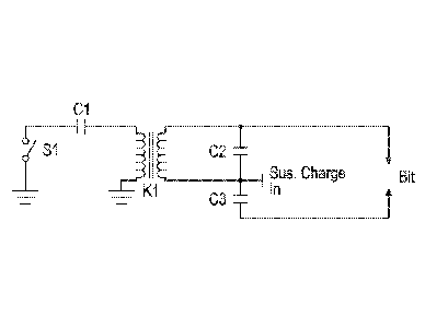
FIG. 3 shows an example circuit comprising transformer windings around the
core K1 to provide
the high voltage pulse and output windings to provide inductive isolation for
the lower voltage
components. When switch Si closes, current flows from lower voltage capacitor
C1 through the primary
winding of the transformer, creating a high voltage pulse on capacitor C2,
which is in turn connected to the
bit in series with capacitor C3. As current flows through the bit from the
establishment of the arc in the rock
from the high voltage pulse, current flows from lower voltage capacitor C3
through the secondary windings
of the transformer. The voltage-time product created by the flow of current
from capacitor C3
through the bit and through the transformer saturates the transformer and
hence provides the high
current pulse to break the rock. FIG. 4 shows an embodiment of a typical high
voltage pulse transformer,
showing the black primary (lower voltage) windings and the secondary (high
voltage) windings tapered
for high voltage insulation and isolation. The core preferably comprises
magnetic materials that have the
desired saturation properties. This transformer is intended to be immersed in
transformer oil for
insulation. After the pulse is over, a reset circuit is often used to bring
the transformer out of saturation
and prepare it for the next pulse. Thus, a saturating transformer in
accordance with the present invention
enables the use of a high impedance high voltage spiker circuit to initially
create conduction in the rock in
conjunction with a lower voltage high current sustainer source to provide
power into the arc to break the
rock. The same piece of equipment, the saturating transformer, preferably
provides both functions.
The core of magnetic material preferably comprises the capability of moving
from high
permeability to low permeability with the correct application of the voltage-
time product in order for the
transformer to possess the desired saturation properties. Magnetic materials
suitable for the saturating
transformer switch include ferrites, Metglae, Supermendur, and other similar
magnetic materials with
magnetic characteristics that facilitate saturation with the application of
the correct voltage-time product.
Embodiments of the transformer magnetic switch of the present invention
combine the functions
of a pulse transformer and a high-voltage high current switch or diode that
isolates the lower voltage
components from the high voltage pulse. The transformer magnetic switch
replaces the high voltage
solid state diode or switch or gas switches that would be used to isolate the
lower voltage components
from the high voltage pulse and control the flow of current from the sustainer
capacitor bank into the arc
-6-
Date Recue/Date Received 2021-02-25
CA 02962002 2017-03-20
WO 2015/042608
PCT/US2014/057060
after arc formation. The switches require isolation from the high voltage
pulse, said isolation is provided
by the inductance of the secondary windings of the magnetic transformer
switch. This is advantageous in
the electro-crushing drill pulsed power circuit because such a switch is
highly immune to damage from a
fault in the circuit. For example, rock is very non-uniform, and the pulses
delivered by the pulsed power
system vary greatly from shot to shot during the drilling process.
Occasionally a shot will produce very
unusual current or voltage waveforms. If solid-state diodes were used for
voltage isolation, they might be
damaged by the unusual shot. A magnetic switch which functions as a diode,
however, is very immune to
damage from unusual events. in addition, the magnetic "diode" can be quite
compact compared to high
voltage solid-state diodes and their protection circuits.
Irk:merino
One of the difficulties with the spiker-sustainer circuit is electrical noise
generated in the circuit
from the spiker pulse. This electrical noise is often sufficient to trigger
the sustainer switch, thus
preventing proper control of the sustainer switch timing by the control
system. In addition, the electrical
noise is sometimes sufficient to damage the solid state trigger switches often
used. Thus it is desirable to
provide a noise immune trigger for turning on the sustainer switch in such a
spiker-sustainer circuit
without upsetting timing from electrical noise and without damage from
electrical noise. An embodiment
of such a trigger of the present invention is preferably configured for use
with a saturating inductor, also
known as a magnetic switch, as the switching element to trigger the sustainer
switch. In embodiments of
this invention, the saturating inductor (magnetic switch) is connected to the
spiker output and conducts a
small amount of current from the spiker output pulse through the magnetic
switch to a ballast capacitor
during the spiker pulse. This current flow, integrated over the desired time
delay for sustainer ignition, will
cause the magnetic switch to saturate creating a trigger pulse to turn on the
sustainer switch.
The time for the magnetic switch to saturate is preferably designed to be the
correct time delay
between onset of the high voltage pulse and turning on the sustainer switch.
After the trigger pulse is
over, a reset circuit is often used to bring the magnetic switch out of
saturation and prepare it for the next
pulse. Thus, a magnetic switch in accordance with the present invention
provides a trigger pulse to turn
on the sustainer switch without susceptibility to electrical noise, either in
timing upset or damage to
components. The timing of the sustainer trigger pulse is preferably determined
by passive components,
-7-
=
WO 2015/042608
PCT/US2014/057060
and is not subject to upset from electrical noise. Once the timing of the
sustainer trigger pulse has been
set by the design of the magnetic switch, it will always be the same for a
given spiker output voltage pulse
profile.
FIG. 5 is a schematic of an embodiment of a magnetic switch trigger for an
electro-crushing drill
switch. Negative voltage signal 2, preferably the spiker output voltage of the
pulse sent to the rock during
the drilling process, is preferably reduced in magnitude through resistor
array 6 and charges capacitor 3
through diode 4 in parallel with magnetic switch 1. When magnetic switch 1
saturates, it inverts the
polarity of capacitor 3 to provide the required positive polarity to trigger
(i.e. turn on) switch 5 through
diode 7. Capacitor 8 is preferably used to manage the pulse shape going to
switch 5.
Although the invention has been described in detail with particular reference
to the disclosed
embodiments, other embodiments can achieve the same results. Variations and
modifications of the
present invention will be obvious to those skilled in the art and it is
intended to cover all such
modifications and equivalents.
-8-
Date Recue/Date Received 2021-02-25