Note: Descriptions are shown in the official language in which they were submitted.
CA 02963167 2017-03-30
WO 2016/050980 1 PCT/EP2015/072874
PRINTING AN ADHESIVE PATTERN ON AN ANTI-FOULING SUPPORT
TECHNICAL FIELD
The present invention relates to the field of grafting a protein onto a
substrate, according to an
optically defined pattern.
BACKGROUND
The publication of international application number WO 2013/135844
(hereinafter "STUDER" or
"the publication") discloses a device for the microstructured grafting of
proteins onto a substrate,
or photochemical printing device. In the publication, a mixture, in aqueous
solution, of a
benzophenone (BP) and of a protein is illuminated in places according to a
pattern on top of a
.. substrate and a durable transfer of the protein at the illuminated places
is obtained, producing the
printing. However, the process described in the publication transfers the
protein onto the
substrate, in the presence of BP and at the same time as the illumination.
This device involves a combination, at the same location, of a lighting device
for illuminating
according to an image of a pattern on the substrate and a microfluidic device
that makes it
possible to convey an aqueous solution simultaneously containing a protein and
a BP. This results
in a problem of bulkiness of the printing system and also a risk of damaging
the protein by the
combined action of the benzophenone and the light from the lighting device.
Ideally, it would be
useful to print a pattern that is only adhesive for the protein, without
adhered protein, onto a
substrate, by means of the lighting system. An actual pattern would
subsequently develop on the
.. substrate, in contact with an aqueous solution of a protein, for example a
fluorescent protein, the
protein attaching preferentially to the illuminated parts in the adhesive
pattern to form the actual
pattern. Such a solution is nevertheless governed, for a protein, by the
availability of a process
capable of producing a latent or subsequently developed adhesive pattern,
which is printed onto a
support covered by a protein anti-fouling layer. A protein anti-fouling layer
is understood to
mean a layer made from a material that has no attachment of proteins to said
layer, on the
timescale of carrying out the printing that it is proposed to produce.
Such a substrate covered by its anti-fouling layer, or anti-fouling substrate,
may be formed in
particular by a support such as a hard support, one example of which is a
glass of optical quality
CA 02963167 2017-03-30
WO 2016/050980 2 PCT/EP2015/072874
which is transparent for the light from the lighting system, or such as a soft
support, one example
of which is a PDMS, the glass or the PDMS being covered by a polymer brush
material, or
polymer attaching as a brush to the support by chains of molecules, such as
PEG and polyNipam.
The polymer chains are, for anti-fouling substrates of this type, attached at
one of their ends to
the support and free at the other end, like the bristles of a brush.
Other techniques such as photolithography applied to a protein anti-fouling
substrate through a
mask using laser ablation of patterns of anti-fouling materials on an anti-
fouling substrate make it
possible in the prior art to obtain anti-fouling supports having patterns that
allow the subsequent
selective grafting of a protein to the substrate, according to the illuminated
zones of the substrate
from which the polymer brush or anti-fouling material has been removed, by
light energy.
It is considered that ablation of material is caused by the illumination of
the substrate and that the
differences in level produced make possible a pseudoscopic image of the
subsequent actual
image. When these differences are observed by the optical phase-contrast
technique which is only
sensitive to the optical path, the adhesive pattern may be attributed in an
equivalent manner to an
ablation of anti-fouling material or to a change in the nature of the material
modifying its optical
index and providing a subsequent preferential adhesion of proteins to the
zones of polymer chains
that have been illuminated. Other techniques that enable the latent image to
be observed (in
particular atomic-force microscopy, ellipsometry, x-ray analysis, etc.) make
it possible in certain
cases to prove that the latent image is due to a complete ablation of the PEG
layer for these
techniques. Such ablation techniques do not therefore make it possible to
produce concentration
gradients, the ablation of the PEG or anti-fouling layer being a priori
complete.
It would finally be desirable to have available a process for producing an
anti-fouling or polymer
brush support having adhesion that is proportional or continuously variable
with the exposure of
the brush to an illumination, according to a pattern, without molecules
necessarily being adhered
to the brush at the same time as the illumination. It would instead be
desirable for these
molecules to be adhered to the brush in a deferred manner.
GENERAL PRESENTATION
The following definitions apply to the present application:
CA 02963167 2017-03-30
WO 2016/050980 3 PCT/EP2015/072874
"Adhesive pattern": denotes a surface pattern according to which certain
molecules, in particular
proteins (and especially antibodies), nanoshells, DNA (deoxyribonucleic acid)
strands or RNA
strands or bacteria are distributed in a time-stable manner on a support
covered by an anti-
adhesive or anti-fouling or polymer brush layer, outside of said adhesive
pattern. Since the
pattern is defined outside of an anti-adhesive or anti-fouling zone or a set
of anti-adhesive or anti-
fouling zones, an adhesive pattern may also be defined on a substrate as a set
of zones or patterns
that are more adhesive for the molecules of interest than the supplementary
surface of the set of
zones on the substrate. A difference in adhesion effect, necessary for the
existence of a pattern,
may be predicted for a polymer brush, without coming into contact with an
aqueous solution of a
molecule, by at least two techniques that are available in the prior art:
- Atomic-force microscopy, which makes it possible to demonstrate a reduction
in the length of
the polymer chains of the brush, such a reduction then causing a reduction in
the anti-adhesive
effect or an increase in the adhesion effect in these zones.
- Phase-contrast microscopy, which makes it possible to demonstrate a
variation in the optical
path through the brush in the most adhesive zones, such a variation then being
associated with an
adhesion effect variation.
"Polymer brush": denotes a nanometric layer (i.e. the thickness of which is on
the nanometer
scale, namely typically between 1 nm and 100 nm) which is anti-fouling, in
particular for
proteins, nanoshells, DNA strands and bacteria, such a nanometric layer being
present at the
surface of a support in order to form an anti-fouling substrate. It is
estimated, at the date of the
present application, that such a brush consists of a set of polymer chains
grafted to the surface of
a support, this set extending in a zone having a thickness of between 1 nm and
20 nm at the
surface of the support for PEG and between 1 nm and 30 nm for polyNIPAM. It is
estimated that
between 1 nm and 20 nm, such a brush has anti-adhesion or anti-fouling
properties, in particular
for proteins, nanoshells, DNA strands or bacteria. A polyethylene glycol or
"PEG" layer or a
poly(N-isopropylacrylamide) or polyNIPAM layer are examples of polymer
brushes.
"Thickness" denotes, for a polymer brush, the measure of the distance to the
support from the
free ends of the polymer chains forming the brush. For example, for PEG, the
thickness of the
layer is controlled by the length of the PEG chains, that is to say the number
of ethylene glycol
CA 02963167 2017-03-30
WO 2016/050980 4 PCT/EP2015/072874
monomers making up these chains. These chains may in particular be inclined
with respect to the
substrate or compressed or modified in any manner similar to an action on the
bristles of a brush
in order to print a relief or a thickness variation on the free surface of the
brush.
Within this context, the invention relates to a process for printing an
adhesive pattern on a
polymer brush extending at the surface of a support forming a nanometric anti-
fouling layer, the
process comprising the following steps:
- placing the layer in contact with a first aqueous solution containing a
benzophenone,
- then illuminating the layer with radiation at a wavelength within the
absorption spectrum of the
benzophenone, according to the pattern and according to a surface energy.
In variants of the process:
- the thickness of the layer is between 1 nm and 20 nm;
- the wavelength is chosen between 300 nm and 400 nm;
- the polymer is a polyethylene glycol (PEG);
- the polymer is a polyNIPAM;
- the support is a glass;
- the support is a PolyDiMethylSiloxane (PDMS);
- the surface energy of the illumination transmitted to the PEG layer is
between 10 mJ/mm2 and
1000 mJ/mm2;
- the surface energy of the illumination transmitted to the polyNIPAM layer is
between 100
mJ/mm2 and 10 000 mJ/mm2;
- the Young's modulus of the PDMS support is less than 15 kPa.
The invention also relates to a process as above, for printing a pattern of a
protein on the polymer
brush, comprising the following additional steps:
- rinsing to eliminate the contact between the layer and the first solution,
CA 02963167 2017-03-30
WO 2016/050980 5 PCT/EP2015/072874
- then placing the layer in contact with a second aqueous solution containing
the protein.
The invention also relates to a process as above, for printing a pattern of
nanoshells on the
polymer brush, comprising the following additional steps:
- rinsing to eliminate the contact between the layer and the first solution,
- placing the layer in contact with a second solution containing the
nanoshells.
The invention also relates to a process as above, for printing a pattern of
DNA strands on the
polymer brush, comprising the following additional steps:
- rinsing to eliminate the contact between the layer and the first solution,
- placing the layer in contact with a second solution containing the DNA
strands.
The invention also relates to an application of the process for printing an
adhesive pattern, to the
production of an adhesive pattern having an adhesion gradient at the surface
of the support, by
spatial variation of the surface energy.
BRIEF DESCRIPTION OF THE DRAWINGS
The invention will be better understood in connection with the list of figures
below, wherein:
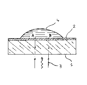
- figure 1 represents, in cross section, an anti-fouling substrate composed of
a glass support and a
layer of material that is anti-fouling, in particular for proteins, nanoshells
or DNA strands, that is
to say a polymer brush grafted or attached to the support. The substrate is
covered with a drop of
an aqueous solution containing benzophenone over all or some of the polymer
brush. A zone AB
of the layer, covered with benzophenone, is illuminated through the support
(through the drop
would also be practicable) via radiation comprising wavelengths within the
absorption spectrum
of benzophenone, i.e. radiation between 300 nm and 400 nm.
- figure 2 represents the substrate rinsed of the drop from figure 1 and
having a latent image
represented in a illustrated manner by a hollow in the surface of the anti-
fouling material at the
zone AB. Such a material is capable of being used to print in particular a
pattern of a protein, of
nanoshells or of DNA or RNA strands according to a pattern corresponding to
the surface of the
zone AB. Specifically, the illumination of the polymer brush in the presence
of benzophenone
83993886
6
potentially renders the polymer brush adhesive in the zone AB and enables the
subsequent adhesion
in particular of a protein, of nanoshells or of DNA strands, by subsequently
placing the polymer
brush layer in contact, respectively, with in particular a solution of the
protein, a solution of
nanoshells or of DNA strands. An illumination according to a set of zones like
AB thus enables the
production of an adhesive pattern or an adhesive pattern of molecules on a
polymer brush, for
molecules for which the brush is normally non-adhesive.
DETAILED DESCRIPTION OF EXAMPLE(S)
In some embodiments disclosed herein, there is provided a process for printing
an adhesive pattern
on a polymer brush extending at the surface of a support forming a nanometric
anti-fouling layer,
the process comprising the following steps: placing the layer in contact with
a first aqueous solution
containing a benzophenone, then illuminating the layer with a radiation at a
wavelength within the
absorption spectrum of the benzophenone, according to the pattern and
according to a surface
energy, thereby creating an adhesive pattern which is a zone or a set of zones
on the polymer brush
that are more adhesive for molecules of interest than the supplementary
surface of the zone or set of
zones on the polymer brush, the adhesive pattern being a hollow latent pattern
in the polymer brush
and not being covered by the molecules of interest but left bare.
In a first embodiment, disclosed with reference to figure 1 for the reference
numbers between
parentheses, are an anti-fouling substrate composed of a glass support (1) and
a layer (2) of a
polymer brush material which is, in this first embodiment, PEG or polyNIPAM.
In this first embodiment, radiation (3) illuminates the layer (2) over a zone
AB (AB), here through a
support (1) chosen to be transparent for the radiation used, a drop (4) of an
aqueous benzophenone
solution is deposited on the layer (2) covering the zone AB (AB). In an
equivalent manner, it would
be possible to illuminate the layer through the drop (4), over the same zone
AB.
The radiation used comprises at least one wavelength within the absorption
spectrum of
benzophenone, which spectrum usefully extends in practice between 300 nm and
400 nm.
Preferentially, within this range use will be made of radiation having a
wavelength of less than
390 nm, in this case the exposure time of the layer to the radiation will be
minimized.
Date Recue/Date Received 2022-04-04
83993886
6a
The lower the absorption of benzophenone at the chosen wavelength, the greater
the power of the
light source will have to be or the longer the exposure time of the
illuminated zone will have to be,
the dose of the radiation received, equal to the product of the lighting power
and the exposure time
to the light, being the parameter governing the obtaining of the effect of the
invention.
Since no protein to be grafted is in solution, the radiation will if necessary
be of higher power than a
power that gives rise to the destruction of a protein to be subsequently
grafted and will only be
limited by the surface density of light energy accepted by the layer, without
degradation. However,
the presence of benzophenone makes it possible, for PEG, to use optical powers
10 to 100 times
lower than for ablation or masking techniques.
Date Recue/Date Received 2022-04-04
CA 02963167 2017-03-30
WO 2016/050980 7 PCT/EP2015/072874
An energy density between 10 mJ/mm2 and 1000 mJ/mm2 can thus be used to obtain
the
appearance of an adhesive pattern on PEG. The invention may thus be satisfied
with a source that
produces an illumination of 2 mVV over a square having sides of 400 microns
for a wavelength of
an ultraviolet line at 372 nm from a semiconductor laser. For polyNipam on a
PDMS support, a
usable energy density is between 100 mJ/mm2 and 10 000 mJ/mm2. The same
semiconductor
laser source may again be used by simply multiplying the exposure times for
PEG by 10.
In a first step of the process of this embodiment, the anti-fouling substrate
is placed in contact
with a drop of aqueous benzophenone solution, then in a second step a zone AB
of the anti-
fouling layer of the substrate is illuminated with the ultraviolet light
source.
Any optical system enabling the energy of the source to be focused on the zone
AB or on a set of
zones at the same time can be used and such systems are known from the prior
art. A microscope
with a micromirror array can thus be envisaged for producing the lighting
system for this
embodiment. Similarly, the drop may be replaced by a film of aqueous
benzophenone solution,
brought into contact with the layer, then rinsed after illumination by known
microfluidic means.
Figure 2 represents the polymer brush formed as a nanometric layer, thus
rinsed of the drop of the
benzophenone solution and provided, in an illustrated manner, with a hollow
latent pattern that is
itself also nanometric with regard to its depth, in the zone AB. In order to
be developed, this
hollow or latent pattern needs to be subsequently brought into contact with
molecules or
molecular assemblies capable of adhering to the support at this hollow in a
polymer brush
.. (proteins, nanoshells, DNA strands, bacteria, etc.), the adhesion of these
molecules according to
the latent pattern then takes place in the presence of these molecules in
aqueous solution, at the
zones of the layer which have been illuminated (here AB) in the presence of
benzophenone. The
adhesion of molecules takes place without provision of light energy. The
molecules are simply
adsorbed on the polymer brush at the latent pattern or adhesive pattern. An
actual pattern of
molecules is thus formed on the brush. In particular if the molecules are
fluorescent, it is possible
to then make an image thereof by techniques known in the prior art in order to
demonstrate the
result of the adhesion.
However, even without bringing into contact with an aqueous solution, for
example a solution of
proteins, it is possible to predict, after insolation of the brush, whether
the effect of the invention
CA 02963167 2017-03-30
WO 2016/050980 8 PCT/EP2015/072874
will be obtained, independently of the production of a subsequent actual
pattern, by measuring,
after illumination, whether there are hollows of nanometric depth in the brush
at the illuminated
locations using an atomic-force microscope (AFM), or by observing whether
there are optical
path variations in the brush, optically, by phase-contrast microscopy at these
same locations. It is
thus possible to select, without other experimentation, the polymer brushes
suitable for the
process of the invention, in particular as being those for which a reduction
in the length of the
polymer chains of the brush is observed after illumination in the presence of
benzophenone.
In a second embodiment of the invention, the device from figure 2 is brought
into contact with an
aqueous solution of a protein or an aqueous solution of nanoshells. The choice
of the nature of
the proteins or of the nanoshells is made from the proteins and nanoshells
capable of adhering to
the support in order to obtain the most durable possible actual image.
It is thus possible, with the process of this second embodiment, to obtain an
actual image of the
zone AB for example by using a fluorescent protein, but more generally a
pattern of a protein on
the protein anti-fouling substrate that was used. Furthermore, the properties,
under illumination,
of the anti-fouling substrates make it possible to produce a fluorescence
having a value that varies
continuously with the illumination or the dose of optical radiation received
by the zone AB and
more generally a concentration of proteins, of nanoshells or of DNA strands
that varies
continuously with the illumination in this zone, even if this zone corresponds
to the resolution
limit of the optical lighting system, without recourse to densities of binary
points to simulate
variable concentrations of proteins.
It is thus possible to apply the invention to the production of adhesion
gradients in a
concentration direction for example of a protein, of nanoshells or of DNA
strands, along the
surface of the substrate or of the anti-fouling layer, by aligning several
zones of type AB end-to-
end and by varying the surface energy delivered to these zones, for example by
illuminating them
with variable surface zones (in J/m2) , during the step of illuminating the
polymer brush in the
presence of benzophenone or of printing the latent image or adhesive pattern.
For example, a continuously variable adhesive effect for proteins has been
obtained by variable
dose illumination in the presence of benzophenone on a PEG brush, for a
thickness reduction of
between 0 nm reduction (no adhesion or outside-pattern zone) and 2 nm
reduction (maximum
CA 02963167 2017-03-30
WO 2016/050980 9 PCT/EP2015/072874
adhesion) for PEG polymer brushes having a thickness estimated at 5 nm outside
of the adhesion
zones.
In the embodiments presented, a concentration range in millimoles of
benzophenone per liter of
aqueous solution (mmo1/1) from 5 mmo1/1 to 50 mmo1/1 was used.
The invention is industrially applicable within the field of substrate
production for printing
adhesive patterns of a protein on a polymer brush.