Note: Descriptions are shown in the official language in which they were submitted.
CA 02963440 2017-03-31
WO 2016/054430
PCT/US2015/053581
EXERCISE APPARATUS AND METHOD
Cross-Reference to Related Application
[0001] This application claims the benefit of US Provisional Application
No.
62/058,570, filed on 1 October 2014, and which application is incorporated
herein by
reference. A claim of priority is made.
Technical Field
[0002] Various embodiments described herein relate to an exercise
apparatus and a
method for using the same. More specifically, the exercise apparatus relates
to a training
device used to drill football players such as grids used for agility training.
Background
[0003] Athletes frequently will perform various drills to try and improve
their
physical performance. In many cases the drills used do not directly involve
the sport for
which the athlete is training. For example, many football trainers will spend
time lifting
weights to increase strength, but no one lifts weights during an actual
football game. It is
well known that many athletes will perform better when they develop certain
skills. It is also
true that specific drills can be utilized to develop particular skills and
capabilities.
[0004] Many athletes will use various drills to improve fundamental
motion skills.
One type of implement which can be used is an exercise ladder. Many different
exercise
ladders are available, and they can be used in a wide variety of drills to
improve the agility,
speed, coordination., balance, quickness and other traits of an athlete. In
some cases, several
tires can be set in a line, and an athlete will run through the tires while
stepping in the middle
hole as they progress. Alternatively, exercise ladders can be laid on a
playing surface and the
athlete will perform various drills while moving through the ladder.
[0005] Generally, exercise ladders are one or two squares wide. These
exercise
ladders can be many squares long and they appear somewhat like a standard
ladder with
rungs lying on the ground. Exercise ladders can lie flat on the ground where
they merely
serve to mark a particular pattern on the playing surface, or alternatively
they can be
suspended at some distance above the ground. Frequently, when the exercise
ladders are
1
CA 02963440 2017-03-31
WO 2016/054430
PCT/US2015/053581
suspended the athlete will be performing drills which encourage lifting the
foot before each
foot placement.
[0006] There are a great many different types of drills which are
possible with a
simple exercise ladder device. Many of the drills aid an athlete to develop
quick motion of
the feet, improve coordination, and shorten start time. This can make an
athlete quicker and
more agile on their feet. For many sports, an athlete may try to increase the
speed of the
starting motion in any direction from where they are standing. The athlete may
desire to
begin moving quickly straight behind them or straight forward, or to the left
or right, or
anywhere in between. The athlete desires a quick start in any possible
direction.
[0007] One of the best ways to improve performance is to practice the
desired motion.
Practicing starting in every possible direction can aid an athlete in gaining
a quicker start,
regardless of the direction in which the athlete will be moving. in many
sports, agility and
quickness training is one aspect of an overall training program. It is not
uncommon for
exercise ladders to be used for agility and quickness training for a portion
of a practice
period, and then other drills and practice techniques are used for the rest of
the practice
period.
[0008] Most of the patterns result in front to back motion of the feet or
side to side
motion of the feet. Such drills are somewhat limiting in the amount of benefit
produced by
the drill. Most of the ladders come in two forms. One form of ladder is a rope
that lays on
the ground or is slightly elevated from the ground. The rope is tied to form a
ladder. Another
form of ladder are squares of material. The squares are laid on a floor or on
a field in a
desired pattern. Several companies vary the shape from a square of material to
octagonally-
shaped material or hexagonally-shaped material. The squares, octagons, or
hexagons include
openings of sufficient size so a foot can be placed in the shape. Still, the
various shapes are
ladders that drill forward, backward, and side to side motions.
[0009] Some of the shapes are made from light plastics. One disadvantage
of light
plastic ladder elements is that they are easily knocked out of a pattern. This
can happen
especially if an athlete misplaces a foot during a drill and strikes the light
plastic ladder
element. A further disadvantage of these ladder elements is that many times
the element is
kicked or otherwise moved and, because of the light weight, the plastic
element rapidly
accelerates and knocks out other "squares" in the pattern originally laid out.
In some
instances, one square bumps into one or more other "squares' and sends them
flying much
like a cue ball hitting the racked balls at the start of a game of billiards.
The "squares" go
every which way. The drill has to be stopped while the squares are gathered
and replaced
into the pattern. This effect may be worse when the "squares" are actually
hexagons or
2
CA 02963440 2017-03-31
WO 2016/054430
PCT/US2015/053581
octagons since less material along a side is in contact with adjacent hexagons
or octagons.
With less material acting on the sides of the squares, the hexagons and
octagons will be more
likely to become displaced and more likely to knock out other ladder elements
in a set
pattern.
Brief Description of the Drawings
[0010] The embodiments will be readily understood by the following
detailed
description in conjunction with the accompanying drawings, wherein like
reference numerals
designate like structural elements, and in which:
[0011] FIG. 1 is a top view of trapezoidally-shaped ladder element,
according to an
embodiment.
[0012] FIG. 2 is a perspective view of a ladder element, according to an
example
embodiment.
[0013] FIG. 3 is a schematic view of a kit that can be used to form an
exercise
ladder, according to an example embodiment.
[0014] FIG. 4 is a schematic view of another kit that can be used to form
an exercise
ladder, according to an example embodiment.
[0015] FIG. 5 is a perspective view of an exercise ladder formed from
trapezoidally-
shaped ladder elements, according to an example embodiment.
[0016] FIG. 6 is a perspective view of an exercise ladder formed from
trapezoidally-
shaped ladder elements, according to an example embodiment.
[0017] FIG. 7 is a perspective view of a hurdle that can be used with the
trapezoidally-shaped ladder elements, according to an embodiment.
[0018] FIG. 8 is a top schematic view of a number of patterns made with
the
trapezoidally-shaped ladder elements, according to an embodiment.
[0019] FIG. 9 is a perspective view of a number of shaped ladder elements
placed
side by side to form a curve, according to an embodiment.
Detailed Description
[0020] In the following paper, numerous specific details are set forth to
provide a
thorough understanding of the concepts underlying the described embodiments.
It will be
apparent, however, to one skilled in the art that the described embodiments
may be practiced
without some or all of these specific details. In other instances, well known
process steps
3
CA 02963440 2017-03-31
WO 2016/054430
PCT/US2015/053581
have not been described in detail in order to avoid unnecessarily obscuring
the underlying
concepts.
[0021] FIG. 1 is a top view of trapezoidally-shaped ladder element 100,
according to
an embodiment. FIG. 2 is a perspective view of a ladder element 100, according
to an
example embodiment. Now referring to both FIGs. 1 and 2, the trapezoidally-
shaped
ladder element 100 will be further detailed. The trapezoidally-shaped ladder
element 100
includes a long base 110 and a short base 112. The long base 110 is parallel
to the short
base 112. The long base 110 is longer than the short base 112. The
trapezoidally-shaped
ladder element 100 also includes a first side or lateral leg 120 and a second
side or lateral
leg 122. In the embodiment shown, the first side or lateral leg 120 and a
second side or
lateral leg 122 are substantially equal in length. This is an isosceles
trapezoid. The
trapezoidally-shaped ladder element 100 need not be an isosceles trapezoid. It
is fully
contemplated that a trapezoidally-shaped ladder element 100 could have a first
side or leg
which is unequal to a second side or leg. This could be advantageous as this
would increase
the shapes that could be formed when at least two or more trapezoidally-shaped
ladder
elements 100 are placed together.
[0022] As shown in FIG. 2, the trapezoidally-shaped ladder element 100 is
formed
of a flexible material, such as rubber or similar material. The flexible
material allows a
ladder (500 or 600, shown in FIGs. 5 and 6) to be formed over varying terrain.
Each of the
ladder elements 100 is formed as an independent piece. In other words, one
ladder element
100 does not interlock or connect to the adjacent ladder element 100. This
allows one or
move individual ladder elements to be kicked or moved out of place without
affecting other
ladder elements. If an athlete or other person using the training device would
happen to
contact an individual ladder element 100, the individual ladder element and
possibly some
units adjacent thereto would just move. This could easily be fixed by a coach
or other
person. Since all the units forming the ladder are not interconnected, only a
few of the
ladder elements to move when one or more trapezoidally-shaped element 100 are
displaced
inadvertently. The ladder elements 100 that moved or were kicked out of
position, can be
picked up and placed to a desired position within a ladder formed. Thus, a
formed ladder
can be fixed quickly so that others can continue on with the drill or drills
with minimal
interruption. It should be noted that this is an advantage since there may be
limited time on
the field or in a practice facility. In that case, it is vitally important to
keep the athletes
moving so that all can be drilled on the skill. Less time will be wasted when
compared to
other systems which are all tied together.
4
CA 02963440 2017-03-31
WO 2016/054430
PCT/US2015/053581
[0023] In one embodiment, the rubber material ranges in thickness from
about 4mm
to about 10 mm. In another embodiment, the rubber material ranges in thickness
from
about 5.5 mm to about 8.5 mm. 10 mm. In still another embodiment, the rubber
material
ranges in thickness from about 6.5 mm to about 7.5 mm. 10 mm. In yet another
embodiment, the rubber material is about 7 mm. The material is generally 12 mm
to 40 mm
in width. In other embodiments, the material is 20 to 30 mm wide. In still
another
embodiment, the width is around 25 to 26 mm. In another embodiment the width
of the
legs and bases is in the range of half of the ranges set forth above. The
width could be
anywhere from 13 to 19 mm. A trapezoid sized so that an athelete's foot fits
within the
trapezoid then has a weight so that it is light enough to move around and
position easily into
various patterns, and light enough so that a number of the trapezoidally
ladder elements can
be moved at once, such as in a gym bag or other equipment bag. The ladder so
dimensioned
is also high enough so that if contacted with the foot, the athlete will know
that the foot
placement was off. Advantageously, the ladder so dimensioned is heavy enough
so that it
will generally move slightly when contacted but will not move at rapid speed
and dislodge a
multitude of other pieces. When a trapezoidally shaped ladder element is
moved, many less
pieces will be effected and the piece or pieces can be repositioned with ease.
In one
embodiment, the the trapezoidally shaped ladder element weighs 1.2 lbs. In
other
embodiments, the the trapezoidally shaped ladder elements can weigh between
0.8 lbs to 1.8
lbs. Of course, this depends on the material used and the actual dimensions of
the piece.
This allows a trainer to carry 15 the trapezoidally shaped ladder elements
easily as they
would weigh between 12 lbs and 27 lbs.
[0024] This is in contrast to a ladder formed of interconnected elements
where
contacting the ladder can ruin all or a majority of the ladder. Exercise
systems that are
interconnected so that the ladder is essentially one unit, require a much
longer time to
reposition. In addition, a ladder of light pieces in a pattern may fly apart
if one is contacted.
In either case, when many of the pieces of a ladder are bumped out of place
more time is
needed to reposition the pieces. This wastes time and prolongs the waiting
time for an
athlete to get back to the drill.
[0025] In one embodiment, the trapezoid is formed with a first base that
is 20"long
and a second base that is 13" long. The legs or lateral sides of the trapezoid
are also each
20" long. Characterized in another way, the trapezoid is an isosocles
trapezoid with sides
equal in length. Some describe this as a 3-sides equal trapezoid. The first
base can be in
the range of 10" to 16", the second base can be in the range of 16" to 24"
long. Of course
the legs would have a similar range in this embodiment. The trapezoidally
shaped ladder
CA 02963440 2017-03-31
WO 2016/054430
PCT/US2015/053581
element does not have to be an isosocles trapezoid. In addition, it is
contemplated that the
dimensions can be varied such that the three sides are not necessarily equal.
The two
important factors are that the opening in the ladder element has to be
sufficiently large to
receive a users shoe or portion of a shoe. In addition, the shape must have a
large enough
angle so that the curve formed from laying a number of the trapezoidally
shaped ladder
elements forms a curve having a desired radius. If the radius is too long, the
curve will be
too gentle to be effective. If the radius of the curve formed is too short,
the benefits are also
limited. The advantage to the athlete is learning how to twist and accelerate.
Ladder drills
are really a series of stops and accelerations. When passing through a curve,
the athlete
must stay down in an athletic position. The drills around curves teach
athletes how to twist
and accelerate while staying in the athletic position. The drills help to
develop the muscles
necessary for this acceleration. In addition, the drills can be done on both
the inside of the
curve formed and on the outside of the curve formed. The movements on the
outside will
be much faster. So the athlete may begin on the inside curve and progress to
the outside
curve.
[0026] The radius of the curve formed by placing the shaped ladder pieces
adjacent
one another is related to the angles associated with the trapezoid. The angle
between the
long base and one of the legs of the trapezoid is in the range from .72 to 82
degrees, in one
embodiment. In another embodiment, the angle between the long base and one of
the legs
of the trapezoid is in the range from .75 to 79 degrees. In yet another
embodiment, the
angle is in the range of 76.5 to 77.5 degrees. In still another embodiment,
the angle is
substantially 77 degrees. Angles in the above ranges for a curve that is
within a range
where all the athletic benefits are gained. This also is an angle that is
about right in terms of
the amount of space needed to make the various patterns.
[0027] FIG. 3 is a schematic view of a kit 300 that can be used to form
an exercise
ladder (shown in FIGs. 5 and 6), according to an example embodiment. The kit
300 shown
in figure 3 includes a number or plurality of trapezoidally shaped elements
100. The kit 300
can be supplemented with other kits at a later time. As shown in this
embodiment, all the
trapezoidally shaped elements 100 or approximately the same size and have
approximately
the same angles between the sides. Furthermore, the trapezoidally shaped
elements 100 are
all isosceles trapezoids. It should be noted that in other kits trapezoidally
shaped elements
of different sizes can be included. In addition, it should be noted that
irregular or non-
isosceles trapezoid's can also be included in a kit, such as kit 300.
[0028] FIG. 4 is a schematic view of another kit 400 (shown in FIGs. 5
and 6) that
can be used to form an exercise ladder, according to an example embodiment.
The kit 400
6
CA 02963440 2017-03-31
WO 2016/054430
PCT/US2015/053581
includes a plurality of trapezoidally shaped elements 100 as well as a
plurality of
rectangularly shaped elements 410. As shown in this embodiment, all of the
trapezoidally
shaped elements 100 are similarly shaped. All of the trapezoidally shaped
elements are also
isosceles trapezoids. It should be noted that irregular trapezoidally shaped
elements can
also be included as well as trapezoidally shaped elements that are of
different sizes. This
would allow for more flexibility in forming ladders or exercise ladders. As
noted above, the
kit also includes rectangularly shaped elements 410. As shown, all of the
rectangularly
shaped elements 410 are of the same size. It should be noted that in other
kits the
rectangularly shaped elements 410 can have different shapes. For example, the
rectangles
could be larger or smaller, the rectangles could be square, or the rectangles
maybe
elongated.
[0029] FIG. 7 is a perspective view of a hurdle 700 that can be used with
the
trapezoidally-shaped ladder elements 100, according to an embodiment. The
hurdle 700
includes a main body 710 that has a length about equal to or less than the
length of the legs or
lateral sides of the trapezoidally-shaped ladder elements 100. The hurdle 700
also includes
an anchor portion 720. The anchor portion 720 is formed at an angle with
respect to the
plane of the main body 710 of the hurdle 700. The anchor portion 720 and the
main body can
be formed so that the anchor portion 720 is at a fixed angle with respect to
the main body
710. In one embodiment, the fixed angle is substantially 90 degrees. In
another embodiment,
the anchor portion 720 and the main body 710 can be attached via a living
hinge, especially if
the hurdle is made from a plastic material. The hurdle can range in height
from 1" to 20". In
one embodiment the kit discussed above can have a single type of hurdle 700.
It is also
contemplated that several hurdles having different heights could be included
in a kit. The
hurdles could be low, which would be 2-3" high; medium, which would be 6_8"
high; and
high, which would be 10-12" high. Of course other different heights of hurdles
could be
placed in a kit.
[0030] In operation, the anchor portion would be placed beneath one edge
of the
trapezoidally shaped portion, such as under one of the lateral legs or one of
the bases. The
portion of the ladder would hold the main body in an upright position for
various drills where
leg lifting to a desired height is desirable. Of course, some patterns have
the lateral side of
one ladder element abutting another lateral side of another ladder element.
The hurdle 700
would be placed between the two trapezoidally shaped elements and the anchor
portion 720
would be captured beneath one or the other of the trapezoidally shaped ladder
elements 100.
The width of the anchor portion would be about equal to the width of one of
the legs or bases
of the trapezoidally shaped ladder element 100. It could be wider as well. The
anchor
7
CA 02963440 2017-03-31
WO 2016/054430
PCT/US2015/053581
portion 720 should not be so wide that it would substantially occupy the open
area of the
trapezoidally shaped ladder element 100. It is contemplated that the hurdle be
made of a
flexible plastic material that will yield when hit when the athlete fails to
raise a foot high
enough. Depending on the specific material selected for the hurdle 700, the
anchor portion
720 could present a slippery surface which could pose an unwanted safety
hazard to the
person being drilled. If the width is limited, the anchor portion 720 will be
substantially
covered by one of the legs or bases of the trapezoidally shaped element 100.
[0031] FIG. 5 is a perspective view of an exercise ladder 500 formed from
trapezoidally-shaped ladder elements 100, according to an example embodiment.
As shown,
the trapezoidally shaped ladder elements 100 can be arranged to form an S-
shaped ladder
500. The trapezoidally shaped ladder elements can be laid so that the
elongated base of one
element is substantially aligned with the short base of another trapezoidally
shaped ladder
element 100. This can be continued for as long as a straight line ladder is
desired. The
trapezoidally shaped ladder elements 100 can be as positioned so that the
short base of
adjacent trapezoidally shaped ladder elements 100 are positioned proximate one
another.
When this is done, a curve or turn can be formed in the ladder element 100.
This is
advantageous in that athletes or other people undergoing drills are taught to
move around
curves and the like. In addition, it is also an advantage as it introduces
variety into an
athlete's drill or exercise.
[0032] FIG. 6 is a perspective view of an exercise ladder 600 formed from
trapezoidally-shaped ladder elements 100, according to an example embodiment.
The
exercise ladder 600 formed is in an hourglass shape. Again, to form curves the
short bases
112 of the individual trapezoid units are placed next to each other to form a
curved or non-
straight portion of the exercise ladder 600. Similarly the long base portions
110 of the
individual trapezoid units 100 are also placed adjacent or next to one another
to form the
outside edge of the curve. Again, should be noted that the types of formations
or patterns that
can be formed using a trapezoidally shaped individual element 100 are
essentially limitless.
All sorts of curves can be employed in the formations.
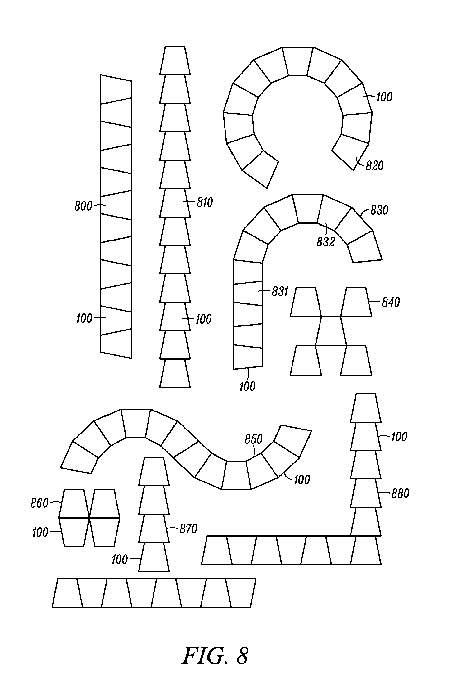
[0033] FIG. 8 is a top schematic view of a number of patterns made with
the
trapezoidally-shaped ladder elements 100, according to other embodiments.
Pattern 800
shows that a straight line can be made by placing the trapezoidally shaped
ladder elements
100 adjacent to one another with the lateral sides abutting one another. The
trapezoidally
shaped ladder elements 100 are laid so that the short base of one element is
beside the long
base of another element. Pattern 810 shows another straight line pattern in
which the short
base of one trapezoidally shaped ladder element 100 is positioned near or
adjacent to the long
8
CA 02963440 2017-03-31
WO 2016/054430
PCT/US2015/053581
base portion of another trapezoidally shaped ladder elements 100. Pattern 820
shows the
trapezoidally shaped ladder elements 100 positioned through about 270 degrees
of a circle.
The curve is formed by laying the trapezoidally shaped ladder elements with
the legs or
lateral sides of each touching an adjacent trapezoidally shaped ladder element
100. The short
bases are also positioned near one another. The above are some of the basic
patterns. Many
of the remaining patterns shown are combinations of the above. For example,
the pattern 830
is formed with a straight portion 831 and a curved portion 832. Pattern 840
shows a
hopscotch pattern formed of five trapezoidally shaped ladder elements 100 that
have corners
of each element touching corners of the other elements. Pattern 850 has a
first curved portion
851 that opens into a second curved portion 852. Pattern 860 is a four square
pattern having
two trapezoidally shaped ladder elements 100 with the adjacent long bases of
each
trapezoidally shaped ladder elements touching one another. Two more
trapezoidally shaped
ladder elements 100 are laid out in a similar pattern and placed next to the
first two
trapezoidally shaped ladder elements 100 to form the four "square" pattern.
The last two
patterns 870, 880 have a straight portion such as that shown in pattern 800
and another
straight portion such as that shown in pattern 810. The two straight patterns
are laid
substantially perpendicular with one another.
[0034] The trapezoidally shaped ladder elements 100 are a new game
changing
agility, mobility and exercise product. The trapezoidally shaped ladder
elements are more
than a replacement or improvement of a traditional or conventional ladder. It
is a leap
forward in functional agility, mobility and exercise application. The patterns
that can be
created provide drills and exercises that teach athletes how to move
correctly. The fact that
these can be easily set up to go around a curve or to form a curve drill or
exercise the feet,
knee and hips in a rotational sequence that straight ladders simply do not
teach. Movements
from these rotational motions and sequences are an athelete's safest, and most
explosive.
These motions are also the least understood and least drilled upon. The the
trapezoidally
shaped ladder elements offers athletes and trainers the best opportunity to
develop, among
other things, speed, explosiveness, deceleration, hip mobility, and athletic
position. For
example, an athlete must drop into a deeper athletic position when negotiating
a pattern of the
trapezoidally shaped ladder elements set up to form a curve.
[0035] FIG. 9 is a perspective view of a number of shaped ladder elements
100 placed
side by side to form a curve 900, according to an embodiment. The ladder
elements 100 are
open in the middle and are bound by a rubber or flexible boarder. The ladder
elements have a
long base and a short base dimensioned as set forth above. The legs of the
trapezoidally
shaped ladder elements 100 are placed next to or adjacent to the leg of
another trapezoidally
9
CA 02963440 2017-03-31
WO 2016/054430
PCT/US2015/053581
shaped element as shown in FIG. 9. The long bases are placed on one side and
the short
bases are place on the other side to form a curve having a plurality of shaped
ladder elements.
As can be seen, the shaped ladder elements 100 are formed of rubber and have a
thickness of
about 7 mm. There is an angle between the long base and the leg which is the
same for an
isosocles trapezoid. This also fixes the angle between the short base and the
leg. The angle
in the embodiment shown is approximately 77 degrees. A shaped ladder element
with this
angle makes a curve which provides a balance between the ability to provide
the proper
spacing for athletes to step in and out of the shaped ladder elements and the
need for
compactness. The angle discussed above can be varied, but it can also be seen
that the size
of the angle is related to the size or radius of the curve formed. FIG. 9
shows that the legs of
the trapezoidally shaped ladder elements abut one another to form a curve.
[0036] In one embodiment, the the trapezoidally shaped ladder elements
are made
from 100% recycled rubber. The the trapezoidally shaped ladder elements are
configurable,
durable and multi-purpose. They also work on virtually any surface, such as
sand, grass,
wood, tile, astroturf, and the like. An endless number of designs can be
formed with the the
trapezoidally shaped ladder elements. The designs can be tailored by trainers
for different
atheletic endeavors. A tennis player can be trained one way with a set of
patterns and
football running backs can be trained in other ways using the same set of the
trapezoidally
shaped ladder elements set in a different array of patterns. The trapezoidally
shaped ladder
elements can be used for functional development, strength building, or
rehabilitation. The the
trapezoidally shaped ladder elements also can replace other devices so a
trainer can cut down
on the number of training devices they need to use. For example, the the
trapezoidally
shaped ladder elements can be set to teach or drill directional function that
replaces cones.
The the trapezoidally shaped ladder elements work on strength through
repetition. Patterns
can be set up for the following: hip mobility, torsional strength, ACL injury
prevention, shin
splint prevention, proper foot placement, knee follows toes, athletic position
training, and
functional cardio. The trapezoidally shaped ladder elements can also be used
to rehabilitate
athletes after an injury. One example of the use of the trapezoidally shaped
ladder elements
is for ACL injury rehabilitation.
[0037] It should be noted that the ladder elements discussed above are
described as
trapezoidally shaped. Polygons having legs that are at angles less than 90
degrees can be
formed to have the same effect. For example, triangles can be formed with two
of the interior
angles being about 77 degrees. Another variation would be a polygon that
included three
sides of a trapezoid and had a substitute for the shorter base, such as two
segments joined at a
mid-point. Other polygons could also be within the scope of the invention.
Different
CA 02963440 2017-03-31
WO 2016/054430
PCT/US2015/053581
polygons that have long sides like the legs of the trapezoid that make an
angle less than
perpendicular would achieve a similar result. These are also contemplated by
this invention.
[0038] Although not shown, should be noted that straight sections or
rectangular
portions (such as 410 shown in figure 4) can also be used or made part of a
kit. In this way,
long straight portions can be formed. In addition, it should be noted that the
angle of the
sides with respect to the base of the trapezoidally shaped units can be
changed. In addition,
the size of the trapezoidally shaped units can also be changed to accommodate
different shoe
sizes of athletes. In addition, different colors may be used to indicate
different movements in
drills. For example, most may be black and there may be a few read trapezoids.
In the red
trapezoids, maybe the athlete has to do a double tap of the foot or other
dissimilar movement.
[0039] The foregoing description, for purposes of explanation, used
specific
nomenclature to provide a thorough understanding of the invention. However, it
will be
apparent to one skilled in the art that the specific details are not required
in order to practice
the invention. Thus, the foregoing descriptions of specific embodiments of the
present
invention are presented for purposes of illustration and description. They are
not intended to
be exhaustive or to limit the invention to the precise forms disclosed. It
will be apparent to
one of ordinary skill in the art that many modifications and variations are
possible in view of
the above teachings.
[0040] The embodiments were chosen and described in order to best explain
the
principles of the invention and its practical applications, to thereby enable
others skilled in
the art to best utilize the invention and various embodiments with various
modifications as
are suited to the particular use contemplated. It is intended that the scope
of the invention be
defined by the following claims and their equivalents.
[0041] While the embodiments have been described in terms of several
particular
embodiments, there are alterations, permutations, and equivalents, which fall
within the scope
of these general concepts. It should also be noted that there are many
alternative ways of
implementing the methods and apparatuses of the present embodiments. It is
therefore
intended that the following appended claims be interpreted as including all
such alterations,
permutations, and equivalents as fall within the true spirit and scope of the
described
embodiments.
11