Note: Descriptions are shown in the official language in which they were submitted.
FURNITURE ITEM WITH LEAF MECHANISM
The invention relates to a mechanism for leaves, in particular to a motion
system for sliding leaves, and to the furniture item comprising the mechanism.
On some furniture item there are mounted sliding leaves to avoid the
disadvantages of the hinged ones, i.e. less closing surfaces for a compartment
and bulky opening radii. Each sliding leaf is supported by a pair of brackets
connected to carriages with wheels sliding inside a rail, formed in a metal
section,
arranged on the ceiling and/or on the bottom of the furniture item.
The brackets and the carriages are not sufficient to support and guide the
leaf, and a movable arm, mounted inside the compartment that the leaf closes,
is
added.
Such arm is extendable linearly, in a direction perpendicular to the leaf, to
allow it to get out cantilevered with respect to the furniture item, and has L-
shape
with a wheel at one end. The L-shape serves to increase the horizontal stroke
of
the leaf, nonetheless a problem of these systems is that the horizontal stroke
is
limited by the end-stop imposed by the arm, so much that the compartment
cannot be fully opened. Increasing the length of the L's transverse segment
increases the opening stroke of the leaf, but the closing one is reduced. A
compromise is chosen, however it is not satisfactory. To move the L-shaped
arm,
the latter also comprises a rack meshing on toothed wheels. The system is
noisy
and the movement has several friction caused by the meshing of the toothed
wheels on the rack.
To obviate to at least one of these problems is the main object of the
invention, which is defined in the appended claims, wherein the dependent ones
define advantageous variants.
It is therefore proposed a furniture item comprising
a compartment,
a sliding leaf to close/uncover the compartment,
a mechanism mounted inside the compartment to support the leaf during
a horizontal movement in order to uncover the compartment,
the mechanism having a support point on the leaf when the leaf is moved
to uncover the compartment,
1
Date Recue/Date Received 2022-02-07
wherein the point is displaceable with respect to the furniture item along
a direction parallel to the sliding of the leaf, said point being comprised in
a rigid
element constrained to the compartment.
In another aspect, there is provided a furniture item comprising: a
compartment, a sliding leaf to close/uncover the compartment, a mechanism
mounted inside the compartment to support the leaf during a horizontal
movement in order to uncover the compartment, wherein the mechanism
comprises a first arm, which is mounted inside the compartment, for supporting
the leaf during a horizontal movement in order to uncover the compartment,
and,
in use, hinged to the compartment about a first vertical axis; a second arm,
which
is adapted to be parallel to the sliding direction of the leaf when the leaf
is moved
to uncover the compartment, has the free end facing the opening direction of
the
leaf, and at said free end there is mounted a wheel with a pivoting axis
parallel
to the first and second axes, the wheel being able to slide inside a
complementary
guide mounted on the inner side of the leaf, the arms are mounted so that the
rotation of the second arm with respect to the first arm varies the position
of the
wheel when the leaf moves, the wheel thereby assuming two different positions
relative to the open/closed position of the leaf , and at the end of the
stroke of
horizontal sliding for the leaf, the first arm is approximately orthogonal to
the
plane of the leaf and the second arm is substantially orthogonal to the first
arm
thereby forming at this point an L-shaped arm.
Allowing the translation of the support point the leafs end-stop is moved,
and the leaf can uncover the compartment more.
The rigid element comprises a rotatable arm, mounted inside the
compartment, for supporting the leaf during a horizontal movement in order to
uncover the compartment. It is a simple and robust solution; also it prevents
the
linear movement of the prior art which restricts the displacement of the
support
point.
The rotatable arm comprises a segment or part adapted to be parallel to
the leafs sliding direction when the leaf is moved to uncover the compartment,
and the arm is hinged to the compartment about - in use - a vertical axis.
In this way the support point can move more by oscillating horizontally.
2
Date Recue/Date Received 2022-02-07
The segment is hinged to the rotatable arm about - in use - a vertical axis.
In this way the support point can move even more and maximize the opening
stroke of the leaf.
Said segment is hinged to the rotatable arm so as to be able to rotate to
arrange itself parallel to the latter. It is obtained for the leaf the benefit
of an end-
stop moved a lot towards the opening, even to the side of the compartment's
edge.
For the same reasons, in combination or replacement of the previous
variant, said segment is hinged to the rotatable arm in such a way (i) to be
able
to rotate to arrange itself parallel to the leafs sliding direction and (ii)
with the
free end facing the leafs opening direction.
The segment comprises a wheel or rolling element mounted on said free
end, the leaf or a guide mounted on the leaf being able to slide on the
rolling
element.
The mechanism comprises several rotatable arms, to increase the stability
and resistance. In particular, the mechanism can comprise a first pair of
parallel
arms hinged to the compartment, preferably to the ceiling panel and to the
floor
panel which delimit the compartment, and a second pair of parallel arms
respectively hinged to the first arms. The second pair of arms can take all or
some
of the variants described for said segment. Preferably the arms of each pair
are
equal to each other, for minimizing the number of required and stored parts.
Preferably, to increase the strength, one or each pair of arms is connected
by a bar or rigid, e.g. straight, member. Preferably, the arms comprise a slot
or
seat in which to insert one end of the bar or rigid element, or attachment
means
for the bar or the rigid element.
Preferably, the first arms are hinged to the compartment or movable via an
anchoring element, e.g. a bracket, e.g. angular. The anchoring element may
comprise a base fixable to the furniture item or the compartment and
a portion adjustable in position with respect to the base.
The advantage is to adjust the position of the arms when they are mounted
and/or coupled to the leaf.
Another aspect of the invention is the isolated mechanism, with which one
can equip a generic furniture item or replace those of the prior art.
It is therefore proposed a mechanism for a piece of furniture as above
defined, wherein
3
Date Recue/Date Received 2022-02-07
the mechanism is mountable within the compartment to support the leaf
during a horizontal movement of its in order to uncover the compartment,
the mechanism having a support point on the leaf when the leaf is moved
to uncover the compartment,
wherein the point is displaceable with respect to the furniture item along
a direction parallel to the leaf's sliding, said point being comprised in a
rigid
element constrained to the compartment.
In particular, the mechanism in itself can comprise some or all of the
characteristics defined or described here.
E.g. the mechanism
- may comprise a rotatable arm, mounted inside the compartment,
adapted to support the leaf during its horizontal movement in order to
uncover the compartment; and/or
- the rotatable arm may comprise a segment or part adapted to
arrange itself parallel to the leaf's sliding direction when the leaf is moved
to uncover the compartment, and the arm is hinged to the compartment
around an axis being - in use - vertical; and/or
- the segment may be hinged to the rotatable arm around an axis
being - in use - vertical; and/or
said segment may be hinged to the rotatable arm so as to be able to
rotate to arrange itself perpendicular to the latter; and/or
said segment can be hinged to the rotatable arm so as to (i) be able
to rotate to arrange itself parallel to the leafs sliding direction and (ii)
with
the free end directed along the leaf's opening direction, and/or
the segment may comprise a wheel or rolling element mounted on
said free end, the leaf or a guide mounted on the leaf being able to slide on
the wheel or rolling on the element, and/or
- may include several rotatable arms. In particular, the mechanism may
comprise a first pair of parallel arms hinged to the compartment, preferably
to
the ceiling panel and to the bottom panel which delimit the compartment, and a
second pair of parallel arms respectively hinged to the first arms. The second
pair
of arms can assume all or some of the variants described for the said segment.
Preferably the arms of each pair are equal to each other; and/or
4
Date Recue/Date Received 2022-02-07
- one or each pair of arms is connected by a bar or rigid element,
e.g. straight; and/or
the arms comprise a slot or seat in which one end of the bar or rigid
element can be inserted, or fixing means for the bar or the rigid element;
and/or
the first arms or the rotatable arm are hinged to the compartment
or the furniture item via an anchoring element, e.g. a bracket, e.g. angular.
The anchoring element can comprise a base fixable to the compartment or
the furniture item, and a portion adjustable in position with respect to the
base. The advantage is being able to adjust the position of the arms when
they are mounted and/or coupled to the leaf.
The advantages of the invention will be more apparent from the following
description of a preferred embodiment, making reference the attached drawing
in
which
Fig. 1 shows a three dimensional view of a furniture item with closed
leaves;
Fig. 2 shows a three dimensional view of the furniture item of Fig. 1 with
a leaf open;
Fig. 3 shows the furniture item of FIG. 2 seen from above;
Fig. 4 shows isolated a support mechanism for the leaf;
Fig. 5 shows a cross section according to the plane V-V of Fig. 1;
Fig. 6 shows an enlargement of the hatched area C2 in Fig. 5;
Fig. 7 and 8 show schematically two configurations of the support
mechanism.
Fig. 9 shows an enlargement of the dotted circle Cl in Fig. 3.
In the figures, identical numbers indicate identical or conceptually alike
parts, and the elements are described as being in use.
Fig. 1 shows a furniture item 10 comprising a ceiling panel 12, two side
panels 14, 16, a bottom 20 and back-panel 28 which delimit a compartment V.
Two leaves 22, 24, horizontally sliding one with respect to and on the other,
can cover (Fig. 1) or uncover (Fig. 2) the compartment V.
5
Date Recue/Date Received 2022-02-07
Each leaf 22, 24 is supported in known manner by a pair of brackets 30,
32 connected to carriages provided with rollers sliding inside a rail 34, set
e.g. on
the ceiling panel 12.
For supporting and guiding a leaf 22, 24 there is an articulated mechanism
40 mounted inside the compartment V. For simplicity, we will describe the
mechanism only for the leaf 24, since the mechanism may be identical for the
leaf 22.
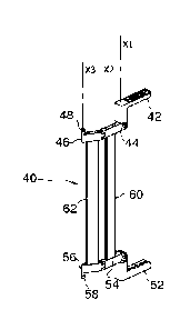
The mechanism 40 (fig. 4) comprises a pair of first arms 44, 54 hinged to
the compartment V around a vertical axis X1 by means of two optional, e.g.
angular, brackets 42, 52. The brackets 42, 52 allow the fine adjustment of the
axes X 1 , X2 inside the compartment V.
Preferably, to simplify the kinematics and the construction, the arms 46,
56 and the arms 44, 54 are parallel to each other and straight.
A second pair of parallel arms 46, 56 is hinged, respectively, to the first
arms 44, 54 around a vertical axis X2, parallel to X 1.
At the end of arms 46, 56 is mounted a wheel 48, 58 with a pivoting axis
X3 parallel to X1 and X2. The wheel 48, 58 can slide inside a complementary
guide 70 mounted on the inner side of the leaf 24 (Fig. 6); therefore, the
leaf 24
can be moved relatively to the mechanism 40 without breaking away.
To give greater rigidity to the mechanism 40, preferably the arms 44, 54
are connected by a bar 60, and/or the arms 46, 56 are connected by a bar 62.
For example. the arms 44, 54 and the arms 46, 56 may have on the side facing
the other arm a groove or cavity in which to Insert the end of the bar.
OPERATION
To move the leaf 24 and discover the compartment V, it is enough to just
pull the leaf 24 towards the outside of the furniture item 10. The leaf 24,
supported by the bracket 32 and the mechanism 40, moves away from the
furniture item 10, arranging itself more outside than the closed leaf 22. One
can
then push the leaf 24 to overlap it to the leaf 22.
At rest, with the leaf 24 closed (fig. 1), the mechanism 40 is configured
approximately as in Fig. 7, with the arms 44, 46, 54, 56 turned and directed
towards the panel 12 (FIG. 7).
6
Date Recue/Date Received 2022-02-07
The detachment of the leaf 24 from the furniture item 10 makes the arms
44, 46, 54, 56 slightly rotate toward the opposite panel 14.
Even during the horizontal sliding of leaf 24 towards and above the leaf
22, the arms 44, 46, 54, 56 rotate slightly toward the leaf closed 22 (to the
left
.. clockwise in Fig. 7 and 8) about the axis X 1 .
At the end of the stroke of horizontal sliding, the boundary of guide 70
abuts on the wheel 48, 58. Then the rotation of the arms 46, 56 about the axis
X1 and the rotation with respect to the arms 44, 54 about the axis X2
increases
a lot. Eventually, the arms 44, 54 are approximately orthogonal to the plane
of
.. the leaves 22, 24 (or, which is the same, to the back-panel 28) and the
arms 46,
56 are substantially orthogonal to the arms 44, 54 (Fig. 8).
The arms 44, 54 and the arms 46, 56 form at this point an L-shaped
support, the outer segment of which is parallel to the plane of the leaves 22,
24
(and parallel to the sliding direction of the leaves 22, 24). The articulation
with
respect to axis X2 between the arms 44, 54 and the arms 46, 56 allows the
mechanism 40 to deform and dynamically follow the movement of the leaf 24. In
particular, the rotation of the arms 46, 56 with respect to the arms 44, 54
varies
the position of the roller 48, 58 when the leaf 24 moves: the wheel 48, 58 can
therefore assume two different positions relative to the open/closed position
of
the leaf 24. Not only one gains length in the stop limit of the open the leaf
24 (the
arms 46, 56 may have any length), but the relative displacement (for e.g. the
rotation) between the arms 46, 56 and the arms 44, 54 eliminates the design
limitations for the length of the outer segment of the said L, because such
segment (here the arms 46, 56) moves along with the leaf 24. In fact, with the
rigid L-shaped arm of the prior art the support point is fixed relatively to
the
sliding direction of the leaves and does not go over the opening of
compartment
V, for which the end-of-travel stop is inherently determined.
With the arms 46, 56 also moves the wheel 58, 48 (i.e. the point of support
for the leaf 24). Also, note that the rotation of the arms 46, 56 allows said
point
of support not only to bypass the central edge of compartment V but also to
overlap the other closed leaf 22 (see 10 Fig. 9). Thus the stop limit of leaf
24
widens and/or moves towards the leaf 22, thereby allowing to uncover more the
compartment V.
7
Date Recue/Date Received 2022-02-07
The mechanism has other advantages. E.g. it has increased smoothness,
because the arms 44, 46, 53, 56 rotate on and are hinged with pins having
relatively small diameter, so the friction that these develop during their
rotation
is proportionally negligible compared to the length of the levers.
It has higher rigidity, due to the fact that there are no relative plays as in
the pinion-rack coupling of the prior art, and to the fact that torsion bars
can be
used (see. E.g. the bars 60, 62) with very robust section.
Possible variants compared to those already described are e.g.:
= the number and form of the leaves;
= the use of upper carriages in the guides 34 to move or support the leaves
is optional but advantageous. Although the mechanism 40 alone may be able to
hold the leaf, in most applications it can only ensure that the leaf 24
remains
vertically parallel to the structure of the furniture item 10, or keeps
aligned
vertically the top and bottom of the leaf 24 by avoiding asymmetries and jams
in
the carriages 30, 32, especially when the leaf 24 is guided by an upper
carriage
and a lower one;
= the use of a pair of arms 46, 56 and arms 44, 54 is optional, which
however improves the rigidity and stability of the support. It could suffice
to have
a pair of arms 46, 56 or arms 44, 54;
= the use of a pair of arms hinged to each other is optional. It could suffice
e.g. to have an L-shaped arm with the end hinged to the compartment. However
to move the abovementioned support point for the leaf one may also implement
other systems, e.g. hinged arms to the compartment around also or only to one
or more axes orthogonal to the plane of the leaf (that is, perpendicular to
the
back-panel 28), electric actuators or drivers, o articulated parallelograms.
***
8
Date Recue/Date Received 2022-02-07