Note: Descriptions are shown in the official language in which they were submitted.
1
ONCE-THROUGH VERTICAL TUBED SUPERCRITICAL
EVAPORATOR COIL FOR AN HRSG
[0001] BACKGROUND OF THE INVENTION
[0002] Natural gas and fuel oil serve as the energy source for much
of the
currently generated electricity. To this end, the gas or fuel oil undergoes
combustion
in a turbine which powers an electrical generator. The products of combustion
leave
the turbine as an exhaust gas quite high in temperature so that the exhaust
gas
represents an energy source in itself. This energy is captured in a heat
recovery steam
generator ("HRSG") that produces superheated steam that powers another
electrical
generator.
[0003] Generally, an HRSG comprises a casing having an inlet and an outlet
and
a succession of heat exchangers¨that can include a superheater, an evaporator,
and
an economizer arranged in that order within the casing between the inlet and
outlet.
[0004] Such heat exchangers for an HRSG can have multiple banks of
coils, the
last of which in the direction of the gas flow can be a feedwater heater. The
feedwater
heater receives condensate that is derived from low-pressure steam discharged
by the
steam turbine, and elevates the temperature of the water. Then the warmer
water from
the feedwater heater flows for example into one or more economizers, boiler
feed
pumps or evaporators, which convert it into saturated steam. That saturated
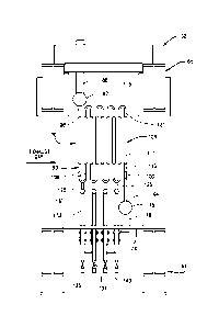
steam
flows on to a superheater which converts it into superheated steam. From such
a
superheater, the superheated steam can flow to the steam turbine.
[0005] Generally, in the above-discussed process, most HRSGs produce
superheated steam at three pressure levels ¨ low pressure (LP), intermediate
pressure
(IP) and high pressure (HP). An HRSG can thus have one or more superheaters
and
also can have what are termed an LP Evaporator, an HP Economizer, and an IP
Economizer.
Date Recue/Date Received 2020-10-28
2
[0006] An overall illustration of a system which features an HRSG using a
natural
circulation system appears in U.S. Patent No. 6,508,206 B1 (hereafter "'206
Patent").
Fig. 4 of the '206 Patent illustrates an arrangement with a superheater 18
located at
the farthest position upstream. Downstream from the superheater 16 in the
internal
HRSG flow path is at least one evaporator 18 which has in fluid flow
connection
therewith a steam drum shown located atop of the evaporator. That steam drum
is
located outside of the HRSG internal exhaust gas flow path. The HRSG in the
'206
Patent also has a feedwater heater 20.
[0007] The superheated steam produced by an HRSG has typically been
below
the critical point pressure of steam. Industry trends to build power plants of
larger
scale and of greater efficiency have evolved into a need for such plants to
operate
above, or just below, the critical pressure of water.
[0008] In a natural circulation HRSG, water is first evaporated into
saturated
steam. This takes place in the high pressure (HP) evaporator coil and drum
combination, which is simply referred to herein as "HP evaporator section"
(HPEVAP). In such an HP evaporator coil and drum combination, the evaporator
coil
is located within the internal exhaust flow path of the HRSG, while the drum
is located
exterior to the internal exhaust flow path of the HRSG, with the HP evaporator
coil
and drum being in fluid flow connection with one another. In the HPEVAP, the
density difference of steam and water at saturation conditions is the driving
force to
cause water and/or steam to circulate from a steam drum through downcomer
pipes
to the HPEVAP coil tubes, and through risers back to the steam drum. This
circulation
of saturated water in the HPEVAP is what distinguishes a natural circulation
HRSG
from other types of HRSGs.
[0009] Another type of HRSG is a system that uses a once-through
steam
generator, commonly referred to in the art as an "OTSG". In an OTSG, the
working
fluid does not recirculate through the heating surface as with a natural
circulation
HRSG system. Rather, with an OTSG the working fluid makes one pass through
each
individual parallel HPEVAP conduit and then exits the OTSG. U.S. Patent No.
6,019,070 to Duffy ("Duffy '070' Patent") discloses an HRSG having an OTSG
with
Date Recue/Date Received 2020-10-28
3
what are designated therein as circuit assemblies. Those circuit assemblies in
the
Duffy '070 Patent each comprises a serpentine shaped heat exchange tube with
U-bend shaped portions and vertically oriented linear portions, positioned
within the
HRSG internal gas flow path.
[0010] U.S. Patent No. 6,189,491 to Wittchow, et al. ("Wittchow '491
Patent")
also discloses an HRSG having an OTSG with vertically disposed steam-generator
tubes within the HRSG gas flow path. U.S. Patent No. 8,959,917 to Berndt, et
al.
("Berndt '917 Patent") discloses an HRSG that uses an OTSG, while U.S. Patent
Application Zhang having Pub. No. US 2013/0180228 Al, discloses an HRSG with
a supercritical evaporator arrangement ("Zhang '228 Applic.").
[0011] Fig. 1 of the present application shows an overall layout of a
system that
illustrates use of an HRSG similar to that shown in Fig. 3 of the '206 Patent.
Fig. 1
of the present application discloses a gas turbine G that discharges hot
exhaust gases
into an "HRSG", which extracts heat from the gases to produce steam to power a
steam turbine S. The gas turbine G and steam turbine S power the generators E
that
are capable of producing electrical energy. The steam turbine S discharges
steam at
a low temperature and pressure into a condenser CN, where it is condensed into
liquid
water. The condenser CN is in flow connection with a condensate pump CP that
directs the water back to the HRSG as feedwater.
[0012] Generally, the heat exchangers comprise coils that have a
multitude of
tubes that usually are oriented vertically and arranged one after the other
transversely across the interior of the casing. The coils are also arranged in
rows
located one after the other in the direction of the hot gas flow depicted by
the
Date Recue/Date Received 2020-10-28
CA 02964166 2017-04-07
WO 2016/057911
PCT/US2015/054927
4
arrows in Figs. 2-7 of the present application. The tubes contain water in
whatever
phase its coils are designed to accommodate. The length of the tubes can be as
great as about 90' tall.
SUMMARY OF DISCLOSURES
10013] As discussed above, in order to maximize cycle efficiency, an HRSG
generally contains multiple pressure levels of superheated steam generation
and
steam reheat. The current invention will allow the operating pressure range to
be
increased to include steam production at supercritical pressures. Since only
one
pressure system (for a given working fluid), and nominally the high pressure
(IIP)
system, can run at supercritical pressure, it is desirable to maintain natural
circulation for the other pressure levels, typically the intermediate pressure
(IP)
and low pressure (LP) systems. There can be other pressure systems and
nomenclature. This summary does not limit the type of HRSG that can be used.
[0014] At pressures approaching the critical point of water, the density
difference of water and steam at saturation conditions is much less than it is
at
lower pressures. Under such conditions, the hydrodynamics that drive the flow
in
a natural circulation evaporator are diminished to the point where another
method
is required to ultimately generate flow for the plant generation needs. In
this case,
it is practical to design and operate the HPEVAP as a once through steam
generator (OTSG) in which, as noted, the working fluid does not recirculate
through the heating surface but rather makes one pass through each individual
parallel HPEVAP tube conduit and then exits the HPEVAP section. The OTSG as
shown in Fig. 2 replaces the typical HPEVAP in a natural circulation HRSG.
Though OTSG's are known in the HRSG art, there is a need for the production of
sub-critical and supercritical steam by means employed in using an OTSG to
handle the operating conditions in a stable and mechanically acceptable
design.
The stratification of two-phase flows, critical heat fluxes, and instability
are major
concerns for designers of OTSGs. In supercritical conditions the working fluid
exists as a single phase fluid and is sensibly heated as it passes through the
parallel
circuits of the I IPEVAP.
CA 02964166 2017-04-07
WO 2016/057911
PCT/US2015/054927
[0015] In the present
disclosures, the OTSG is configured to comprise a group
of individual serpentine tubes having vertical tube sections, and bends toward
the
top and bottom that are in flow connection with the vertical tube sections.
Water
can be introduced into the inlet of the OTSG group of tubes from the exit of
the HP
5 Economizer via pressure from the HP Feedwater Pump. The water can then be
heated as it moves through the serpentine tubes in the OTSG coil, absorbing
heat
from the exhaust gas. At pressures slightly lower than the critical point the
fluid
exits as two phase or slightly superheated steam. At pressures at or above the
critical point, the fluid exits the OTSG having properties consistent with the
temperature. The OTSG operates under a high mass flux. As with other HRSGs,
the supercritical water/steam fluid exiting the evaporator coil can be heated
further
in coil sections upstream in the gas path, absorbing heat from even higher
temperature gas and increasing the temperature further to maximize the steam
cycle efficiency.
[0016] Accommodation of pressure differences that may exist between the
individual conduits that contain serpentine tubes, is provided by an inter-
association among those conduits to assist in balancing the pressure. Such
equalization promotes pressure stability among the tube circuits. The
configuration and location of the inter-association conduits utilize natural
forces to
aid in separating liquid from steam in the process, to promote two phase
separation
below the lower U-bends of the individual serpentine conduit sections. This
assists
in directing water into the equalization conduits, which promotes flow
stability.
More particularly, the disclosure preferably provides headers interconnected
among the individual conduits. The headers are preferably positioned beneath
the
bottom of the lower U-bends of the serpentine tubes transverse to the internal
exhaust gas flow. Further, the disclosure preferably includes a flow
restriction
device in flow connection with individual serpentine tubes positioned to
improve
flow distribution and flow stability, and preferably located toward the inlet
of the
serpentine tube. Moreover, the disclosure preferably provides drainage from
the
serpentine tube.
CA 02964166 2017-04-07
WO 2016/057911
PCT/US2015/054927
6
BRIEF DESCRIPTION OF DRAWINGS
[0017] Fig. 1 is a general schematic of a combined cycle power system
having
an HRSG, that can use the present invention;
[0018] Fig. 2 is a sectional view of an embodiment with an HRSG, and
illustrating a once-through vertical tubed supercritical evaporator coil;
10019] Fig. 3 is a sectional view of a first embodiment of the invention
showing part of the floor and roof of an HRSG, shown in a representative scale
of
height to width;
[0020] Fig. 4 is the preferred embodiment of the invention, showing an
inlet at
the bottom and an odd number of tube rows;
10021] Fig. 5 is a plan view of a preferred first embodiment of the
invention in
a staggered tube pitch arrangement, with an oblong bubble (123) toward the
left
end indicating the ends of one row of vertical sections of a group of
individual
conduits tube sections; The diagram beneath the drawing indicates that a
darkened
circular area represents upward flow through a vertical tube section 108 of an
individual conduit, while an "x" illustrates downward flow through an adjacent
vertical tube section 108, in alternating fashion;
[0022] Fig. 6 is a plan view of an alternate embodiment of the invention
showing an in-line tube pitch arrangement for the individual conduits, with an
oblong bubble (123) toward the left end indicating the ends of one row of
vertical
sections of a group of individual conduits tube sections; as with Fig. 5; the
diagram
beneath the drawing indicates that a darkened circular area represents upward
flow
through a vertical tube section 108' of an individual conduit 90', while an
"x"
illustrates downward flow through an adjacent vertical tube section 108', in
alternating fashion;
[0023] Fig. 7 is an embodiment of the invention wherein the individual
intermediate conduits incorporate an expansion loop to address differential
tube
expansion;
[0024] Fig. 8 is an embodiment of the invention showing an alternate
inlet
location at the top and an even number of tube rows;
CA 02964166 2017-04-07
WO 2016/057911
PCT/US2015/054927
7
[0025] Fig. 9 is an
alternate embodiment of the invention showing a mixture of
counter current flow and co-current flow, with an inlet header towards the
bottom;
and
10026] Fig. 10 is an
alternate embodiment of the invention showing a mixture
of counter current flow and co-current flow, with an inlet header towards the
top.
DETAILED DESCRIPTION OF EMBODIMENTS
[0027] The following
detailed description illustrates the claimed invention by
way of example and not by way of limitation. The description clearly enables
one
skilled in the art to make and use the disclosure, describes several
embodiments,
1 0 adaptations,
variations, alternatives, and uses of the disclosure, including what is
presently believed to be the best mode of carrying out the claimed invention.
Additionally, it is to be understood that the disclosure is not limited in its
application to the details of construction and the arrangements of components
set
forth in the following description or illustrated in the drawings. The
disclosure is
capable of other embodiments and of being practiced or being carried out in
various ways. Also, it is to be understood that the phraseology and
terminology
used herein is for the purpose of description and should not be regarded as
limiting.
[0028] For the
following description, we will refer to the supercritical
water/steam mixture and the sub-critical water/steam mixture as "fluid". This
should not infer that the behavior of sub-critical water and steam are the
same as
supercritical water/steam.
[0029] Referring to
Fig 2, an HRSG 20 has a casing 23 within which are heat
exchangers. Hot exhaust gases, such as discharged from a gas turbine (e.g.,
turbine
G of Fig. 1), enter the casing 23 and pass through a duct having an inlet 25
and an
outlet 27, such as indicated by arrows in Figures 1 and 2. During such
process,
that gas passes through heat exchangers.
[0030] The HRSG
casing 23 has a floor 30, a roof 32, and sidewalls that
extend upwardly from the floor 30 to the roof 32. The heat exchangers are
positioned within the casing 23. The floor 30 and roof 32 extend between the
CA 02964166 2017-04-07
WO 2016/057911
PCT/US2015/054927
8
sidewalls so that the floor 30, sidevvalls and roof 32 help to form the
internal duct
of the HRSG casing 23, through which the exhaust gas passes.
[0031] Fig. 2 shows an HRSG casing with an exemplary sequential
arrangement of heat exchangers. In Fig. 2, in a longitudinal direction from
left to
right, in the direction of the arrow showing exhaust gas flow, are a first
reheater
36, followed by a first high pressure (HP) superheater 39, then downstream
therefrom a second HP superheater 42 followed by a second reheater 44.
110032] In the interest of minimizing the disruption to a "typical"
horizontal
gas flow, the disclosed vertical tube once-through HP evaporator (OTSG) 47 is
shown in Fig. 2 in a preferred position. As such, it replaces a natural
circulation
HPEVAP in an HRSG. For maintaining the balance of the HRSG as normally
supplied, a horizontal gas path is preferable.
10033] The OTSG 47 comprises a large coil 52, shown in Figure 3. Coil 52
comprises individual serpentine tubes assembled into a module of convenient
size
for transportation, and will be further described. Downstream from the OTSG 47
can be a high pressure (TIP) economizer system 56, followed downstream by an
intemiediate pressure (IP) system 59, which can be then followed by a low
pressure (LP) system 61. Downstream therefrom can be a feedwater heater system
63 (e.g., such as discussed and disclosed in the '206 Patent).
[0034] The coil 52 is supported from its roof structure 42 hanging in a
steel
frame, shown partially in Fig. 3 as the roof beams 65 and floor beams 67. The
exhaust gas is contained inside the steel frame by an insulated casing and
liner
system typically found in HRSG' s and partially shown in Figure 2 as the roof
32
and floor 30.
10035] Turning now from the Fig. 2 description to a more detailed
discussion
of the OTSG 47 and its coil 52, the coil 52 comprises a plurality of
individual heat
exchange conduits illustrated as tubes 90. Fig. 3 shows a sub-group 70 of
tubes 90,
with the number of individual tube conduits reduced for purposes of
illustration.
Fig. 4 shows an even more detailed elevation view of a subgroup 70.
10036] Referring to Fig. 4, in general, the OTSG 47 has an inlet header 75,
which can be a pipe, that can receive fluid from an inlet conduit 78 that is
CA 02964166 2017-04-07
WO 2016/057911
PCT/US2015/054927
9
connected to the outlet of the HP Economizer 56 (depicted in Fig. 2). The OTSG
47 also has an outlet header 82 that is in fluid flow connection with an
outlet
conduit 86. Conduit 86 can lead to fluid flow connection with the inlet 87 of
an
external separator 88, the outlet 89 of which can lead to flow connection with
the
inlet of the HP Superheater 44 (depicted in Fig. 2).
[0037] Located between the inlet header 75 and outlet header 82 are a
group
of individual heat exchange conduits 90. The elevation view of Fig. 4 shows
one
such conduit 90. The top plan view of Fig. 5 shows that the conduit sub-group
70
comprises a plurality of such individual conduits 90 that are shown in
elevation in
Fig. 4.
[0038] Each individual conduit 90 can be a tube that has an inlet end 94
and
an outlet end 98. The inlet header 75 and outlet header 82 are preferably
cylindrical bodies arranged normal to the exhaust gas flow, with openings
along
their lengths to which the inlet ends 94 and outlet ends 98 of tubes 90 are
respectively secured, such as by welding.
[0039] As shown in Fig. 4, from the inlet conduit end 94, the conduit 90
can
preferably comprise a flow restriction device 100 through which fluid flows.
The
pressure drop associated with the flow restriction device 100 improves flow
distribution and flow stability. From flow restriction device 100, the conduit
90
generally extends into a serpentine tube section 104 (Figs. 4 and 5).
Serpentine
tube section 104 generally comprises a series of vertical tube sections 108,
which
comprise a middle portion 109. As known in the art, those vertical sections
108
can comprise a portion 111 having heat exchange fins (which portions 111 are
shown enlarged in Fig. 4), and portion 113 which have no fins. The finned
portion
111 is illustrated as overlapping the middle portion 109.
[0040] The conduits 90 also have a series of non-linear sections which
are
curved or bent, such as illustrated as a plurality of upper U-bend sections
115 and
lower U-bend sections 120. The first of the vertical sections 108 of conduit
90 is
designated 121 in Fig. 4. The flow restriction device 100 is incorporated into
the
flow path of the first sections 121, preferably before flow passes into the
middle
portion 109 of section 121.
CA 02964166 2017-04-07
WO 2016/057911
PCT/US2015/054927
[0041] Thus, in the
preferred embodiment, flow within an individual conduit
90 comprises upward flow through a vertical tube section 108 to an upper U-
bend
section 115, and then subsequent downward flow through an adjacent vertical
tube
section 108 to a lower U-bend section 120. At the last of the series of
vertical tube
5 sections 108, fluid flows upwardly through conduit outlet end 98 into
outlet header
82. Thus the flow through a conduit 90 is a continuing circuit of alternating
upward and downward paths until flow through outlet end 98 reaches the outlet
header 82.
[0042] As seen in the
plan view of Fig. 5, in the subgroup 70 a number of
10 individual conduits 90 are arranged in parallel in general alignment
with the
internal longitudinal exhaust gas flow path. Vertical tube sections 108 are
aligned
in a transverse plane that is generally perpendicular to the longitudinal
exhaust
flow path, to make up "rows" 123 of tube sections 108. Rows 123 are thus
arranged nofinal to the path of the hot exhaust gas. Fig. 5 illustrates the
direction
of upward fluid flow and downward flow through an exemplary conduit 90 located
at the bottom of Fig. 5. As noted in the description of Fig. 5, a darkened
circular
area designates upward flow through a vertical tube section 108, while an "x"
illustrates downward fluid flow through a tube section 108.
[0043] In the Fig. 5
preferred embodiment, the vertical tube sections 108
illustrated in Fig. 4 are arranged in a staggered fashion, where each tube
section
108 in the tube row 123 is positioned at the midpoint of the transverse
spacing of
the upstream and/or downstream tube row. The tube
sections 108 are thus
staggered in a longitudinal direction in the exhaust flow path in an alternate
offset
pattern. In this arrangement a vertical section longitudinally downstream from
an
adjacent vertical section is longitudinally offset therefrom in an alternating
pattern
so that the vertical sections are not in longitudinal alignment In the
particular
embodiment of Fig. 5, a first group of the vertical sections 108 are in
longitudinal
alignment with one another, and a second group of the vertical sections 108,
are in
longitudinal alignment with one another, so that the first and second groups
are
themselves offset relative to each other longitudinally. Such offset and
staggered
arrangement is known in the art as "staggered pitch."
CA 02964166 2017-04-07
WO 2016/057911
PCT/US2015/054927
11
[0044] Figure 6 shows an alternate embodiment of the serpentine
arrangement, wherein the vertical tube sections 108' are arranged in an in-
line
pitch, so that the tube sections 108', upper IT-bends 115' and lower U-bends
120'
in each individual conduit 90' are longitudinally aligned from front to rear
of each
conduit 90'. Such alignment is known in the art as "in-line pitch."
[0045] Referring to Fig. 4, the flow restriction device 100 can be in
the nature
of an orifice or constricted tube. The orifice is sized based upon the
required
pressure drop and flow rates. A device 100 is preferably placed in the first
tube
section 121 section of the first tube row 123 downstream of the inlet header
75 as
shown in Fig. 4. The location of the flow restriction device 100 is preferably
between the inlet header 75 and the finned portion 111 of the first tube
section 121.
The pressure drop associated with the flow restriction device improves flow
distribution and flow stability.
[0046] Now attention is directed toward an arrangement for equalization
among the individual conduits 90. Toward the bottom of each lower U-bend
section 120 is an intermediate equalization conduit 125. Inteimediate conduit
125
can be a relatively short piece of pipe or tube, which has its upper inlet end
connected toward the bottom of U-bend section 120, preferably in the middle
thereof. Intermediate conduit 125 allows fluid flow from the bottom center of
each
lower U-bend 120 to flow into an equalization conduit in the foim of a header
130.
Each equalization header 130 is preferably a cylindrical pipe oriented normal
to the
exhaust gas flow of the HRSG, and spans the width of one tube row 123 within
one
coil 52. The outlet ends of intermediate conduits 125 are connected to the
header
equalization conduits 130 preferably toward the top thereof. Preferably the
connection of the outlet end of inteimediate conduit 125 to the header conduit
130
is generally directly beneath the connection of the inlet end of intermediate
conduit
125 to its respective lower U-bend 120.
[0047] As shown In Figure 4, each equalization header 130 is connected
at its
underside to a drain 133, such as a pipe, to be in fluid flow connection
therewith.
The drain pipes 133 extend through the casing floor 30. A bellows expansion
joint
136 is connected with drain 133 to accommodate tube expansion during
operation,
CA 02964166 2017-04-07
WO 2016/057911
PCT/US2015/054927
12
while sealing the exhaust gas inside the floor 30. The drain pipes 133 can be
open
and shut as by valves 134, such as by the illustrated gate valves 134, ball
valves, or
other valves known in the art. The valves 134 can be operated so that the
drain
pipes 133 can carry fluid to a disposal point during times when the OTSG coil
52
may need to be emptied of fluid.
[0048] Drain bypass conduits 140, which can be pipes or tubes, connect
desired adjacent drains 133. Bypasses 140 allow a relatively small amount of
flow
to circulate between the pair of drain pipes 133 with which the bypasses 140
are
connected. The movement of fluid through the bypasses 140 is stimulated by
fluid
movement within the drain pipes 133 to thus reduce stagnation of fluid within
the
separate drain pipes 133, and create a cooling effect on the drain pipes 133.
Such
cooling can be beneficial for situations in which process conditions and the
metallurgy of the drain pipes 133 require that they be cooled during
operation.
[0049] System hydrodynamics and differing heat absorption of different
individual conduits 90 can create destabilization and pressure difference
between
individual conduits 90. Such a pressure difference causes flow through the
equalization intermediate conduits 125 and equalization headers 130 to occur
to
balance those pressure differences. Such pressure balancing has a stabilizing
effect
on the flow through the conduits 90.
[0050] As the fluid flows downwardly through vertical tube sections 108
into
each lower U-bend section 120, the fluid is subject to the forces of gravity
and the
centrifugal force of the fluid as it turns in the lower U-bend section 120.
Water,
being of higher density than steam, will be forced to the interior surface of
the
extrados of the U-bend section 120 by the centrifugal and gravitational
forces.
Particularly in the case of two-phase flow, it is desirable to redistribute
only water
flow through the equalization headers 130. The high mass flux of the fluid
through
each tube row 123 plus the forces on the higher density fluid in the lower U-
bend
sections 120 ensures that only water is present in the equalization
intermediate
conduit 125 and equalization header 130 during subcritical operation.
100511 The interior diameter of pipe forming the individual conduits 90 are
a
function of the specific design details and can for example be about .5" in.
to
CA 02964166 2017-04-07
WO 2016/057911
PCT/US2015/054927
13
about 2". The shape of the arc of the bend in U-bends 120 is preferably of a
generally semi-circular shape. The bend centerline radius of a U-bend 120 can
be,
for example, about 1.5 to about 3.0 centerline conduit diameters. The
thickness of
the wall of the individual conduits 90 can be based upon material type,
diameter,
operating temperatures and pressures.
[0052] The equalization intermediate conduits 125 are preferably pipe
having
nominal diameter in the range of about 0.25" to about 1.0". The inside
diameter of
the equalization conduit conduits 125 is preferably smaller than the inside
diameter
of the individual conduits 90. The smaller inside diameter of the equalization
intemiediate conduits 125 relative to the inside diameter of its respective
individual
tube facilitates only a relatively small amount of flow through the
intermediate
equalization conduit as compared to the amount of flow through the lower U-
bend
sections 120, to pressurize the equalization headers 130. In subcritical
operation
the flow through intermediate conduits 125 would include liquid water, which
promotes stability of the system. In a preferred embodiment the inside
diameter of
an equalization conduit 125 is noticeably smaller than the inside diameter of
its
respective individual conduit 90. In a preferred embodiment the ratio of the
inside
diameter of an equalization conduit 125 to the inside diameter of its
respective
individual conduit 90 is about 1/3 to about 1/2.
[0053] The drains 133 are preferably pipe having a nominal diameter of
about
1.5" to about 2". A bellows expansion joint 140 is used with drain pipe 133 to
take
up expansion during operation while sealing the exhaust gas inside the floor
30.
The drain pipes 133 carry fluid to a disposal point during times when the
tubes 90
may need to be emptied of fluid. Drain bypasses 144 connect adjacent drains
133
and allow a small amount of flow to circulate through the drain pipes 133 for
situations where process conditions and the metallurgy of the drain pipes 133
require that they be cooled during operation.
[0054] Figure 7 depicts an embodiment where each equalization
intermediate
conduit 125" is formed into an expansion loop shaped, or bowed, section 127".
It
is expected for coils of this type to have temperature variations between
adjacent
vertical tube sections 108 in the same tube row 123 due to external variations
in
CA 02964166 2017-04-07
WO 2016/057911
PCT/US2015/054927
14
heat input. Large variations in temperature can cause stress in the
connections
between individual conduits 90, intermediate conduits 125 and headers 130. The
equalization headers 130 effectively anchor the lower IT-bend sections 120 and
restrict differential growth in adjacent individual conduits 90. The looped or
bowed configuration of section 127" allows it to flex during expansion and
contraction so that each pair of vertical tube sections 108" connected
directly to
intel _________________________________________________________ mediate
conduit 125" can move independently of other adjacent vertical tube
sections 108" in their tube rows 123". In Fig. 7 the expansion loop section
127"
can comprise many configurations including for example "C", "V", '`U" or "L"
shape, and can have vertical and horizontal sections not in the same plane.
Such
configuration can allow independent growth or contraction of each vertical
tube
section 108 ¨ 108". The amount of temperature variation in adjacent conduits
90
will determine if the embodiment of Figure 7 is employed or not, depending on
thermal-mechanical analysis of the fluid flow, geometry and materials used.
The
expansion loop shaped configuration 127" flexes and bends during operation to
thus provide flexibility in adjusting to temperature variations that can exist
between different individual conduits 90", to thus reduce and avoid damage or
failures from creep stresses and fatigue stresses.
1100551 Figure 8
depicts an alternate embodiment where the inlet header 75"
is positioned toward the top of the coil 52". Fluid moves through the
serpentine
portions of the coil 52" in the same manner as heretofore described, but with
the
first row 123" starting with fluid flow in the downward direction. In the
Figure 8
embodiment the flow restriction device 100" is located below the inlet header
100", and above the middle portion 109" ' of the first vertical section 121".
100561 Preferably, the
overall serpentine fluid flow path flows counter current
to the exhaust gas. Alternatively, the configuration could be a serpentine
flow path
flowing co-current to the exhaust gas. In the case of such reversed flow, the
locations of the inlet headers 75, 75', 75" and 75" and outlet headers 82,
82', 82"
and 82" ' are switched with each other. The location of the first vertical
tube
section 121, 121', 121" or 121" ' ,rather than being to the far right or
farther away
from the HRSG inlet, would be to be the farthest upstream of the vertical tube
CA 02964166 2017-04-07
WO 2016/057911
PCT/US2015/054927
sections closer to the HRSG inlet 25. The repositioning of the inlet headers
75, 75',
75" or 75" could be above or below such corresponding repositioned first
vertical
section 121, 121', 121" or 121". There can also be mixed flow embodiments
with
both co-current and counter-current sections.
5 [0057] Alternatively, there could be a mixture of counter current
flow and co-
current flow in the same serpentine flow path. Figures 9 and 10 show two
alternative embodiments featuring such mixed flow. Such mixture can occur
regardless of the position of the inlet header being at the bottom or top of
the flow
path. Fig. 9 shows the inlet header 75¨ at the bottom of the flow path, while
Fig.
10 10 shows the inlet header 75¨ at the top of the flow path. As a general
exemplary description, the first three or four tube rows 113"" (Fig. 9) or
113' " "
(Fig. 10) can flow co-current to the internal exhaust gas flow before changing
direction through a loop back section 150¨ (Fig. 9) or 150¨ (Fig. 10),
respectively, to flow counter current to that flow path. The flow through the
15 individual conduits 90" or 90", respectively, terminates into the
outlet header
82" or 82", respectively. Benefits of this mixed flow path include more
efficient phase change in subcritical conditions in the co-current flow path,
and
then changing to counter current flow to complete the heating of fluid as
required.
[0058] The number of tube rows 123" and the relative position of the
inlet
78" and outlet 86" is a function of the exhaust gas conditions and the amount
of
heating surface needed to heat the fluid. The invention is not limited by the
number of tube rows 123 depicted in the figures, or the relative positions of
the
inlet 78 and outlet 86. The invention is not limited by the number of
individual
conduits or serpentine sections in the transverse direction, nor in the number
of
coils 52 that these serpentine tubes can foun and that are placed in the HRSG
exhaust path.
[0059] In operation, for startup and low load operation the system can
be
operated at subcritical conditions. During all modes of operation flow
entering the
inlet header 75 is subcooled so that the water inlet temperature is below the
saturation temperature. The system is designed to maintain this requirement by
employing economizer- -inlet approach temperature control. In order to avoid
CA 02964166 2017-04-07
WO 2016/057911
PCT/US2015/054927
16
gravity controlled flow regimes a minimum tube mass flux is desired. That flow
preferably is at least about 400 kg/ms2. Lower mass flux may be acceptable in
certain specific designs and/or operating modes. Flow stability during startup
and
low load conditions are particularly important, and preferably should be kept
above
about 400 kg/ms2. As noted, the inclusion of a flow restriction device and
pressure equalization headers serve to stabilize flow and reduce localized
temperature and pressure differences in the coil.
110060] For startup and low loads in subcritical operation, an HRSG with
an
OTSG, such as the OTSG 47 of Fig. 2, can be placed in a flow control mode. The
outlet steam/water mixture can be separated in an external separator such as
external separator 88 of Fig. 2, where the water can he recycled to the plant
condenser, for example, or to another point in the system, e.g., atmospheric
blowoff tank, an economizer connection, a dedicated flash tank, or other place
such
as known in the art. Once sufficient heat is available to the OTSG 47 to
produce
superheated steam, the flow control is preferably changed to be based upon
steam
outlet temperature and other parameters. Thereafter, pressure can be increased
to
supercritical operation.
[0061] Changes can be made in the above constructions without departing
from the scope of the disclosure. It is intended that all matter contained in
the
above description or shown in the accompanying drawings shall be interpreted
as
illustrative and not in a limiting sense.