Note: Descriptions are shown in the official language in which they were submitted.
CA 02964854 2017-04-18
WO 2015/061471
PCT/US2014/061797
1
INTEGRATED WIRELESS FERTILITY TRACKING SYSTEM
CROSS-REFERENCE TO RELATED APPLICATIONS
This application claims priority to U.S. Provisional Patent App. No.
61/894,098, titled
"Integrated wireless fertility tracking system" and filed on October 22, 2013,
the entire contents
of which are hereby incorporated by reference.
SUMMARY
In one embodiment, there is provided an apparatus comprising a thermometer.
The
thermometer comprises a wireless transceiver, at least one accelerometer, a
temperature sensor,
at least one processor, and at least one storage. The at least one storage has
encoded thereon
executable instructions that, when executed by the at least one processor,
cause the at least one
processor to carry out a method. The method comprises detecting, via the at
least one
accelerometer, that the thermometer has been picked up by a user and, in
response to detecting
that the thermometer has been picked up by the user, transmitting at least one
message via the
wireless transceiver to a computing device. The at least one message comprises
an instruction to
the computing device to cease outputting of an alarm.
In another embodiment, there is provided an apparatus comprising a
thermometer. The
thermometer comprises a wireless transceiver, at least one accelerometer, a
temperature sensor, a
display screen comprising a light source, at least one processor, and at least
one storage. The at
least one storage has encoded thereon executable instructions that, when
executed by the at least
one processor, cause the at least one processor to carry out a method. The
method comprises
detecting, via the at least one accelerometer, that the thermometer has been
picked up by a user
and, in response to detecting that the thermometer has been picked up by the
user, illuminating
the display screen with the light source.
In a further embodiment, there is provided an apparatus comprising a
thermometer and a
case. The thermometer comprises a first housing, a protrusion, and a
temperature sensor. The
case comprises an inner cavity disposed within the case, wherein at least a
portion of the inner
cavity comprises a shape corresponding to a shape of the protrusion of the
thermometer. The
case further comprises a switch and a disinfector, the disinfector comprising
an ultraviolet-light-
emitting circuit positioned to illuminate at least a portion of the inner
cavity with ultraviolet light
in response to a change in state of the switch. The thermometer and case are
arranged such that at
least a portion of the thermometer is insertable into the case and the switch
is positioned such
that the first housing of the thermometer contacts the switch when the portion
of the thermometer
is inserted into the case and changes state in response to the contact.
CA 02964854 2017-04-18
WO 2015/061471
PCT/US2014/061797
2
In another embodiment, there is provided an apparatus comprising a
thermometer. The
thermometer comprises a first housing, a protrusion from the first housing, a
cap located on a
distal end of the protrusion, and a temperature sensor. The cap comprises an
exterior surface and
the exterior surface comprises a conductive material. The cap is shaped such
that a first
dimension of the cap on a first axis perpendicular to a longitudinal axis of
the protrusion is less
than a second dimension of the cap on a second axis perpendicular to the
longitudinal axis.
In a further embodiment, there is provided an apparatus comprising a
thermometer. The
thermometer comprises a first housing, a protrusion from the first housing,
and a temperature
sensor. The protrusion has a consistent cross-sectional width for a majority
of a length of the
protrusion, and the consistent cross-sectional width has a value in a range of
0.10 ¨ 0.15 inches.
In another embodiment, there is provided an apparatus comprising a thermometer
and a
case. The thermometer comprises a protrusion, a cap located on a distal end of
the protrusion,
and a temperature sensor. The cap comprises an exterior surface and the
exterior surface
comprises a conductive material. The cap is shaped such that a first dimension
of the cap on a
first axis perpendicular to a first longitudinal axis of the protrusion is
less than a second
dimension of the cap on a second axis perpendicular to the first longitudinal
axis. The case
comprises a second housing having a second exterior surface and an inner
cavity disposed within
the case. At least a portion of the inner cavity comprises a shape
corresponding to a shape of the
protrusion of the thermometer. The shape of the cavity has a third dimension
on a third axis
perpendicular to a second longitudinal axis of the cavity that is less than a
fourth dimension of
the cavity on a fourth axis perpendicular to the second longitudinal axis. The
thermometer and
case are arranged such that at least a portion of the thermometer is
insertable into the case. The
first dimension is larger than the third dimension and the third dimension is
less than the fourth
dimension.
In a further embodiment, there is provided an apparatus comprising a
thermometer and a
case. The thermometer comprises a first housing having a first exterior
surface and the first
exterior surface comprises a material. The thermometer further comprises a
protrusion, a
temperature sensor, and a display screen disposed within the first housing
such that the material
covers the display screen. The case comprises a second housing having a second
exterior surface,
and an inner cavity disposed within the case. At least a portion of the inner
cavity comprises a
shape corresponding to a shape of the protrusion of the thermometer. The
thermometer and case
are arranged such that at least a portion of the thermometer is insertable
into the case. The first
exterior surface and second exterior surface are shaped such that, when the
thermometer is
inserted into the case, the first exterior surface and second exterior surface
form a unified shape.
The unified shape has a continuous form at an intersection of the thermometer
and the case.
CA 02964854 2017-04-18
WO 2015/061471
PCT/US2014/061797
3
In another embodiment, there is provided an apparatus comprising a
thermometer. The
thermometer comprises a first housing, a protrusion from the first housing
that comprises a
conductive material disposed on a distal end of the protrusion, and a
temperature sensor. The
thermometer is arranged for use as an oral thermometer in which the distal end
will be located
underneath a user's tongue. The protrusion comprises a teeth-gripping region,
the teeth-gripping
region being a section of the protrusion to be gripped by a user's teeth
during use. The teeth-
gripping region is located on the protrusion at a distance from the distal end
of the protrusion that
corresponds to a distance between front teeth and a rear region of an
underside of a tongue of an
average adult human. A center of gravity of the thermometer is located between
0.5 and 1 inches
from the teeth-gripping region of the protrusion.
In a further embodiment, there is provided an apparatus comprising a
thermometer and a
case. The thermometer comprises a first housing, a first electrical contact
disposed on an exterior
of the first housing, a protrusion, a first battery, and a temperature sensor.
The case comprises a
second housing, a second electrical contact disposed on an exterior of the
second housing, and an
inner cavity disposed within the case. At least a portion of the inner cavity
comprises a shape
corresponding to a shape of the protrusion of the thermometer. The case
further comprises a
second battery, an external port via which to receive power from an external
source, and a
charging circuit electrically connected to the external port, to the second
battery, and to the
second electrical contact. The thermometer and case are arranged such that at
least a portion of
the thermometer is insertable into the case, and the first electrical contact
and second electrical
contact are positioned such that they contact one another when the portion of
the thermometer is
inserted into the case. The charging circuit is configured to selectively
charge the first battery
and/or the second battery using power received via the external port. The
charging circuit is
configured to select at a time whether to charge the first battery and/or the
second battery based
at least in part on whether the thermometer is inserted into the case and on a
current charge of the
first battery and/or the second battery.
In another embodiment, there is provided an apparatus comprising a
thermometer. The
thermometer comprises a temperature sensor, at least one processor, and at
least one storage
having encoded thereon executable instructions that, when executed by the at
least one
processor, cause the at least one processor to carry out a method. The method
comprises,
following a start of reading of a temperature with the temperature sensor,
detecting a completion
of the reading of the temperature and, in response to detecting the
completion, providing a signal
to a user that the reading is complete, wherein providing the signal comprises
providing a haptic
and/or visual signal to the user.
CA 02964854 2017-04-18
WO 2015/061471
PCT/US2014/061797
4
BRIEF DESCRIPTION OF DRAWINGS
The accompanying drawings are not intended to be drawn to scale. In the
drawings, each
identical or nearly identical component that is illustrated in various figures
is represented by a
like numeral. For purposes of clarity, not every component may be labeled in
every drawing. In
the drawings:
Figure 1 is a sketch of an exemplary pair of a computing device and a
thermometer and
case with which some embodiments may operate;
Figures 2A, 2B, and 2C illustrate exemplary embodiments of a thermometer and
case,
and exemplary components thereof;
Figure 3A is a sketch of an example of a thermometer in accordance with some
other
designs, with which some embodiments may operate;
Figure 3B is a sketch of an example of a thermometer in accordance with some
embodiments;
Figure 4A is a sketch of an example of a thermometer probe and tip in
accordance with
some other designs, with which some embodiments may operate;
Figure 4B is a sketch of an example of a thermometer probe and tip in
accordance with
some embodiments;
Figure 5A shows steps of several example processes, with which some
embodiments may
operate; and
Figure 5B shows an example of steps that may be included in a process that may
be
implemented in some embodiments.
DETAILED DESCRIPTION
Charting oral basal body temperature (BBT) and other fertility signs is an
effective way
to determine the fertility status of human females throughout the menstrual
cycle. Many women
undertake fertility charting as an aid to conception, as a way to effectively
avoid pregnancy, as a
way to better understand their gynecological health, or as a way to identify
and characterize
fertility problems. Conventional methods rely on simple manual thermometers
with generally the
same design as fever thermometers, and paper charts.
The inventors have recognized and appreciated that, although the conventional
methods
depend on consistent use to produce dependable results, the conventional
methods suffer from
usability problems that often reduce consistent use over time. Because women
typically chart
their fertility over a period of multiple months, the usability problems
result in poor data and
poor results when the conventional methods are used.
CA 02964854 2017-04-18
WO 2015/061471
PCT/US2014/061797
Described herein are various embodiments of an Integrated Wireless Fertility
Tracking
System. Various embodiments include a fertility thermometer and processes for
collecting and
charting fertility data. Some embodiments have increased usability relative to
conventional
systems, making fertility charting easier and more effective for the user and
thereby increasing
5 user satisfaction and user compliance, which in turn increases
effectiveness of the system.
Techniques herein may, in some embodiments, be used together with techniques
and apparatuses
described in U.S. Patent Application Serial No. 13/696,438, filed on November
6, 2012, and
titled "System for tracking female fertility" ("the '438 application"), and/or
in any of the
applications to which the '438 application claims priority, including U.S.
Patent Applications
Serial Nos. 61/332,701, filed May 7,2010, 61/350,084, filed June 1,2010, and
61/354,182, filed
June 11, 2010, and International Patent Application Serial No.
PCT/US2011/027196, filed
March 4, 2011 ("the Priority Applications"). The '438 application and all of
the Priority
Applications are incorporated herein by reference in their entireties and at
least for their
discussion of techniques and apparatuses for tracking female fertility.
One embodiment of an Integrated Wireless Fertility Tracking System is
illustrated in
Figure 1. As shown in Figure 1, this embodiment includes an oral fertility
device (1) to collect
oral temperature readings from a user, which may be a female, including a
human female. The
oral fertility device (1) is arranged to wirelessly transmit the oral
temperature readings ¨ in some
cases along with the time and date of each reading ¨ to another device. In the
embodiment of
Figure 1, this other device is an Internet-enabled device (2), which may be
any suitable
computing device, for example a smartphone. The device (2) may be configured
to execute a
software application (48). The software application (48) may carry out various
functions relating
to fertility data for the user. Such fertility data may include oral
temperature readings received
from the oral fertility device (1). The software application (48) may, for
example, record/store
fertility data for the user in one or more storages of the device (2), display
the fertility data via a
user interface of the device (2), analyze/process the fertility data in some
manner, and share the
fertility data by transmitting the fertility data via one or more wired and/or
wireless computer
networks to one or more other devices.
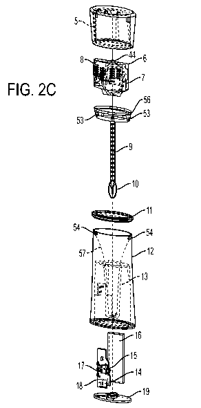
Figures 2A-2C illustrate additional details of one embodiment of the oral
fertility device
(1) of Figure 1. As shown in Figures 2A-2C, the fertility device is composed
of an integrated oral
thermometer (3) and case (4). The thermometer (3) includes a thermometer head
casing (5), a
battery (7), circuit board (6) containing a microprocessor, temperature
circuit, accelerometer,
wireless transceiver, and screen driver, a flexible screen (8), a probe (9)
and probe tip (10). The
probe tip (10) may be formed of a conductive material, which may be a metal.
The thermometer
case (4) includes a trim ring (11), molded case body (12) that includes an
internal guide (13) for
CA 02964854 2017-04-18
WO 2015/061471
PCT/US2014/061797
6
the probe (9) of the thermometer (3), UV disinfecting light (14), position-
sensing switch (15),
battery (16) and control circuit (17) that manages the charge of the battery
and activates the UV
disinfecting light (14) when the thermometer is placed back in the base, and
charging port (18).
The case (4) also includes a base plate (19).
Embodiments may include/implement one or more, in any combination, of the
following
functionalities.
First Functionality
With reference to Figures 2A-2C, the thermometer (3) and case (4), when fitted
together
such that the probe (9) and probe tip (10) are inside the body (12) and
internal guide (13), may
form an integrated shape that is not suggestive of a thermometer. Additionally
or alternatively,
the screen (8) may be positioned on the thermometer (3) such that the screen
(8) is concealed
behind a translucent surface material of the head casing (5), making the
screen (8) difficult to
see, or invisible, when the screen (8) is not illuminated. These two features,
alone or in
combination, may prevent the device (1) from being easily identified as a
fertility tracking device
or as a medical device.
This may be advantageous for some women who are charting their fertility to
achieve or
avoid pregnancy. Thermometers using other designs are easily identifiable as
such and therefore
easily communicate to others that a user may be sick, or possibly that the
user is charting
fertility. As family planning may be a sensitive topic for some users, home
users of
thermometers having other designs may go to lengths to place their
thermometers out of sight
after use. Similarly, for women who take thermometers having other designs
with them to
various locations (their partner's house, while traveling, etc.), these other
thermometers may also
communicate sickness and/or fertility tracking if seen being carried or in a
purse and such
women take steps to conceal them.
Embodiments that incorporate this shape may remove or mitigate this concern by
concealing or obscuring the nature and function of the device (1) when it is
not in operation.
Embodiments that incorporate this shape may therefore allow users to chart
fertility without
overtly communicating this fact to those around them. Some users may therefore
feel more
comfortable leaving the device on a bedside table or otherwise in the open at
home, or not feel
nervous or embarrassed traveling with the device. For those for whom fertility
tracking is a
sensitive subject, this makes the process of fertility charting easier and
more convenient for the
user. Additionally the usability of the process is improved since the
thermometer is more likely
to be close at hand instead of hidden out of sight.
CA 02964854 2017-04-18
WO 2015/061471
PCT/US2014/061797
7
In some embodiments that incorporate this shape, the device (1) may be formed
in part by
molding the thermometer head casing and case body from identical semi-
translucent material
(e.g., plastic, rubber, latex, urethane, or any another suitable material, as
embodiments are not
limited in this respect) and by modeling the thermometer and case as one
object with a unified
shape as shown in Figure 2A. By forming the device in this manner, the
transition between the
head and the case may be slight. Such a slight transition may mean that, for
example, a shape of
the exterior of the case (4) at the interface of the case (4) and the
thermometer (3) may match a
shape of the exterior of the thermometer (3). The shapes may match when there
is a continuity in
a shape that is formed when the shapes of the respective parts are positioned
adjacent to one
another. Such a continuity may be a continuity that is perceptible to a casual
observer such that
the casual observer will interpret the thermometer and case as one unified
shape. The shape of
the entire object may be very different from existing thermometers, and may be
considered to be
more similar to cosmetic products. The object therefore may not communicate to
a casual
observer that it includes a thermometer.
To hide/obscure the screen when not illuminated, the screen (8) may be
positioned on a
flexible circuit board that fits within the shape of the inside of the
thermometer head case (5).
When illuminated and in operation, the screen (8) shines through the
thermometer head material.
When it is not illuminated, the screen (8) is obscured by the thermometer head
material and
thereby invisible or obscured. This may enable the thermometer to masquerade
as some other
type of object. To power the screen (8), the screen (8) is attached via a
flexible connector to a
control circuit board (6) and battery (7), which may also be placed inside the
head case.
Second Functionality
With reference again to Figures 2A-2C, in some embodiments, the device (1) may
include an integrated Ultra-Violet disinfector within the case (4). The UV
disinfector may act to
disinfect (which may include destroying some, most, more than 90 percent of,
nearly all, or a
medically-significant amount of bacteria) the thermometer probe (9) and tip
(10) between uses,
when the probe (9) and tip (10) are inserted into the case (4). Thermometers
of other designs do
not include a disinfector, and if disinfecting is desired (as is recommended),
the thermometers
must be separately cleaned with soap and water. Embodiments that include the
UV disinfector
enable the probe and tip to be disinfected between uses. For germ-conscious
users, this may
make the device (1) easier to use and more convenient than other thermometers,
which may
increase compliance for these users.
The UV disinfector consists of a battery (16), control circuit (17), charging
port (18), UV
LED or light bulb (14), and a sensing switch (15) mounted in the thermometer
base. The control
CA 02964854 2017-04-18
WO 2015/061471
PCT/US2014/061797
8
circuit (17) may include a processor executing instructions to carry out a
process for controlling
the UV disinfector.
In some embodiments, the switch (15) may be a switch that is operated by a
user to
operate the disinfector. In other embodiments, the probe (9) and switch (15)
may be positioned
such that, when the thermometer (3) is inserted into the case (4) after use,
the probe (9) changes a
state of the switch (15) without the user needing to take a separate action to
operate the switch.
The switch (15) may be implemented in any suitable manner, as embodiments are
not limited in
this respect. In some embodiments, the switch (15) may be a position sensing
displacement
switch that is tripped by the probe tip (10) or probe base (56), an optical
position sensing switch
that registers the presence of the probe (9) or probe tip (10) inside the
probe guide (13), an
electrical sensing switch that uses electrical connections on the thermometer
head (53) to detect
that the thermometer has been replaced in the case, or any other kind of
switch.
In some embodiments, in response to detecting a change in state of the switch
(15), the
UV disinfector circuit (17) turns on the light (14) to disinfect the probe (9)
and/or probe tip (10)
for a time, then turns the light (14) off. The time may be any suitable period
of time, as
embodiments are not limited in this respect. In some embodiments, the time may
be a set interval
programmed into a storage of the UV disinfecting circuit (17).
In some embodiments, for the UV disinfecting light shine on the probe, the
probe guide
(13) includes a transparent window. This window may be molded in transparent
plastic as part of
the probe guide (13). When the thermometer (3) is placed back in the case (4)
and the
disinfecting circuit (17) activates the UV light (14), light shines through
the window in the probe
guide (13) and disinfects the probe. The window may enable the probe (9) and
tip (10) to be
disinfected while keeping the probe (9) and tip (10) physically separate from
the UV light (14)
and electronics (15-18) of the UV disinfector.
The UV disinfector battery (16) charges through a charging port (18) (which
may be any
suitable port, including a mini or micro USB) mounted in the thermometer case
(4). In
embodiments in which the charging port (18) is located on or near the bottom
of the case (4), the
base plate (19) may have an opening through which a charging cable may attach.
Third Functionality
In embodiments, as shown in Figures 2A-2C, the device (1) may charge both the
battery
(7) in the thermometer (3), which powers the control circuit, transceiver,
screen and thermometer
circuitry, and the battery (16) in the case (4), which powers the UV
disinfector, using the same
case-mounted charging port (18). This may be accomplished by adding a discrete
electrical
connection between the thermometer head (53) and the case (54).
CA 02964854 2017-04-18
WO 2015/061471
PCT/US2014/061797
9
Additionally, in some embodiments, a programmed microcontroller (17) in the
case (4)
and a programmed microcontroller (55) in the thermometer (3) may manage the
charge of the
respective batteries to route charging energy to the batteries as appropriate
to ensure both
batteries are maximally charged. This may enable the device to have a single
charging port,
which may be advantageously hidden when the device (1) is in some positions
(e.g., standing up)
to conceal the fact that the device (1) is an electronic object.
The balancing of charging of the two batteries may be accomplished by the
microcontroller (17) in the base sensing, through an electrical connection,
the current charge of
each battery. The microcontroller (17) may execute instructions and, in
accordance with a
programmed sequence of operations defined by the instructions, and known
techniques to route
charging energy first to the battery (7) in the thermometer (3) until it is
fully charged as
determined by its voltage, and then routing charging energy to the battery
(16) in the case (4)
until it is fully charged. Additionally, the microcontroller (17) in the base
may prioritize charging
the battery (7) in the thermometer (3) when the device isn't plugged in, and
therefore send it
charging energy to make sure the battery (7) in the thermometer (3) has
sufficient charge to
operate even when the battery (16) in the case (4) is fully drained.
In some embodiments, the battery (7) in the thermometer (3) may be smaller
than the
battery (16) in the case (4). For example, the battery (7) may be physically
smaller and hold a
lesser charge than the battery (16). In such embodiments, using a battery (7)
that is physically
smaller may aid in reducing a size of the thermometer (3) and/or case (4),
which may be
advantageous in some embodiments. Further, through the charge-balancing
functionality
discussed in this section, in some such embodiments the thermometer (3) may
not have a limited
battery lifespan despite having a battery (7) that is physically smaller and
holds a lesser charge.
It should be appreciated that, in some embodiments, the device (1) may include
two
charging ports, one on the thermometer (3) and one on the case (4), as
embodiments are not
limited in this respect.
Fourth Functionality
As shown in Figure 3B (and with reference to Figures 2A-2C), in some
embodiments the
oral thermometer probe (9) may not have a taper, but instead may have a
consistent cross-
sectional width between the interface (40) and the probe tip (10). Such a
consistent cross-
sectional width may be the cross-sectional width for the entirety of the probe
(9) between the
interface (40) and tip (10) or for a majority of the probe (9). For example,
in some embodiments,
the probe (9) may have a consistent cross-sectional width for more than half,
or more than two-
thirds, or more than 90 percent of the length of the probe (9) between the
interface (40) and tip
CA 02964854 2017-04-18
WO 2015/061471
PCT/US2014/061797
(10). In some embodiments, the probe (9) may have a circular shape in cross
section, and the
consistent cross-sectional width may be a diameter. In some such embodiments,
the probe (9)
may have a constant diameter of a size (e.g., in a range of 0.10 ¨ 0.15
inches, including a
diameter of 0.115 inches) that, for most humans, fits between and can be
easily grasped by the
5 user's teeth (20) for comfort while taking a temperature.
Thermometers implementing a different design, such as the one illustrated in
Figure 3A,
use a tapered probe design (21) that acts like a wedge in a user's mouth and
makes it difficult to
hold the thermometer still, as the natural motion of an inclined plane with
forces applied to its
faces is to retreat in the direction opposite to its point.
10 In
these embodiments, the probe (9), in contrast, may not have a natural
proclivity to
retreat (in a direction along a longitudinal axis of the probe (9)) from a
user's mouth when
grasped by the teeth or lips, or may have a reduced natural proclivity as
compared to other
thermometers that include the taper. Additionally, in some such embodiments,
the probe (9) may
have a diameter (22) that enables, for most humans, the probe (9) to be
conveniently grasped
between individual teeth. Gripping the probe (9) between individual teeth may
more comfortable
for most users than holding it with lips (as users often do with other
thermometers), since the
user may be able to close or mostly close her jaw (her top and bottom teeth
reaching a proximity
of 0.10 ¨ 0.15 inches in the closed position) and mouth and relax her face and
lip muscles while
taking the measurement. These features may make our system more comfortable
for the user
(which increases compliance), and reduces the likelihood of movement during
the measurement
(thus increasing accuracy of measurement).
To achieve this non-tapered shape, in some embodiments the probe (9) may be
molded
from a flexible material (e.g., rubber, silicone, plastic, or other material,
as embodiments are not
limited in this respect). In one embodiment, the lower half (23) of the probe
(9) may be more
flexible than the upper half (24). This may enable the probe (9) to be more
flexible where
flexibility may enable greater comfort for users (e.g., where the lower half
(23) may be located
under the tongue), but allow for greater rigidity between the teeth and the
thermometer head.
Rigidity on the upper half (24) may reduce a likelihood that the thermometer
head will hang
downward from the mouth at an angle that is difficult for the user to read
while the lower half
(23) is inside the user's mouth.
In one embodiment, the probe (9) may include a smaller inner diameter (while
keeping
the outer diameter of the entire probe constant) closer to the top (24) to
allow for extra rigidity
and a secure connection with the thermometer head. The probe base (25) is
large and fits into the
thermometer head (26), which may allow for a secure and strong connection
between the probe
assembly and the thermometer head.
CA 02964854 2017-04-18
WO 2015/061471
PCT/US2014/061797
11
To assemble the thermometer (3), in some embodiments, the temperature sensor
(56) is
inserted into the probe tip (10), and then the leads from the sensor (27) are
connected through the
probe (9) from the bottom to the top before the probe tip assembly is securely
fastened to the
probe. The sensor leads are then attached to the circuit board inside the
thermometer head (26).
Fifth Functionality
As shown in Figure 3B (and with reference to Figures 2A-2C), in some
embodiments, the
thermometer (3) has a center of gravity (38) of the thermometer (3) close to
the probe tip (10) to
create a low amount of torque on the user's tongue, lips and teeth while the
probe tip (10) is
inside the user's mouth and a measurement is being taken. To achieve this, the
battery, circuit
board, and wireless transmitter are located close to the base of the probe.
Furthermore, in some
embodiments, the intersecting surface (40) between the probe (9) and
thermometer head (26) is
curved to accommodate the lips. This may enable the user to place the
thermometer close to her
mouth, with her lips contacting the surface (40), further reducing the torque
the thermometer
head (25) exerts on the users lips, mouth and teeth when cantilevered out of
the mouth.
In some embodiments, the center of gravity (38) is (i) between 0.25 and 1
inches, and in
some embodiments 0.5 inches, from the location (41) at which a user will place
her teeth, and/or
(ii) between 2.2 and 3.0 inches from the probe tip (10). This is in contrast
to the thermometer
shown in Figure 3A, which may place the center of gravity between 1.5 and 2.5
inches from the
teeth (42). The thermometer of Figure 3A, by implementing such a design,
impose a torque lever
between 1.5 and 5 times greater than the torque lever that is imposed on a
user's mouth by
embodiments that place the center of gravity between 0.5 and 1 inches from the
user's teeth.
In the embodiment of Figure 3B, to locate the center of gravity close to the
teeth, various
components of the thermometer (3) are located close to the teeth (41). In some
embodiments, the
screen (8), circuit board (6), and battery (7) may be layered on top of each
other and located in
the head (26) closer to the probe base (25) than to the other side of the head
(26). This is in
contrast to the thermometer shown in Figure 3A, which places the battery (43)
at the far end of
the thermometer past the screen, thus moving the center of gravity away from
the teeth and
decreasing user comfort.
Sixth Functionality
As shown in Figures 2A-2C and 3B, in some embodiments the oral thermometer
probe
tip (10) has a shape that enables heat transfer at a rate faster than may be
achieved with tips of
other shapes. Faster heat transfer may reduce the time needed for the
thermometer (3) to take a
measurement, as compared to a thermometer having the design illustrated in
Figure 4A, and may
CA 02964854 2017-04-18
WO 2015/061471
PCT/US2014/061797
12
increase user comfort by decreasing the amount of time a user needs to hold
the thermometer in
her mouth. In other thermometers, probe tips are cylindrical with a pointed
tip (28). This both
makes the tip pointy and uncomfortable to rest against the back of the user's
"heat pocket" (29)
(e.g., an area underneath the tongue in which basal body temperature may be
read), and slows the
heat transfer from the users heat pocket to the temperature sensor inside the
tip.
As shown in Figure 4B, in some embodiments, the probe tip (10) achieves faster
heat
transfer to the temperature sensor in one or both of two ways.
First, in some embodiments, when viewed in cross-section, the probe tip (10)
may be
wider in one dimension than another. For example, a width (30) of the probe
tip (10) when
viewed from above (in "plan view") may be larger than a height (34) of the
probe tip (10) when
viewed from the side (in "side view"). The width may be, for example, between
two to three
times larger than the height. The width (30) may be the dimension of the probe
tip (10) in one
axis perpendicular to a longitudinal axis of the probe (9) and the height (34)
of the probe tip (10)
may be the dimension of the probe tip (10) in another axis perpendicular to
the longitudinal axis
of the probe (9). As shown in Figure 4B, the probe tip (10) may have a "disk"
shape in some
embodiments. Accordingly, the probe tip (10) may be flat when viewed from the
side, or flatter
in side view than a cylindrical probe tip (31) (35) of the thermometer design
shown in Figure 4A.
Therefore, the probe tip (10) may have a larger area of contact equal to 0.07
¨ 0.09 square inches
with a user's heat pocket (32) as compared with a probe tip (33) of other
thermometer designs,
which are in the range of 0.04 ¨ 0.06 square inches. This larger area of heat
transfer means the
probe tip may heat faster to the temperature of the user's heat pocket.
Second, the probe tip (10) is flatter in side view (34) than a probe tip (35)
of the
thermometer design shown in Figure 4A. This means that the distance from the
heat pocket (36)
to the temperature sensor (37) in the embodiment of Figure 4B may be shorter
than in the design
illustrated in Figure 4A. For example, the distance from the heat pocket (34)
to the sensor (37) in
the embodiment of Figure 4B may be up to 4x shorter in some embodiments than
in the
thermometer of Figure 4A. This results in faster heat transfer to the
temperature sensor and a
faster temperature measurement, which may make the thermometer more convenient
for the user.
Accordingly, in some embodiments the probe tip (10) is flat in profile and
rounded in
plan view, which may match the shape of the user's heat pocket. This makes it
more
comfortable. Also, because there may be more metal in direct contact with the
heat pocket, and a
shorter distance from the surface of the probe tip to the temperature sensor,
the thermometer of
the embodiments of Figure 4B accomplishes a faster heat transfer than with the
thermometer of
Figure 4A, which may translate into a faster and more accurate measurement.
CA 02964854 2017-04-18
WO 2015/061471
PCT/US2014/061797
13
This shape of the probe tip (10) may be achieved, in some embodiments, by
creating a
custom die and stamping the probe tips from stainless steel. The temperature
sensor may then be
potted inside the probe tip with conductive epoxy and allowed to dry before
the leads are fed
through the probe, and the tip is attached to the probe with medical-grade
adhesive. With some
manufacturing processes, stamping the tip may enable achieving a desired shape
while keeping
the wall thickness low or at a minimum, which is advantageous for fast heat
transfer.
Seventh Functionality
With reference to Figure 2C, in some embodiments, the thermometer (3) is
configured to
provide haptic and/or visual feedback to the user in response to finishing
taking a temperature
measurement. Thermometers of other designs may be silent or provide an audible
signal (e.g., a
"beep") to indicate the measurement has finished. Audible signals can be
disadvantageous in the
context of fertility charting. It is recommended that temperature be taken
early in the morning
before getting out of bed, and an audible signal can unintentionally wake up
the user's partner in
the morning. This may anger the user's partner and/or the user, and may reduce
compliance. In
some embodiments, rather than an audible feedback, the thermometer (3) may be
configured to
provide a haptic and/or visual signal. Haptic and/or visual signals may be
less likely to disturb
the partner of the user, who may be sleeping in the same bed as the user.
Though, it should be
appreciated that some embodiments may include an auditory signal. For example,
in some
embodiments, the thermometer may be configurable either to produce or not
produce one or
more of an audible signal, a haptic signal, and/or a visual signal in response
to finishing a
temperature measurement.
In embodiments that provide visual feedback, the visual feedback may be
provided in any
suitable manner. For example, in some such embodiments, the visual feedback
may be presented
via the screen (8). For example, visual feedback may be accomplished by the
circuit board (6)
and/or circuit board (17), executing instructions with a processor, detecting
completion of a
measurement and responding to the completion by displaying a graphic on the
screen (8), such
status bar, or by increasing the brightness of the screen (8).
In embodiments that provide haptic feedback, the haptic feedback may be
provided in
any suitable manner. For example, in some such embodiments, the haptic
feedback may be
accomplished with a haptic feedback chip on the circuit board (6). Such a
haptic feedback chip
may incorporate a linear resonant actuator, or may vibrate through any other
suitable hardware or
other technique. In such embodiments, the circuit board (6), executing
instructions with a
processor, may detect completion of a measurement and respond to the
completion by
controlling the haptic feedback chip to provide a haptic feedback pattern to
the user, to indicate
CA 02964854 2017-04-18
WO 2015/061471
PCT/US2014/061797
14
to the user that the measurement has finished. This enables the user to keep
her eyes closed
during the measurement and "feel" when it is finished through her teeth and
lips or fingertips.
This may allow her to remain in a more restful state during the measurement.
Eighth Functionality
With reference to Figure 2C, in some embodiments, the thermometer (3) may
include a
wireless transceiver (e.g., a Bluetooth Low Energy (BLE)) transceiver (45)
and/or an
accelerometer (46). In these embodiments, the user may set an alarm (e.g., a
wake-up alarm) on
her smartphone (2) or other wireless device. The user may then be able to turn
off the alarm,
after the alarm goes off, simply by picking up and/or pushing a button (44) on
the thermometer
(3). This may make fertility charting easier, since the user can set her alarm
on her smartphone or
other device like she is accustomed (research has shown that a high percentage
of women with
smartphones use their smartphone as their alarm clock), yet turn off her alarm
without touching
her phone. As fertility charting techniques recommend charting fertility early
in the morning,
before getting out of bed, a user of the fertility tracking system may be
woken by the alarm on a
smartphone (or other device) and, as a first action following being awoken,
pick up the
thermometer (3) to take a temperature measurement. By configuring the
thermometer (3) to
communicate to the smartphone/device turn off the alarm when the thermometer
(3) is picked up
and/or when a button is pressed, the thermometer (3) can simplify the user's
morning routine by
removing the need to separately operate the smartphone/device to turn off the
alarm.
In embodiments, this feature effectively turns the thermometer into an "off"
button for
the alarm on the smartphone (or other device). By turning the thermometer into
the alarm "off"
button (by means of an accelerometer or button) the user is able to accomplish
two steps in one:
turn off her alarm and pick up her thermometer to take her morning waking
temperature. This
feature may make fertility charting easier. The feature may also increase
compliance by turning
the thermometer into a haptic reminder to the user to take her temperature as
soon as she wakes
up and turns off her alarm, as her thermometer will already be in her hand
when she turns off her
alarm.
Embodiments may implement this feature in any suitable manner, as embodiments
are
not limited to implementing any particular process. Figure 5B illustrates one
example of a
process by which the thermometer (3) may be operated as an alarm "off" button
for another
device.
Figure 5A also illustrates other processes that may be implemented by
thermometers of
other designs. As shown in Figure 5B, processes that may be implemented in
some embodiments
may be advantageous as compared to the user workflow with current fertility
thermometers that
CA 02964854 2017-04-18
WO 2015/061471
PCT/US2014/061797
include either integrated alarms or no alarms. Integrated alarms may be
disadvantageous in that
they are operated via the user interface of the thermometer, which may have a
small screen and
buttons that may be difficult to use, and also must be set when the user is
holding the
thermometer. In embodiments, the process implemented by the thermometer (3) in
5 communication with a smartphone or other device may fit a user's current
or pre-existing
workflow. This may be because the user may traditionally have set an alarm on
her
phone/device, as discussed above, and using the thermometer (3) in connection
with that
phone/device may not be a change in routine that would qualify as
disconcerting or as a difficult
adjustment for some users.
10 As shown in Figure 5A, other processes for waking up and taking basal
body temperature
have between 10 and 12 steps (49,50,51). In contrast, processes that may be
carried out using
some embodiments (e.g., the process of Figure 5B) that incorporate this
feature have five steps.
This may increase ease of use and convenience for users, thereby increasing
compliance and
improving results.
15 With reference again to Figure 2C, in some embodiments, this
functionality may be
implemented by a processor of the circuit board (6) and/or circuit board (17)
executing
instructions stored in one or more storages. The instructions may embody a
process including
various acts.
In some embodiments, the process may include initializing communication
between the
thermometer (3) and the smartphone (or other device). The initializing of
communication may be
carried out in any suitable manner, as embodiments are not limited in this
respect. For example,
in some embodiments that implement the Bluetooth protocol, the thermometer
(3) may be
"paired" with the smartphone (or other device) using a conventional Bluetooth
pairing process.
As such pairing processes are known, they will not be discussed further
herein. In other
embodiments, however, such as embodiments that include a BLE transceiver, a
pairing process
may not be carried out during initialization. In embodiments that include an
initialization,
following initialization the thermometer (3) may communicate with the
smartphone/device.
In some embodiments, the process may also include detecting a user operation
that
signals that an alarm should be turned off. The user operation may be any
suitable operation, as
embodiments are not limited in this respect. For example, the process may
include detecting, via
a signal received from one or more accelerometers, that the user has picked up
the thermometer
(3). As another example, the process may include additionally or alternatively
detecting a change
in state of a mechanical or electrical switch on the exterior of the
thermometer head (53),
indicating that the thermometer (3) has been removed from the case (4). As a
further example,
the process may include additionally or alternatively detecting that the user
has pushed a button
CA 02964854 2017-04-18
WO 2015/061471
PCT/US2014/061797
16
on a user interface of the thermometer, or otherwise provided input that the
alarm should be
turned off. As a further example, the process may include additionally or
alternatively detecting
that the thermometer (3) has taken a temperature, such as a temperature of the
user.
The process may additionally include, in response to the user operation,
operating a
wireless transceiver (e.g., a BLE transceiver) of the thermometer (3) to
transmit or advertise one
or more messages to the smartphone or other device. The message(s) may include
any suitable
content, as embodiments are not limited in this respect. In some embodiments,
the message(s)
may indicate that a user has picked up and/or begun operating the thermometer.
In other
embodiments, the message(s) may include an indication that the user appears to
be awake. In still
other embodiments, the message(s) may include a "turn alarm off" instruction,
or other suitable
instruction, to the smartphone or other device. The "turn alarm off" message
may be any suitable
message according to any suitable protocol, as embodiments are not limited in
this respect.
Once the smartphone or other device receives the message via its own wireless
transceiver (e.g., another BLE transceiver), the message may be processed by
any suitable
software process on the smartphone/device. For example, in some embodiments,
the message
may be presented to a fertility data collection and/or charting application on
the smartphone,
which may in response communicate to an alarm application, fertility charting
application, phone
operating system, or other process to turn off the alarm.
Embodiments have been described in which an alarm is audibly, haptically,
and/or
visually output on a smartphone (or other device) and a thermometer transmits
one or more
messages to the smartphone to cease outputting of the alarm. In some
embodiments, the
thermometer (3) may also include a user interface to output an alarm. For
example, an alarm may
be output from a thermometer (3) via one or more speakers of the thermometer
(3), one or more
displays of the thermometer (3), and/or a vibration module of the thermometer
(3), and/or via
one or more displays, speakers, or vibration modules of case (4). In some such
embodiments, the
smartphone may include a software facility (which may be integrated with a
fertility charting
application, as a part of any other suitable application or operating system,
or as a standalone
facility) that, in response to detecting that the smartphone is outputting an
alarm or that a
condition is met for the smartphone to output an alarm, transmits (e.g.,
wirelessly) one or more
messages to a thermometer (3) and/or case (4). The thermometer (3) and/or case
(4) may be
configured (e.g., via a programmed controller) to, in response to the
message(s), output an alarm
from the thermometer (3) and/or case (4). The thermometer (3) and/or case (4),
in some such
embodiments, may be additionally configured to cease an outputting of the
alarm in response to
the same stimuli discussed above in this section, including a user picking up
the thermometer (3)
and/or case (4), changing a state of a switch, operating the thermometer (3)
to take a temperature,
CA 02964854 2017-04-18
WO 2015/061471
PCT/US2014/061797
17
etc. Accordingly, in response to one or more of such stimuli, in some
embodiments the
thermometer (3) may cease outputting an alarm as well as transmit an
instruction to a
smartphone or other device to cease outputting an alarm. In such embodiments,
the smartphone
or other device may or may not output the alarm at a time when the thermometer
(3) and/or case
(4) are outputting the alarm. For example, in some embodiments the smartphone
may detect that
a condition is met to output an alarm and, in response, transmit an
instruction to the thermometer
(3) and/or case (4) to output the alarm, but the smartphone/device may not
output an alarm. In
some such embodiments, the smartphone/device may periodically send another
instruction to the
thermometer (3) and/or case (4) to output the alarm again, unless and/or until
the
smartphone/device receives from the thermometer (3) and/or case (4) an
instruction to cease
outputting the alarm.
In some embodiments in which a thermometer (3) and/or case (4) are configured
to
output an alarm, the thermometer (3) and/or case (4) may be configured to
receive a
configuration instruction including a date and/or time at which an alarm is to
be output, and to
output an alarm in response to determining that a current time matches the
date and/or time of
the configuration instruction. The configuration instruction may be received
via a user interface
of the thermometer (3) and/or case (4). Alternatively, the configuration
instruction may be
included in one or more messages received (e.g., wirelessly) from a smartphone
or other device.
In some embodiments in which the configuration instruction is received
wirelessly from the
smartphone or other device, the smartphone may transmit the message(s)
directly to the
thermometer (3) and/or case (4), such as following an initialization in which
the smartphone is
paired with the thermometer (3) and/or case (4). In other embodiments, the
smartphone may
continuously, periodically, and/or occasionally broadcast (e.g., every 10
seconds for one second)
the message(s) including the configuration instruction and the thermometer (3)
and/or case (4)
may continuously, periodically, and/or occasionally scan (e.g., every 0.5
seconds for 0.1
seconds) for such broadcasted messages. In response to receiving the
broadcasted message, the
thermometer (3) and/or case (4) may configure itself to output an alarm when a
current time
matches the date and/or time of the configuration instruction. In some such
embodiments, the
thermometer (3) and/or case (4) may initiate the continuous, periodic, or
occasional scanning for
broadcasted messages in response to a user input, such as an input provided
via a user interface
of the thermometer (3) and/or case (4) (e.g., a button) that instructs the
scanning.
Some embodiments in which a thermometer (3) and/or case (4) are configured to
receive
such configuration instructions and output an alarm may be advantageous in
that these
embodiments may permit a smartphone or other device to be turned off and do
not require the
CA 02964854 2017-04-18
WO 2015/061471
PCT/US2014/061797
18
smartphone or other device to be powered on when the alarm is to be output,
because the alarm
may be output via the thermometer (3) and/or case (4).
Ninth Functionality
With reference to Figure 2C, in some embodiments, the thermometer (3) does not
have a
separate, specific "on/off' button. In these embodiments, the thermometer (3)
may instead uses
one or both of an accelerometer and a position sensor to detect that it should
be "on" or "off."
In some embodiments, this functionality may be implemented by a processor of
the
circuit board (6) and/or circuit board (17) executing instructions stored in
one or more storages.
The instructions may embody a process including various acts.
The process may include detecting a user operation, including any of the user
operations
discussed above in connection with the section titled "Eighth Functionality."
For example,
detection of the user operation may be carried out by detecting a signal from
one or more
accelerometers of the thermometer (3). The process may also include, in
response to the user
operation, turning the thermometer (3) "on." Turning the thermometer on may
include any
suitable operations, as embodiments are not limited in this respect. For
example, in some
embodiments, turning the thermometer (3) on may include illuminating the
screen (8) and
displaying any suitable information, and/or initializing the control circuit
(6) to take a
temperature measurement.
This feature may save a step for the user (i.e., a step to specifically turn
on the device),
since in normal use the thermometer will turn on when it is taken out of its
case. This feature
may also increase the device's portability and battery life, since the device
will remain off as
long as the thermometer (3) remains in the case (4).
Tenth Functionality
With reference to Figures 2A-2C, in some embodiments, the probe guide (13)
inside the
case includes a neck (57), which is a cavity into which the probe (9) and
probe (10) can be
inserted, that is shaped to ensure the thermometer is inserted correctly into
the case. If the
thermometer is inserted into the case such that (using the x and y axes as
illustrated in Figure 2A)
the x axis of the thermometer is parallel to the y axis of the case, the guide
neck is shaped such
that it will exert a rotational force on the probe tip. This rotational force
is one that influences the
thermometer to rotate up to 90 degrees, in order that the x axes of the
thermometer and of the
case align, ensuring proper mating of the two parts. This may be accomplished
by shaping the
guide neck (57) such that it is slightly thinner (e.g., 70 to 90 percent of
the width of) than the
probe tip in the x dimension, but wider than (e.g., 110 to 130 percent wider
than) the probe tip in
CA 02964854 2017-04-18
WO 2015/061471
PCT/US2014/061797
19
the y dimension. In the case that the user inserts the thermometer into the
case in the incorrect
orientation, this geometry enables a translation of the force exerted by the
user in mating the two
parts into a rotational force that influences a proper alignment of the
thermometer (3) and the
case (4).
Exemplary Embodiments
Techniques operating according to the principles described herein may be
implemented
in any suitable manner. In some embodiments, the techniques described herein
may be embodied
in computer-executable instructions implemented as software, including as
application software,
system software, firmware, middleware, embedded code, or any other suitable
type of computer
code. Such computer-executable instructions may be written using any of a
number of suitable
programming languages and/or programming or scripting tools, and also may be
compiled as
executable machine language code or intermediate code that is executed on a
framework or
virtual machine.
When techniques described herein are embodied as computer-executable
instructions,
these computer-executable instructions may be implemented in any suitable
manner, including as
a number of functional facilities, each providing one or more operations to
complete execution of
algorithms operating according to these techniques. A "functional facility,"
however instantiated,
is a structural component of a computer system that, when integrated with and
executed by one
or more computers, causes the one or more computers to perform a specific
operational role. A
functional facility may be a portion of or an entire software element. For
example, a functional
facility may be implemented as a function of a process, or as a discrete
process, or as any other
suitable unit of processing. If techniques described herein are implemented as
multiple functional
facilities, each functional facility may be implemented in its own way; all
need not be
implemented the same way. Additionally, these functional facilities may be
executed in parallel
and/or serially, as appropriate, and may pass information between one another
using a shared
memory on the computer(s) on which they are executing, using a message passing
protocol, or in
any other suitable way.
Generally, functional facilities include routines, programs, objects,
components, data
structures, etc. that perform particular tasks or implement particular
abstract data types.
Typically, the functionality of the functional facilities may be combined or
distributed as desired
in the systems in which they operate.
Computer-executable instructions implementing the techniques described herein
(when
implemented as one or more functional facilities or in any other manner) may,
in some
embodiments, be encoded on one or more computer-readable media to provide
functionality to
CA 02964854 2017-04-18
WO 2015/061471
PCT/US2014/061797
the media. Computer-readable media include magnetic media such as a hard disk
drive, optical
media such as a Compact Disk (CD) or a Digital Versatile Disk (DVD), a
persistent or non-
persistent solid-state memory (e.g., Flash memory, Magnetic RAM, etc.), or any
other suitable
storage media. Such a computer-readable medium may be implemented in any
suitable manner,
5 including as one or more computer-readable storage media of a computing
device or as a stand-
alone, separate storage medium. As used herein, "computer-readable media"
(also called
"computer-readable storage media") refers to tangible storage media. Tangible
storage media are
non-transitory and have at least one physical, structural component. In a
"computer-readable
medium," as used herein, at least one physical, structural component has at
least one physical
10 property that may be altered in some way during a process of creating
the medium with
embedded information, a process of recording information thereon, or any other
process of
encoding the medium with information. For example, a magnetization state of a
portion of a
physical structure of a computer-readable medium may be altered during a
recording process.
In some, but not all, implementations in which the techniques may be embodied
as
15 computer-executable instructions, these instructions may be executed on
one or more suitable
computing device(s) operating in any suitable computer system, or one or more
computing
devices (or one or more processors of one or more computing devices) may be
programmed to
execute the computer-executable instructions. A computing device or processor
may be
programmed to execute instructions when the instructions are stored in a
manner accessible to
20 the computing device or processor, such as in a data store (e.g., an on-
chip cache or instruction
register, a computer-readable storage medium accessible via a bus, a computer-
readable storage
medium accessible via one or more networks and accessible by the
device/processor, etc.).
Functional facilities comprising these computer-executable instructions may be
integrated with
and direct the operation of a single multi-purpose programmable digital
computing device, a
coordinated system of two or more multi-purpose computing device sharing
processing power
and jointly carrying out the techniques described herein, a single computing
device or
coordinated system of computing device (co-located or geographically
distributed) dedicated to
executing the techniques described herein, one or more Field-Programmable Gate
Arrays
(FPGAs) for carrying out the techniques described herein, or any other
suitable system.
Embodiments have been described where the techniques are implemented in
circuitry
and/or computer-executable instructions. It should be appreciated that some
embodiments may
be in the form of a method, of which at least one example has been provided.
The acts performed
as part of the method may be ordered in any suitable way. Accordingly,
embodiments may be
constructed in which acts are performed in an order different than
illustrated, which may include
CA 02964854 2017-04-18
WO 2015/061471
PCT/US2014/061797
21
performing some acts simultaneously, even though shown as sequential acts in
illustrative
embodiments.
Various aspects of the embodiments described above may be used alone, in
combination,
or in a variety of arrangements not specifically discussed in the embodiments
described in the
foregoing and is therefore not limited in its application to the details and
arrangement of
components set forth in the foregoing description or illustrated in the
drawings. For example,
aspects described in one embodiment may be combined in any manner with aspects
described in
other embodiments.
Use of ordinal terms such as "first," "second," "third," etc., in the claims
to modify a
claim element does not by itself connote any priority, precedence, or order of
one claim element
over another or the temporal order in which acts of a method are performed,
but are used merely
as labels to distinguish one claim element having a certain name from another
element having a
same name (but for use of the ordinal term) to distinguish the claim elements.
Also, the phraseology and terminology used herein is for the purpose of
description and
should not be regarded as limiting. The use of "including," "comprising,"
"having,"
"containing," "involving," and variations thereof herein, is meant to
encompass the items listed
thereafter and equivalents thereof as well as additional items.
The word "exemplary" is used herein to mean serving as an example, instance,
or
illustration. Any embodiment, implementation, process, feature, etc. described
herein as
exemplary should therefore be understood to be an illustrative example and
should not be
understood to be a preferred or advantageous example unless otherwise
indicated.
Having thus described several aspects of at least one embodiment, it is to be
appreciated
that various alterations, modifications, and improvements will readily occur
to those skilled in
the art. Such alterations, modifications, and improvements are intended to be
part of this
disclosure, and are intended to be within the spirit and scope of the
principles described herein.
Accordingly, the foregoing description and drawings are by way of example
only.