Note: Descriptions are shown in the official language in which they were submitted.
83996097
MULTI-PIVOT HINGE
SUMMARY
[0001] According to one aspect of the present invention, there is
provided a
computing device, comprising: a first portion that includes a display screen
and a second
portion that includes an input device; and, a sequential multi-pivot hinge
assembly
rotatably securing the first portion and the second portion from a storage
position where
the first portion is juxtaposed over the second portion to a deployed position
where the
first portion is oriented at an obtuse angle relative to the second portion,
the sequential
multi-pivot hinge assembly comprising multiple hinge stacks and rotation
control
elements; individual hinge stacks coupled to the first and second portions and
comprising
multiple radially arranged links that rotate around individual hinge axes,
individual
rotation control elements interposed between individual adjacent links to
control a relative
order of rotation of the individual adjacent links depending upon whether the
first portion
and second portion are being rotated from the storage position to the deployed
position or
from the deployed position to the storage position, further wherein the
rotation control
elements prevent rotation around a second individual hinge axis until a first
individual
hinge axis has completed a defined number of degrees of rotation, wherein the
sequential
multi-pivot hinge assembly is configured to create a larger footprint of the
computing
device in the deployed position than in the storage position.
BRIEF DESCRIPTION OF THE DRAWINGS
[0001a] The accompanying drawings illustrate implementations of the
concepts
conveyed in the present document. Features of the illustrated implementations
can be more
readily understood by reference to the following description taken in
conjunction with the
accompanying drawings. Like reference numbers in the various drawings are used
wherever feasible to indicate like elements. Further, the left-most numeral of
each
reference number conveys the FIG. and associated discussion where the
reference number
is first introduced.
[0002] FIGS. 1-4 show perspective views of an example device that
includes a
sequential multi-pivot hinge assembly example in accordance with some
implementations
of the present concepts.
1
Date recue/ date received 2022-02-18
83996097
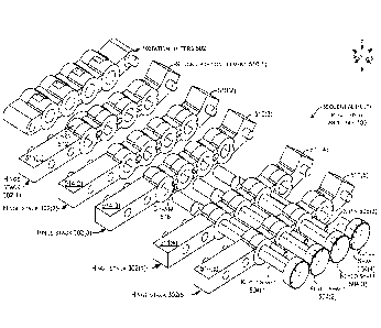
[0003] FIGS. 5-6 are perspective views and FIG. 7 is an exploded
perspective view
of a sequential multi- pivot hinge assembly example in accordance with some
implementations of the present concepts.
[0004] FIG. 8 is an exploded perspective view of an individual hinge
stack
example introduced in FIG. 7.
[0005] FIG. 8A is a perspective view of an individual link from FIG.
8.
[0006] FIGS. 9-10 show elevational views of a sequential multi- pivot
hinge
assembly example in accordance with some implementations of the present
concepts.
DESCRIPTION
[0007] The present concepts relate to computing devices employing multi-
pivot or
multi-axis hinge assemblies to rotatably secure portions of the computing
device. The
present hinges can be thought of as sequential hinges in that the multi-pivot
hinge
assemblies can control a relative order in which individual hinges rotate. One
such
configuration can cause the hinges to operate in a predefined order from first
to last (e.g.,
sequentially). As such, the multi-pivot hinge assemblies can be termed
'sequential multi-
pivot hinge assemblies'.
[0008] Introductory FIGS. 1-3 collectively show an example of a
computing
device 100. In this example, computing device 100 has first and second
portions 102 and
104 that are rotatably secured together by a sequential multi-pivot hinge
assembly 106.
FIGS. 1-2 show the computing device in a 'closed' position. FIG. 1 shows the
computing
device 100 from the 'front' and FIG. 2 shows the computing device from the
'back.' FIG. 3
is a
la
Date recue/ date received 2022-02-18
CA 02965708 2017-04-24
WO 2016/085697 PCT/1JS2015/060959
partial cut-away perspective view that shows the computing device in an 'open'
or
'deployed' position. In this example, in the deployed position, the first and
second
portions can define an obtuse angle a relative to one another, as opposed to
an angle close
to zero in the closed position of FIGS. 1-2. In other implementations, the
deployed
position can be 90 degrees or less or 180 degrees or more (e.g., a book like
configuration).
For instance, the deployed position may be somewhere in the range of 90
degrees to 180
degrees that is a comfortable viewing angle for the user.
[0009] As can be appreciated from FIG. 3, the sequential multi-pivot
hinge assembly
106 can include multiple hinge stacks 302. Aspects of the sequential multi-
pivot hinge
assembly 106 arc described in more detail below relative to FIGS. 5-10. In
this example,
the sequential multi-pivot hinge assembly includes rigid articulating hinge
covers 304 that
can obscure and/or protect the underlying elements, including the hinge stacks
302. Other
implementations do not include the rigid articulating covers. Still other
implementations
can include a flexible hinge cover that extends between the first portion 102
and the
second portion 104 over the sequential multi- pivot hinge assembly 106.
[00010] As evidenced in FIG. 3, computing device 100 can also include an input
element or device 308. In this case the input device 308 is manifest as a
keyboard 310.
Other implementations can employ other input devices. In this example, the
computing
device can also include a display screen 312, such as a touch sensitive
display screen. The
computing device can also include a processor 314, memory/storage 316, a
battery 318,
and/or a video or graphics processor 320, among other components/elements.
These
elements can be positioned in the first portion 102 and/or second portion 104.
[00011] In this case, the second portion 104 can be configured to be
positioned on a
generally horizontal surface (not specifically designated), such as a table
top. In the closed
position of FIGS. 1-2, the first and second portions are generally parallel to
one another
and the horizontal surface (e.g., the first portion is juxtaposed over the
second portion). In
contrast, in the deployed position of FIG. 3, the first portion is rotated
away from the
second portion, in this case to an obtuse angle.
[00012] Note that in the closed position of FIGS. 1-2, the sequential multi-
pivot hinge
assembly 106 can provide a footprint E that is compact and easy to carry. Note
also, that
in this implementation the progressive or sequential nature of the sequential
multi-pivot
hinge assembly 106 can increase or expand the footprint of the computing
device when the
device is transitioned from the closed or storage position of FIGS. 1-2 to the
open or
deployed position of FIG. 3. For example, compare the closed footprint E to
the deployed
2
CA 02965708 2017-04-24
WO 2016/085697 PCT/US2015/060959
or expanded footprint fd. This extended footprint feature can be especially
valuable in this
implementation where some or all of the electronic components, such as the
display 312,
processor 314, memory/storage 316, and battery 318 are positioned in the first
portion
102. The extended footprint provided by the sequential multi-pivot hinge
assembly can
increase stability of the computing device and reduce the likelihood of the
device tipping
over backward in the deployed position from the weight of these components.
Stated
another way, the sequential nature of the sequential multi-pivot hinge
assembly can create
a foot 322 in the deployed position that can help stabilize the computing
device 100 and
decrease tipping (e.g., maintain the center of mass over the footprint).
[00013] In the implementation shown in FIG. 3, the sequential multi-pivot
hinge
assembly 106 can be secured to the first and second portions 102 and 104 in a
relatively
permanent manner (e.g., in a manner that is not intended to be readily
separable by an end
use consumer). Alternatively, the sequential multi-pivot hinge assembly 106
can be
secured to the first and second portions 102 and 104 in a relatively quickly
attachable/detachable manner (e.g., in a manner that is intended to be readily
separable by
the end use consumer). One such example of this latter configuration is shown
in FIG. 4.
[00014] FIG. 4 shows another computing device 100A in a view that is similar
to the
view of FIG. 3. In this example, the sequential multi-pivot hinge assembly
106A is
configured to allow an end use consumer to easily detach either or both of the
first and
second portions 102 and 104 from the sequential multi-pivot hinge assembly
106A as
indicated by arrow 402. In this example the sequential multi-pivot hinge
assembly 106 can
include a quick attach/detach assembly 404. The quick attach/detach assembly
404 may
include cooperatively operating elements 406 and 408 located on the first
portion 102 and
the sequential multi-pivot hinge assembly 106A, respectively.
[00015] In one example, element 406 can be manifest as a latch and element 408
can be
manifest as a receiver. The latch can engage the receiver to removeably couple
the first
portion 102 with the sequential multi-pivot hinge assembly 106A. In another
example, the
elements 406 and 408 may magnetically couple to one another in a manner that
can be
overcome by the user to separate the first portion from the sequential multi-
pivot hinge
assembly 106A. Other quick attach/detach assemblies 404 are contemplated. The
sequential multi-pivot hinge assembly 106A may detachably connect with either
or both of
the first and/or second portions. Alternatively or additionally to mechanical
coupling, the
quick attach/detach assembly 404 can detachably electrically couple electronic
components of the first and second portions. For instance, the quick
attach/detach
3
CA 02965708 2017-04-24
WO 2016/085697 PCT/1JS2015/060959
assembly 404 may electrically couple processor 314, storage/memory 316, and/or
battery
318 from the first portion 102 to the graphics processor 320 and/or keyboard
310 in the
second portion 104.
[00016] Thus, the quick attach/detach assembly 404 can allow the user to be
able to
detach first portion 102 or second portion 104 to use either portion
independently of the
other. For example, first portion 102 may be operated as a stand-alone tablet
device, and
then may be attached to second portion 104 via sequential multi-pivot hinge
assembly
106A to form a device more akin to a laptop device. A user may also be able to
exchange
first portion 102 or second portion 104 for application-specific devices. For
example, an
.. individual second portion may include a keyboard and/or a touchscreen. In
certain
scenarios, the user may attach a first touchscreen as the first portion and a
second
touchscreen as the second portion, and utilize the device like a book. In
other scenarios, a
user may attach a touchscreen as the first portion and an input device,
manifest as a
keyboard and trackpad, as the second portion, and utilize the device like a
laptop. Other
configurations and implementations are contemplated.
[00017] FIGS. 5-10 collectively illustrate more details about the example
sequential
multi-pivot hinge assembly 106 including the hinge stacks 302 introduced above
relative
to FIG. 3. Note that due to space constraints on the drawing pages, not all
elements are
labeled in each FIG. and not every instance of every element is labeled,
rather
representative elements are labeled. FIG. 5 shows the sequential multi-pivot
hinge
assembly 106 in a closed or storage position similar to FIG. 1. FIG. 6 shows
the sequential
multi-pivot hinge assembly 106 in an open or deployed position similar to FIG.
3. FIG. 7
shows an exploded view similar to the view of FIG. 6. FIG. 8 is an exploded
view of an
individual hinge stack 302(5).
[00018] Referring to FIGS. 5-8, the example sequential multi-pivot hinge
assembly 106
can include rotation limiters 502, keyed shafts 504, sequencing pins 506 (FIG.
7).
Individual hinge stacks 302 can include a first portion element 510, multiple
radially
arranged links 512, and a second portion element 514. The keyed shafts 504
pass through
the hinge stacks 302 and the rotation limiters 502. The keyed shafts 504
define the axes of
rotation the links 512 rotate (or pivot) around. The sequencing pins can be
thought of as a
type of locking cam member that reside in channels 516 (FIG 7) formed through
the links
512. Various types of rotation limiters 502 can be utilized. As illustrated
relative to FIG. 6,
individual rotation limiters can define the degrees of rotation b (FIG. 6)
around an
individual axis of rotation.
4
CA 02965708 2017-04-24
WO 2016/085697 PCT/1JS2015/060959
[00019] FIG. 8 shows a partially exploded individual hinge stack 302(5). In
this case,
link 512(5)A is positioned against second portion element 514(5). In this view
the second
portion element 514(5) is shown with cross-hatching to aid the reader in
distinguishing the
second portion element from the link 512(5)A. Note that individual links 512
have an
offset configuration with a first region 802 connected to a second region 804
by a central
region 806. Note that FIG. 8 includes a large number of structures and
designators. For
clarity purposes, FIG. 8A shows an individual link 512(5) in isolation with
the individual
first region 802, second region 804 and central region 806 circled. From one
perspective
the offset nature of the individual links can be characterized as
approximating a portion of
a lightning bolt shape (e.g., when viewed along the xz reference plane).
[00020] Referring to FIG. 8 and FIG. 8A, the first region 802 can define a
first
passageway 808. Similarly, the second region 804 can define a second
passageway 810
that is parallel to the first. The first region 802 of an individual link,
such as link 512(5)B
can be aligned with the second region 804 of an adjacent link, such as link
512(5)A to
.. receive an individual keyed shaft 504, such as keyed shaft 504(2) as
indicated by arrow
812.
[00021] The link's central region 806 can extend generally parallel to a hinge
axis
defined by the keyed shaft 504. As such, the central region 806 can extend
generally
parallel to the keyed shaft 504 to support an offset configuration of the link
512(5) where
the first and second regions 802 and 804 can define parallel but offset
passageways 808
and 810. Thus, in this example, as mentioned above, first region 802 of link
512(5)B can
be positioned against the second region of link 512(5)A to receive keyed shaft
504(2) as
indicated by arrow 812. The first region 802 of link 512(5)A can in turn be
aligned with
the second portion element 514(5). The second portion element can include a
terminus
814. The terminus can define a passageway 816. Keyed shaft 504(1) can pass
through the
passageway 816 and passageway 808 of link 822(2)A (passageway 808 of link
822(2)A is
not visible, but the passageway is designated relative to link 512(5)B) to
rotatably join the
second portion element 514(5) to the link 512(5)A as indicated by arrow 818.
Similarly,
keyed shaft 504(3) can rotatably join the second region 804 of link 512(5)B to
the first
region 802 of link 512(5)C as indicated by arrow 820.
[00022] Note that in this implementation, the keyed shafts 504 do not have a
circular
profile when viewed transverse their long axis (e.g., when viewed along the xz
reference
plane). Instead in this case, the keyed shafts have a profile that
approximates a capital "D".
Second passageway 810 has a similar profile so that the keyed shaft is keyed
or locked
5
CA 02965708 2017-04-24
WO 2016/085697 PCT/1JS2015/060959
relative to the second region 804. In contrast, the first passageway 808 has a
circular
profile. This configuration can allow the 'back' link to rotate around the
keyed shaft while
preventing the 'front' link from rotating around the keyed shaft. Thus, it is
contemplated
that other keyed shaft profiles can be utilized that cause the keyed shaft to
be non-rotatable
relative to a first link and rotatable relative to a second link. For
instance, a star shaped
profile could be utilized where the front link's passageway matches the star
profile and the
back link is circular with a diameter defined by the outer points of the star.
[00023] An individual link 512, such as link 512(5)B can define a number of
cam
surfaces 822. In this example, the link can define four designated cam
surfaces 822. A first
individual cam surface 822(1) can be formed in first region 802 proximate to
central
region 806. A second individual cam surface 822(2) can be formed in the first
region 802
away from the central region. Similarly, a third individual cam surface 822(3)
can be
formed in the second region 804 proximate to the central region 806 and a
fourth
individual cam surface 822(4) can be formed in the first region 802 away from
the central
region. Note that cam surfaces 822(1) and 822(3) of an individual link 512(5)
can partially
define channel 516 and thus prescribe a fore-aft translational degree of
freedom (e.g., in
the x reference direction relative to FIG. 8) for an individual sequencing pin
506. Thus, in
some cases, as will be described in more detail below, cam surfaces 822(1) and
822(3)
simply define channel 516 (FIG. 7), while surfaces 822(2) and 822(4) are
involved in
controlling rotation by individual links. Also note that not all cam surfaces
are specifically
discussed and designated. For instance, an additional cam surface 823
(designated only
relative to link 512(5)C can work cooperatively with cam surface 822(2)C to
move
sequencing pin 506(2) translationally (e.g., in the negative x reference
direction relative to
FIG. 8). Note also that first portion element 510(5) has a cam surface 824
that operates
cooperatively with link 512(5)C and second portion element 514(5) has a cam
surface 826
that operates cooperatively with link 512(5)A to receive sequencing pin 506(1)
as
indicated by arrow 828. From one perspective, the cam surfaces and sequencing
pins can
function as a rotation control element or rotation control sub-assembly 830.
For instance,
cam surface 822(4)A of link 512(5)A, cam surface 822(2)C of link 512(5)C, and
sequencing pin 506(2) function as rotation control element 830(2) to control
when rotation
occurs around the rotation axis defined by keyed shaft 504(3) relative to
rotation around
keyed shafts 504(2) and 504(4) (FIG. 7). Other rotation control elements 830
are
contemplated.
6
CA 02965708 2017-04-24
WO 2016/085697 PCT/1JS2015/060959
[00024] FIG. 9 shows sectional views of hinge stack 302(5) in three positions.
These
sectional views are taken along the xz reference plane. Position One is
analogous to the
closed position of FIG. 5. In this case, a force is being applied to the hinge
stack in the
positive x direction. Relative to rotation control elements 830(1) the force
can cause link
512(5)A to rotate around keyed shaft 504(1). However, note that relative to
rotation
control elements 830(2), rotation around keyed shaft 504(2) is blocked because
sequencing pin 506(1) is engaging cam surface 822(2)B (hidden from view in
FIG. 9, see
FIG. 8) of link 512(5)B. Sequencing pin 506(1) cannot be cammed away from cam
surface
822(2)B because at this point the sequencing pin 506(1) is not aligned with
cam surface
826 of terminus 814. Similarly, relative to rotation control elements 830(3)
(Position Two)
sequencing pin 506(2) is blocking rotation around keyed shaft 504(3) since
sequencing pin
506(2) is engaging cam surface 822(2)C (see FIG. 8) of link 512(5)C and is not
aligned
with cam surface 822(4)A of link 512(5)A.
[00025] Position Two shows rotation around keyed shaft 504(1) to a point where
camming surface 826 is aligned with sequencing pin 506(1) and camming surface
822(2)B
of link 512(5)B (hidden from view). At this point, the force can begin to
cause rotation
around keyed shaft 504(2) and camming surface 822(2)B of link 512(5)B (See
FIG. 8) can
cam (e.g., move) sequencing pin 506(1) in the negative x reference direction
(e.g., toward
camming surface 826) and continue rotating around keyed shaft 504(2).
[00026] Position Three is an intermediary position (e.g., partially deployed)
between
the closed position of FIG. 5 and the deployed position of FIG. 6 and shows
rotation
around keyed shaft 504(3) to a point where cam surface 822(4) of link 512(5)A
is aligned
with sequencing pin 506(2). Because there is now a place for sequencing pin
506(2) to
move to, the force can cause camming surfaces 822(2)C and 823 (see FIG. 8) of
link
512(5)C to cam the sequencing pin in the negative x reference direction as
rotation
commences around keyed shaft 504(3). This process can be repeated for
sequencing pin
506(3) and keyed shaft 504(3).
[00027] Thus, starting in the closed position of Position One, when a force is
applied to
the hinge stack 302(5) (e.g., to the sequential multi-pivot hinge assembly)
rotation starts at
the hinge axis (e.g., keyed shaft 504(1)) closest to the second portion 104.
Rotation around
the next closest hinge axis cannot commence until rotation around the closest
hinge axis
has completed a defined range of rotation of the camming surfaces (See angle c
of FIG.
10. FIG. 10 is similar to Position One of FIG. 9). This process is repeated in
a sequential
manner from closest to the second portion to furthest from the second portion.
In a similar
7
CA 02965708 2017-04-24
WO 2016/085697 PCT/1JS2015/060959
manner when the process is reversed to close the computing device, rotation
begins around
the hinge axis furthest from the second portion and moves toward the second
portion only
as each hinge axis completes its defined rotation and the respective
sequencing pin 506
can move in the positive x reference direction. Thus, the rotation control
elements can
control the relative order of rotation around individual hinge axes of hinge
stacks 302 of
the sequential multi-pivot hinge assembly 106 (FIG. 7).
[00028] Thus, some implementations of the sequential multi-pivot hinge
assembly can
employ sliding sequencing elements, such as pins, that cam off opposing link
cam surfaces
to lock and unlock individual sequencing pins. This configuration can allow
the sequential
multi-pivot hinge assembly to roll and unroll in a controlled sequential
manner that
enables the hinge to be used as a foot to support a laptop like device, for
example. The
unrolling action can move the device fulcrum backwards providing a longer
wheel base
(e.g., extended footprint) for the device in turn making the device less
likely to tip over
when a user interacts with the touch screen.
[00029] Further, some implementations of the sequential multi-pivot hinge
assembly
can include multiple pivots or axes of rotation and links. Between each pivot,
individual
links can have a sliding (or otherwise moving) rotation locking element that
is moved into
position via camming action embedded within the links that forces the rotation
locking
element fore and aft to lock and unlock connecting links. The rotation locking
element can
enable communication between links to enable only one active pivot at a time.
EXAMPLE METHODS
[00030] Various methods of manufacture, assembly, and use for
sequential multi-
pivot hinge assemblies are contemplated beyond those shown above relative to
FIGS 1-10.
ADDITIONAL EXAMPLES
[00031] Various examples are described above. Additional examples are
described
below. One example is manifest as a first portion that includes a display
screen and a
second portion that includes an input device. This example also includes a
sequential
multi-pivot hinge assembly rotatably securing the first portion and the second
portion from
a storage position where the first portion is juxtaposed over the second
portion to a
deployed position where the first portion is oriented at an obtuse angle
relative to the first
portion. The sequential multi-pivot hinge assembly can include multiple hinge
stacks and
rotation control elements. Individual hinge stacks can be coupled to the first
and second
portions and can include multiple radially arranged links that rotate around
individual
hinge axes. Individual rotation control elements can be interposed between
individual
8
CA 02965708 2017-04-24
WO 2016/085697 PCT/1JS2015/060959
adjacent links to control a relative order of rotation of the individual
adjacent links
depending upon whether the first portion and second portion are being rotated
from the
storage position to the deployed position or from the deployed position to the
storage
position
1000321 Any combination of the above and/or below examples where the
rotation
control elements comprise sequencing pins.
[00033] Any combination of the above and/or below examples where the
individual
links have opposing offset first and second regions connected by a central
region.
Individual first regions can define first passageways and individual second
regions define
second passageways that arc parallel to the first passageways. An individual
first region of
an individual first link can be rotatably secured to an individual second
region of an
individual second link by a shaft that defines an individual axis of rotation
of the
sequential multi-pivot hinge assembly. An individual second region of a third
individual
link can be secured to a first region of the second individual link via a
second shaft.
[00034] Any combination of the above and/or below examples where the
central
region of the first link partially defines a channel in which an individual
sequencing pin
resides and wherein the individual first region of the individual first link
defines a first
cam surface and the individual second region of the third individual link
defines a second
cam surface. Also, a relative position of the individual sequencing pin
relative to the first
and second cam surfaces can determine whether the second individual link can
rotate
relative to the first individual link.
[00035] Any combination of the above and/or below examples where the
shaft has a
circular profile when viewed transverse the axis of rotation or wherein the
shaft is not
circular.
[00036] Any combination of the above and/or below examples where the shaft
is
key shaped and a profile of an individual first passageway of the first link
matches a
profile of the shaft and a profile of an individual second passageway of the
second link is
circular.
[00037] Any combination of the above and/or below examples where the
rotation
control elements prevent rotation around a second individual hinge axis until
a first
individual hinge axis has completed a defined number of degrees of rotation.
[00038] Any combination of the above and/or below examples where the
sequential
multi-pivot hinge assembly is configured to create a larger footprint of the
computing
device in the deployed position than in the storage position.
9
CA 02965708 2017-04-24
WO 2016/085697 PCT/1JS2015/060959
[00039] Any combination of the above and/or below examples where the
sequential
multi-pivot hinge assembly further comprises a rotation limiter to limit
rotation around
each axis of rotation to a defined number of degrees.
[00040] Any combination of the above and/or below examples where the
sequential
multi-pivot hinge assembly is visible when in both the storage position and
the deployed
position.
[00041] Any combination of the above and/or below examples further
including a
hinge cover.
[00042] Any combination of the above and/or below examples where the
hinge
cover comprises multiple rigid hinge covers or wherein the hinge cover
comprises a
flexible hinge cover that extends from the first portion to the second
portion.
[00043] Another example is manifest as a first portion and a second
portion. The
example can include a sequential multi-pivot hinge assembly rotatably securing
the first
portion and the second portion and including rotation control elements
configured to
control a relative order of rotation around axes of rotation of the sequential
multi-pivot
hinge assembly.
[00044] Any combination of the above and/or below examples where the
rotation
control elements comprise locking cam members that engage cam surfaces defined
on
links that rotate around individual axes of rotation.
[00045] Any combination of the above and/or below examples where the
locking
cam members comprise elongate sequencing pins oriented parallel to the axes of
rotation
of the sequential multi-pivot hinge assembly.
[00046] Any combination of the above and/or below examples where the
second
portion defines a footprint of the computing device when the first portion is
juxtaposed
over the second portion in a storage position and when the first portion is
rotated away
from the second portion to an obtuse angle, the rotation control elements
expand the
footprint.
[00047] Any combination of the above and/or below examples further
including
electronic components positioned in the first portion and wherein a center of
mass of the
computing device is located above the expanded footprint.
[00048] Any combination of the above and/or below examples where the
rotation
control elements only allow rotation around a single axis of rotation at a
time.
[00049] Another example is manifest as a first portion and a second
portion. The
example can include a sequential multi-pivot hinge assembly rotatably securing
the first
CA 02965708 2017-04-24
WO 2016/085697 PCT/1JS2015/060959
portion and the second portion to control rotation around individual axes
starting
proximate to the second portion when rotating the first and second portions
apart and
starting proximate to the first portion when moving the first and second
portions toward
one another.
[00050] Any combination of the above and/or below examples where the
sequential
multi-pivot hinge assembly includes rotation control elements. When the first
and second
portions are moving apart, the rotation control elements prevent rotation
around an
individual axis that is proximate to the first portion until rotation around
another individual
axis that is proximate to the second portion has completed a defined angle of
rotation.
When the first and second portions arc moving toward one another the rotation
control
elements prevent rotation around the another individual axis until rotation
around the
individual axis has completed the defined angle of rotation.
[00051] Another example is manifest as a first portion and a second
portion. The
example can include a sequential multi-pivot hinge assembly rotatably securing
the first
portion and the second portion and configured to extend a footprint of the
computing
device when the first and second portions are rotated away from one another
and to
contract the footprint when the first and second portions are rotated toward
one another.
[00052] Another example is manifest as a hinge having a first interface
and a
second interface. The hinge can also have a sequential multi-pivot hinge
assembly
rotatably securing the first interface and the second interface to control
rotation around
individual axes starting proximate to the second interface when rotating the
first and
second interfaces apart and starting proximate to the first interface when
moving the first
and second interfaces toward one another
[00053] Any combination of the above and/or below examples where the
sequential
multi-pivot hinge assembly comprises rotation control elements. When the first
and
second interfaces are moving apart, the rotation control elements prevent
rotation around
an individual axis that is proximate to the first interface until rotation
around another
individual axis that is proximate to the second interface has completed a
defined angle of
rotation. When the first and second interfaces are moving toward one another
the rotation
control elements prevent rotation around the another individual axis until
rotation around
the individual axis has completed the defined angle of rotation.
[00054] Any combination of the above and/or below examples where the
first
interface comprises an electrical connector and a mechanical latch.
11
CA 02965708 2017-04-24
WO 2016/085697 PCT/1JS2015/060959
CONCLUSION
[00055] Although techniques, methods, devices, systems, etc., pertaining to
sequential
multi-pivot hinge assemblies are described in language specific to structural
features
and/or methodological acts, it is to be understood that the subject matter
defined in the
appended claims is not necessarily limited to the specific features or acts
described.
Rather, the specific features and acts are disclosed as exemplary forms of
implementing
the claimed methods, devices, systems, etc.
12