Note: Descriptions are shown in the official language in which they were submitted.
CA 2966104 2017-05-02
ENVIRONMENTAL CONTROL FOR MEDIUM-VOLTAGE DRIVE
TECHNICAL FIELD
Embodiments of the present disclosure relate to medium-voltage drives and,
more
particularly, to an environmental control system and method for use in outdoor
medium-
voltage drives.
BACKGROUND
Medium-voltage (e.g., greater than 1500 volts) power electronics assemblies,
such
as adjustable speed drives, often use groups of power transistors and diodes
switched on
and off in a predetermined timing sequence to supply the level and frequency
of power
desired. Because of the high voltage levels in which they operate (e.g., 2400
volts, 3300
volts, 4160 volts, 6600 volts, etc.), and the associated levels of current,
these devices tend
to generate significant amounts of excess heat.
It is desirable to dissipate the excess heat generated by such medium-voltage
drives throughout their operation. Known methods for dissipating the excess
heat involve
using a fan to draw air through the cabinet housing the power devices of the
medium-
voltage drive. Doing so, however, results in airborne contaminants being
deposited on
the power devices such that, over time, the devices will require maintenance
and/or
cleaning. The contaminants may also interfere with the operation of the
devices, or may
cause even more heat to build up (e.g., as the contaminants may tend to trap
heat) and
reduce the lifespan of the devices. Controlling the operating environment of
the power
devices becomes even more complicated when the medium-voltage drives are
housed in
outdoor units and exposed to extreme cold ambient conditions.
SUMMARY
In accordance with the above, presently disclosed embodiments are directed to
a
system and method for controlling the temperature of medium-voltage power
electronics
assemblies (i.e., medium-voltage drives). The system and method may be
particularly
useful in outdoor medium-voltage drives that are exposed to very cold ambient
temperatures. The disclosed system generally includes a medium-voltage drive
having
one or more cabinets with power electronics devices disposed therein, one or
more fans
for circulating air through the cabinets or heatsinks to cool the devices, and
one or more
1
CA 2966104 2017-05-02
space heaters disposed in the cabinet. The medium-voltage drive also features
temperature sensors used to measure various temperatures (e.g., ambient
temperature,
device temperature, coolant temperature) of the drive, a controller (e.g.,
programmable
logic controller) communicatively coupled to the sensors, and one or more
variable
frequency drives (VFD) for the one or more fans. The controller outputs
control signals
to the VFD and the one or more space heaters to adjust a temperature of the
medium-
voltage drive as needed to keep the drive and components within a desired
operating
temperature range. The controller may receive measurements regarding the
ambient and
power device temperatures and apply controls to vary the space heater power
and fan
speed in response to environmental changes.
BRIEF DESCRIPTION OF THE DRAWINGS
For a more complete understanding of the present disclosure and its features
and
advantages, reference is now made to the following description, taken in
conjunction with
the accompanying drawings, in which:
FIG. 1 is a schematic diagram illustrating a medium-voltage drive, in
accordance
with an embodiment of the present disclosure;
FIG. 2 is a schematic diagram illustrating the associated environmental
control
system, in accordance with an embodiment of the present disclosure;
FIG. 3 is a schematic diagram illustrating the environmental control system of
FIG. 2, in accordance with an embodiment of the present disclosure;
FIG. 4 is a process flow diagram of a method for operating the environmental
control system of FIG. 2, in accordance with an embodiment of the present
disclosure;
and
FIG. 5 is a plot illustrating a control scheme for varying a fan speed in the
medium-voltage drive of FIG. 2, in accordance with an embodiment of the
present
disclosure.
DETAILED DESCRIPTION
Illustrative embodiments of the present disclosure are described in detail
herein.
In the interest of clarity, not all features of an actual implementation are
described in this
specification. It will of course be appreciated that in the development of any
such actual
embodiment, numerous implementation specific decisions must be made to achieve
2
CA 2966104 2017-05-02
developers' specific goals, such as compliance with system related and
business related
constraints, which will vary from one implementation to another. Moreover, it
will be
appreciated that such a development effort might be complex and time
consuming, but
would nevertheless be a routine undertaking for those of ordinary skill in the
art having
the benefit of the present disclosure. Furthermore, in no way should the
following
examples be read to limit, or define, the scope of the disclosure.
Medium-voltage drives often include groups of power transistors and diodes
switched on and off in a predetermined timing sequence to supply the level and
frequency
of power desired. These medium-voltage drives are sometimes located in a
cabinet
positioned outdoors. Outdoor medium-voltage drives often utilize space heaters
to heat
the cabinet during extreme cold conditions as well as fans to cool the power
devices
therein. In existing systems, control of the space heaters and fans is
typically simple,
such that the space heaters are turned on when the drive is off/cold and the
fans run
constantly at one speed whenever the drive is running/hot. However, this type
of
temperature control can cause large temperature swings of the power devices,
which can
lead to inefficient operation or damage to the power devices. The existing
temperature
control methods can also reduce the cooling capabilities of single-phase and
two-phase
heat sinks coupled to the power devices.
The disclosed environmental control system and method are designed to overcome
these drawbacks associated with existing systems. The environmental control
system
may include a controller that uses signals received from device temperature
sensors and
ambient temperature sensors to determine and output control signals to one or
more
variable frequency drives (VFD) for the cooling fan or fans and to one or more
space
heaters disposed in the cabinet. The disclosed environmental control system
and method
may provide more gradual temperature adjustments within the drive system to
prevent
large temperature swings, as compared to existing control systems. The
environmental
control system and method may provide reliable temperature control by varying
both fan
speed and space heater operating power to maintain the power devices within a
desired
temperature range. The fan may be operated at a speed just fast enough to keep
the
electronics within a preferred temperature range while reducing the amount of
debris
pulled into the drive cabinet or heatsinks, thus reducing the need for
periodic cleaning.
This may keep the drive power devices operating more efficiently and longer
than would
be available with a single speed fan.
3
CA 2966104 2017-05-02
Turning now to the drawings, FIG. 1 is a schematic block diagram of a medium-
voltage drive system 10 in accordance with the disclosed embodiments. The
medium-
voltage drive system 10 may be an indoor or outdoor unit. The medium-voltage
drive
system 10 may include a cabinet 12 (or enclosure) housing a group of power
devices 14.
These power devices 14 may include, for example, power transistors and diodes
designed
to be switched on and off in a predetermined timing sequence to supply a
desired level
and frequency of power. In some embodiments, the devices 14 may be attached to
a heat
sink 16 as shown. The heat sink 16 may be used to help cool the power devices
14. The
heat sink 16 may be any desirable type of heat sink including, but not limited
to, a simple
heat conductive metal heat sink, a liquid cooled single phased heat sink, or a
boiling type
two phase heat sink.
In addition to the heat sink 16, the medium-voltage drive system 10 includes a
fan
assembly 18 that may be used to draw air through the cabinet 12, the heatsink
16, or both
to dissipate the excess heat generated by the power devices 14, thereby
cooling the
devices 14. The fan assembly 18 may include one or more fans for directly or
indirectly
(e.g., via heat sink 16) cooling the devices 14. The medium-voltage drive
system 10 is
designed for effective operation in extremely cold environments. To that end,
the
medium-voltage drive system 10 includes one or more space heaters 20 disposed
within
the cabinet 12. The space heaters 20 may be operated by running an electric
current
through high resistance heating elements. In some embodiments, the space
heaters 20
may include fans that help distribute heat from the heating elements to the
cabinet 12.
The one or more space heaters 20 may be turned on and controlled to increase
the
ambient temperature within the cabinet 12. This heating of the cabinet 12 may
enable
effective operation, and in extreme cases, prevent low temperature failure of,
the power
devices 14 and the attached heat sink 16 when the medium-voltage drive 10 is
exposed to
very cold outdoor temperatures.
As illustrated, at least one ambient temperature sensor 22 and at least one
device
temperature sensor 24 may be disposed within the cabinet 12 of the medium-
voltage drive
10. The ambient temperature sensor 22 may be used to detect a temperature of
the
ambient air within the cabinet 12, while the device temperature sensor 24 may
be
positioned to detect a temperature of the power devices 14. In some
embodiments,
another temperature sensor (not shown) may be coupled to a portion of the heat
sink 16,
such as a sensor used to measure a temperature of coolant being cycled through
the heat
4
CA 2966104 2017-05-02
sink 16 to cool the devices 14. Each of the temperature sensors 22 and 24 of
the medium-
voltage drive 10 may be communicatively coupled to a controller, as described
in greater
detail below. The controller may utilize the temperature measurements to
execute
improved control over the operation of the one or more fans in the fan
assembly 18 as
well as the one or more space heaters 20.
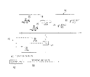
FIG. 2 is a detailed schematic of an environmental control system 50 that may
be
used to control the temperature of various components within the medium-
voltage drive
of FIG. 1. The environmental control system 50 may include at least one fan
18, the
space heaters 20, the ambient temperature sensor 22, the device temperature
sensor 24,
10 and a controller 52. The ambient and device temperature sensors 22 and
24 may each
include a resistance temperature detector (RTD). In the disclosed embodiment,
the fan 18
may be coupled to a variable frequency drive (VFD) 54, which is used to
selectively vary
the rotational speed of the fan 18 and, thus, the speed of air moving through
the cabinet
12. When multiple fans 18 are used, each may be coupled to a separate VFD 54
for
selectively varying the speeds of the fans 18.
Each of the space heaters 20 may be coupled to a corresponding heater power
control component 56 that is used to vary the amount of heat output from the
space heater
20. For example, based on a control signal received at the heater power
control 56, the
heater power control 56 may operate the corresponding space heater 20 at one
of a
number of available heater power levels. For example, the space heaters 20 may
be
designed to work at a low, medium, and high heat level, based on the setting
of the heater
power control 56. The heater power control 56 may facilitate changes in the
amount of
heat output from the space heater 20, for example, by varying an amount of
electric
current flowing through the heating element of the space heater 20. A fan (not
shown)
may be added to help circulate the heat through the cabinet.
As illustrated, the controller 52 is communicatively coupled to both the
ambient
temperature sensor 22 and the device temperature sensor 24. The controller 52
receives
temperature input signals 58 from these sensors 22 and 24. The controller 52
may also be
communicatively coupled to the VFD 54 of the fan assembly 18 and the heater
power
control components 56 used for each space heater 20 in the medium-voltage
drive 10.
The controller 52 may provide control output signals 60 to the VFD 54 and the
heater
power controls 56 to adjust a temperature within the medium-voltage drive 10.
The
controller 52 may measure the ambient and power device temperatures via
sensors 22 and
5
CA 2966104 2017-05-02
24 and apply control signals to the space heater power components 56 and the
fan VFD
54 in response to environmental changes detected through the temperature
measurements.
The controller 52 may output signals for independently controlling operation
of the one or
more cooling fans 18 and the space heaters 20 in the medium-voltage drive 10.
FIG. 3 illustrates a more detailed view of the controller 52 described above.
As
illustrated, the controller 52 may include a computing device for controlling
the operation
of the fan assembly 18 (via the VFD 54) and one or more space heaters 20 in
the medium-
voltage drive 10. In some embodiments, the controller 52 may include a
programmable
logic controller (PLC). In other embodiments, the controller 52 may have
aspects of a
general purpose computer configured to operate in a manner similar to or in
combination
with a PLC. In one programmed arrangement, the controller 52 may vary the
speed of the
fan 18 and vary the heating power of the space heaters 20 in response to
ambient and/or
device temperature measurements.
Hardware components of the controller 52 may include a processing unit 90, a
system memory 92, and a system backplane 94 that forms a data pathway for an
input/output interface 96. The input/output interface 96 may communicate with
various
control devices, such as the VFD 54, the heater controls 56, the ambient
temperature
sensor 22, and the device temperature sensor 24. The processing unit 90 may be
a
suitable microprocessor used in industrial control systems. The system
backplane 94 may
be any of several types of conventional backplane structures. The system
memory 92
may include computer readable code in the form of read only memory (ROM) and
random access memory (RAM). The system memory 92 may store programmable
instructions of operational logic sequences 98 that are executed by the
processing unit 90.
The controller 52 may further include a computer readable storage device 100
that
may comprise an Eraseable Programmable Read Only Memory (EPROM), Electrically
Eraseable Programmable Read Only Memory (EEPROM), or battery backed-up RAM.
The storage device 100 and associated computer-readable media provide
nonvolatile
storage of computer readable code and operational logic sequences 98.
Nevertheless,
various operational logic sequences for the environmental control system 50
may be
readily programmed into the controller 52. In a further arrangement, the
controller 52
may operate in a networked environment 102 using a network interface 104. The
networked environment 102 may include a local area network (LAN) and any
number of
networking signaling protocols used in conventional industrial control
systems. For
6
CA 2966104 2017-05-02
example, the controller 52 may be configured with an operative connection to
an internet
protocol (IP) network which enables access for devices on the World Wide Web.
This
may allow operating data to be viewed from a remote location using a computer
terminal
106 running a conventional web browser.
A control operation provided by the disclosed environmental control system 50
may allow the fan speed of the fan 18 to be varied based on the detected
ambient/device
temperatures and the space heaters to be incrementally powered up in response
to lower
detected ambient temperatures. To facilitate these features, the present
disclosure
provides a computer implemented operation for the VFD 54 of the fan assembly
18 and
the one or more space heaters 20 in the medium-voltage drive 10. Operational
logic may
be described in the general context of computer-executable instructions, such
as program
modules, executed by one or more computing devices, such as the controller 52.
Generally, program modules may include routines, programs, objects,
components, data
structures, or ladder logic that perform particular tasks or implement
particular data types.
FIG. 4 illustrates a method 130 for controlling the operation of the fan VFD
54
and one or more space heaters 20 of the medium-voltage drive 10 described
above. It
should be noted that certain parts of the method 130 may be implemented as a
computer
or software program (e.g., code or instructions) that may be executed by the
processing
unit 90 in the controller 52 to execute one or more of the steps of the method
130.
Additionally, the program (e.g., code or instructions) may be stored in any
suitable article
of manufacture that includes at least one tangible non-transitory, computer-
readable
medium that at least collectively stores these instructions or routines, such
as the system
memory 92 or the storage device 100 in the controller 52. It should be noted
that
additional steps (or fewer steps) may be implemented in other embodiments of
the
environmental control method 130, and some of the illustrated steps may be
combined
together or performed in different orders than as shown.
The method 130 includes receiving temperature measurements 132 at the
processing unit 90 from the ambient temperature sensor 22, the device
temperature sensor
24, and/or any other sensors within the medium-voltage drive system 10. As
described
with reference to FIG. 2, these temperature measurements 132 may be
communicated as
temperature inputs 58 to the controller 52. The method 130 may then include
determining, based on the received temperature measurements 132, one or more
control
commands 134 to output to the various control components of the environmental
control
7
CA 2966104 2017-05-02
system 50. Specifically, the method 130 involves determining control commands
134 to
send to the fan VFD 54 as well as the one or more heater control components 56
of the
environmental control system 50. In some embodiments, the control commands 134
may
be to adjust (i.e., increase or decrease) a speed of the fan 18 via the VFD
54, to adjust
(i.e., increase or decrease) the amount of heating power output from the space
heaters 20
within the cabinet 12 of the medium-voltage drive 10, or both. Since the fan
18 and the
space heaters 20 are independently operated, the control commands 134 may be
to run
both the fan 18 and one or more space heaters 20 at the same time.
Based on the determined control commands, the environmental control system 50
may vary a fan speed (block 136) of the fan 18 (using the VFD 54) based on the
temperature measurements 132 to maintain the power devices 14 of the medium-
voltage
drive 10 in a predetermined operating temperature range. That is, the system
may control
the device-cooling fan speed (air flow) based on the ambient temperature
measurement,
the device temperature measurement, or both. This may involve increasing the
speed of
the fan 18 using the VFD 54 as the detected device temperature increases due
to higher
drive loads of the power devices 14 and/or increased ambient temperature.
In addition, varying the fan speed may include decreasing the speed of the fan
18
(or turning off the fan) using the VFD 54 as the detected device temperature
decreases
due to low use of the power devices 14 and/or decreased ambient temperature.
If coolants
are used in the heat sink 16 to cool the power devices 14, it is desirable and
sometimes
necessary to reduce the fan speed at very low ambient temperatures to keep the
coolant
viscosity within a desired operating range. Similarly, it is also desirable
and sometimes
necessary to reduce the fan speed at low ambient temperatures to keep the
temperature of
the power devices 14 within a desired operating range.
As an example of this fan speed control, FIG. 5 provides a plot 150
representing a
control scheme for the desired fan output based on a detected condenser
temperature 152.
The condenser temperature 152 may be equivalent or proportional to a device
temperature. For example, the condenser temperature 152 may measure a
temperature of
coolant in a condenser that is used to cool the power devices 14 (e.g., via a
fluid cooled
heat sink 16). In other embodiments, the temperature relationship may vary the
airflow
(fan speed) based on a temperature detected by a temperature sensor 24
positioned
directly at the heat sink 16 or devices 14, or based on the ambient
temperature sensor 22.
FIG. 5 plots a line 158 representing the output fan speed 154 (as a percentage
of
8
CA 2966104 2017-05-02
highest available fan speed) and the resulting airflow 156 (in meters cubed
per minute)
through the cabinet 12 based on the detected temperature 152. The controller
52 may
output signals to the VFD 54 to vary the fan speed 154 linearly within a
certain
temperature range 160. For example, the line 158 shows a linearly increasing
fan speed
154 across the condenser temperature range of -5 C to 35 C. Specifically,
the fan speed
154 varies from 0% (i.e., the fan 18 is off) at -5 C to 100% (i.e., fan
operating full-speed)
at 35 C. The fan 18 may remain off for all detected temperatures below -5 C
and full-
speed for all detected temperatures above 35 C. It should be noted that the
relationship
of FIG. 5 is merely an example, and other control schemes for varying fan
speed 154
based on detected temperatures 152 (or across different temperature ranges
160) may be
used in other embodiments.
The linear control of the fan speed 154 with respect to the detected
temperature
152 may be used to limit the fan speed 154 to only what is necessary for the
current
temperature conditions. That way, the control of the fan 18 may facilitate
reduced intake
of dust and other contaminants and reduced drive losses under low load or
temperature
conditions, as compared to existing systems that merely cycle a cooling fan
between
completely on and completely off. In other embodiments, the speed control may
also be
nonlinear.
Turning back to FIG. 4, the method 130 may further include steps to maintain
the
power devices 14 of the medium-voltage drive 10 within a desired operating
temperature
range during exposure to extremely cold ambient temperatures. At extremely low
ambient temperatures, the controller 52 may output signals to incrementally
increase
power (block 138) to the space heaters 20 in the medium-voltage drive 10 in
response to
decreasing ambient temperatures. For example, the controller 52 may output
signals to
incrementally increase power (block 138) to the space heaters 20 when the
detected
ambient temperature dips below certain temperature thresholds. In some
embodiments,
the controller 52 may incrementally increase space heater power by turning on
an
additional space heater 20 disposed in the cabinet 12 each time the ambient
temperature
decreases below another temperature threshold. In other embodiments, the
controller 52
may incrementally increase space heater power by turning one or more space
heaters 20
from a low setting to a medium setting to a high setting each time the ambient
temperature decreases below another threshold.
The method 130 may also include preventing the power devices 14 of the
9
CA 2966104 2017-05-02
medium-voltage drive 10 from operating (block 140) until the detected device
temperature reaches above a rated minimum operating temperature. For example,
if the
medium-voltage drive 10 has been off for some time period during extremely
cold
ambient temperatures, the controller 52 may output signals to the space heater
controls 56
to increase the temperature inside the cabinet 12 until the device temperature
(e.g.,
detected by sensor 24) is within an operating temperature range. The
controller may also
stop the drive if the temperature exceeds a desired maximum temperature.
Although the disclosure and its advantages have been described in detail, it
should
be understood that various changes, substitutions and alterations can be made
herein
without departing from the spirit and scope of the disclosure as defined by
the following
claims.