Note: Descriptions are shown in the official language in which they were submitted.
CA 02966456 2017-05-01
Doc. No.: 106-98 CA/PCT Patent
TRANSFORMER TEST DEVICE AND METHOD FOR TESTING A
TRANSFORMER
FIELD OF THE INVENTION
The invention relates to a transformer test device and to a method for testing
transformers. The invention relates, in particular, to devices and methods of
this kind
in which a winding of the transformer is short-circuited at least during a
portion of a
transformer test.
BACKGROUND
Transformers are used as constituent parts of energy supply systems.
Transformers
can be used for voltage conversion from a first value on a high-voltage side
to a
second value, which is smaller than the first value, on a low-voltage side.
Determining properties of a transformer by a transformer test, in which one or
more
characteristic variables of the transformer are ascertained by measurement, is
necessary, for example, for the purpose of ensuring operational reliability,
for
actuation and for other reasons. Examples of transformer tests of this kind
include
determining a static resistance, determining a dynamic resistance, determining
a
transformation ratio and/or determining a stray impedance or stray inductance.
In the
case of a static resistance measurement, a direct current can be fed into a
winding of
the transformer, and the voltage can be measured. In the case of a dynamic
resistance measurement, the transformation ratio of the transformer can be
switched
over during the measurement using an on-load tap changer. A voltage, a current
and/or a resistance can be recorded and evaluated. For example, conclusions
can
be drawn about a state of the on-load tap changer from the profile of the
measured
parameters.
A winding of the transformer, for example a winding on the low-voltage side,
can be
short-circuited during at least a portion of a transformer test. This
conventionally
requires rewiring in the sense of manual intervention with which electrically
conductive connections have to be connected differently in order to execute a
part of
the transformer test in which a winding is short-circuited. This leads to
additional
work and time requirements. These rewiring operations can be very complicated,
particularly in the case of transformers as are used in power plants or
substations.
Conductors or risers are often required.
1
CA 02966456 2017-05-01
Doc. No.: 106-98 CA/PCT Patent
SUMMARY OF THE INVENTION
There is a need for devices and methods with which a transformer test can be
further
automated. In particular, there is a need for devices and methods with which a
transformer test can be further automated and the amount of work associated
with
rewiring can be reduced.
Exemplary embodiments specify a transformer test device and a method for
testing a
transformer, in which transformer test device and method the transformer test
device
is designed in order to short-circuit at least one winding of the transformer.
The
transformer test device can comprise a controllable switching device or
switching
means which is operated in order to allow a short-circuit current to flow from
the
transformer through the controllable switching means of the transformer test
device.
In the case of the transformer test device and the method according to
exemplary
embodiments, the at least one winding can be short-circuited during a portion
of a
transformer test. The at least one winding can be short-circuited during the
entire
transformer test. The controllable switching means can be automatically
actuated
during execution of the transformer test such that a short-circuit current is
allowed to
flow through the transformer test device in a time-dependent manner. During
execution of the transformer test, the controllable switching means can be
automatically actuated such that a short-circuit current is allowed to flow
through the
transformer test in a time-dependent manner and is then suppressed again in
order
to perform different measurements.
The transformer test device can have connections which are to be connected to
a
low-voltage side of the transformer. The transformer test device can be
designed
such that the controllable switching means reduces the resistance between at
least
two of the connections which are to be connected to the low-voltage side, in
order to
short-circuit the at least one winding on the low-voltage side of the
transformer. The
transformer test device can be designed in order to short-circuit, as an
alternative or
in addition to the low-voltage side, the high-voltage side or a tertiary
winding of the
transformer using the controllable switching means. The transformer test
device can
be designed in order to short-circuit combinations of two windings. For
example, the
transformer test device can be designed in order to automatically short-
circuit two of
three windings of a transformer.
2
CA 02966456 2017-05-01
Doc. No.: 106-98 CA/PCT Patent
Here, short-circuiting is understood to mean establishing an electrically
conductive
path with a low resistance. The electrically conductive path can establish a
virtually
perfect electrical connection close to the winding of the transformer. A
current
measurement device, for example an ammeter, can also be looped into the path
by
means of connecting lines. Owing to line resistances and the internal
resistance of
the ammeter, the short circuit is not perfect, but can be clearly
distinguished from no-
load operation or no-load operation with a voltmeter connected.
The transformer test device can be designed in order to automatically
temporarily
apply the short circuit and temporarily open the short circuit during a test
sequence.
Therefore, for example, a source for a test signal can apply an AC voltage to
the
primary winding of the transformer and, when the short circuit is generated on
the
secondary side, measure a short-circuit impedance. When the short circuit is
interrupted, the transformation ratio of the transformer can be determined by
measuring the voltage on the primary and secondary side.
The short circuit can be established by the transformer test device on the low-
voltage
side or secondary side of the transformer.
Transformer test devices and methods according to exemplary embodiments allow
measurements in which at least one winding is short-circuited during at least
a
portion of the transformer test to be carried out, without the connections
between the
transformer and the transformer test device having to be specifically changed
for this
purpose. The amount of work associated with rewiring operations can be reduced
or
eliminated.
A transformer test device for testing a transformer according to one exemplary
embodiment comprises connections for releasably connecting the transformer
test
device to the transformer. The transformer test device comprises a source for
generating a test signal for testing the transformer. The transformer test
device
comprises a controllable switching means which is connected to the connections
during a transformer test for the purpose of short-circuiting at least one
winding of
the transformer.
The transformer test device can comprise a control device which is connected
to the
controllable switching means. The control device can be designed in order to
automatically operate the controllable switching means at least once for the
purpose
3
CA 02966456 2017-05-01
Doc. No.: 106-98 CA/PCT Patent
of carrying out the transformer test. The control device can comprise one or
more
integrated semiconductor circuits.
The control device can be designed in order to automatically actuate the
controllable
switching means in a time-dependent manner in accordance with a time schedule
which depends on a selected test procedure.
The transformer test device can comprise a user interface for selecting the
test
procedure from amongst a plurality of test procedures.
The control device can be designed in order to actuate the controllable
switching
means and the source in a time-dependent manner in accordance with the time
schedule.
The transformer test device can be configured as a mobile transformer test
apparatus.
The transformer test device can be configured as a portable transformer test
apparatus.
The transformer test device can comprise a housing in which the source and the
controllable switching means are accommodated. The connections can be provided
on the housing.
The controllable switching means can be arranged in the interior of the
housing.
The controllable switching means can be designed for the purpose of conducting
a
short-circuit current during the transformer test.
The transformer test device can comprise a current measurement device, for
example an ammeter which is connected in series with the controllable
switching
means.
The transformer test device can be designed in order to short-circuit the at
least one
winding during a portion of a time period of the transformer test. The short
circuit can
be established and canceled in a time-dependent manner during the transformer
test.
4
CA 02966456 2017-05-01
Doc. No.: 106-98 CA/PCT Patent
The transformer test device can be designed in order to short-circuit the at
least one
winding during an entire time period of the transformer test.
The transformer test device can be designed in order to perform at least one
resistance measurement during the transformer test. As an alternative or in
addition,
the transformer test device can be designed in order to perform at least a
stray
impedance measurement during the transformer test. As an alternative or in
addition,
the transformer test device can be designed in order to perform at least one
dynamic
resistance measurement in the event of operation of an on-load tap changer
during
the transformer test.
The transformer test device can comprise a measurement device in order to
record a
test response of the transformer to the test signal. The measurement device
can
comprise a voltmeter and/or an ammeter. The transformer test device can have a
processor or another electronic processing device which is designed in order
to
further process a test response which is recorded by the measurement device
during
the transformer test.
The test signal can be a current which is impressed into the transformer. The
test
response which is recorded using the measurement device can be a voltage which
is
recorded in a four-point measurement.
The test signal can be a voltage which is applied to the transformer. The test
response which is recorded using the measurement device can be a voltage.
The transformer test device can be designed, for a static resistance
measurement, in
order to not short-circuit the at least one winding until a core of the
transformer has
entered saturation. The transformer test device can be designed to then short-
circuit
the at least one winding, in order to perform the resistance measurement, by
operation of the controllable switch.
The transformer test device can be designed in order to measure a winding
resistance of the transformer.
The transformer test device can be designed to perform a measurement at the
transformer in the event of operation of an on-load tap changer of the
transformer.
The measurement can be a dynamic resistance measurement during a switching
process of the on-load tap changer. In this case, the transformer test device
can
5
CA 02966456 2017-05-01
Doc. No.: 106-98 CA/PCT Patent
record a variation in current, voltage and/or resistance during switching of
the on-
load tap changer. The transformer test device can advantageously be designed
in
order to short-circuit the transformer at a different winding to the on-load
tap changer
winding, in order to amplify the variations in the electrical variables.
The source of the transformer test device can be configured such that it can
be
selectively operated as a current source or as a voltage source.
The source can comprise a current measurement device. The source can be
designed in order to use an output signal from the current measurement device
in a
control loop for controlling current. As an alternative or in addition, a
current
measurement device can be connected in series with the source.
The controllable switching means can be a relay or can comprise a relay. The
controllable switching means can be a bipolar transistor with an insulated
gate
electrode (IGBT) or a field-effect transistor (FET) or can comprise an IGBT or
a FET.
A system according to one exemplary embodiment comprises a transformer and a
transformer test device according to one exemplary embodiment, which
transformer
test device is releasably connected to the transformer by means of the
connections.
The transformer test device can be connected to the transformer such that at
least
one winding on the low-voltage side or secondary side of the transformer can
be
short-circuited by means of the controllable switch of the transformer test
device.
A further exemplary embodiment specifies a method for testing a transformer
using a
transformer test device. The transformer test device has connections for
releasably
connecting the transformer test device to the transformer. The method
comprises
short-circuiting at least one winding of the transformer using a controllable
switching
means of the transformer test device.
The method can be performed by the transformer test device according to one
exemplary embodiment. The method can be automatically executed by the
transformer test device according to one exemplary embodiment.
In the method, a control device, which is connected to the controllable
switching
means, can automatically operate the controllable switching means at least
once for
the purpose of carrying out the transformer test.
6
CA 02966456 2017-05-01
Doc. No.: 106-98 CA/PCT Patent
In the method, the controllable switching means can be automatically actuated
in a
time-dependent manner in accordance with a time schedule which depends on a
selected test procedure.
The method can comprise recording a user input at a user interface, with which
user
input the test procedure is selected from amongst a plurality of test
procedures.
In the method, the controllable switching means and the source can be actuated
in a
time-dependent manner in accordance with the time schedule.
The method can be performed by a transformer test device which is configured
as a
mobile transformer test apparatus.
The method can be executed by a transformer test device which is configured as
a
portable transformer test apparatus.
The controllable switching means, which is switched during the method, can be
arranged in an interior of a housing of the transformer test device. The
source can
also be arranged in the housing.
In the method, the controllable switching means can conduct a short-circuit
current
during the transformer test.
In the method, the at least one winding can be short-circuited during a
portion of a
time period of the transformer test. The short circuit can be established and
canceled
in a time-dependent manner during the transformer test.
In the method, the at least one winding can be short-circuited during an
entire time
period of the transformer test.
The method can comprise at least one resistance measurement. As an alternative
or
in addition, the method can comprise at least one stray impedance measurement.
As
an alternative or in addition, the method can comprise at least one dynamic
resistance measurement. As an alternative or in addition, the method can
comprise a
measurement of a transformation ratio.
In the method, a test response of the transformer to the test signal can be
recorded
using a measurement device. The measurement device can comprise a voltmeter
7
CA 02966456 2017-05-01
Doc. No.: 106-98 CA/PCT Patent
and/or an ammeter. The test response which is recorded by the measurement
device during the transformer test can be automatically processed further.
The test signal can be a current which is impressed into the transformer. The
test
response which is recorded using the measurement device can be a voltage which
is
recorded in a four-point measurement.
The test signal can be a voltage which is applied to the transformer. The test
response which is recorded using the measurement device can be a current.
A winding resistance of the transformer can be measured in the method.
In the method, a measurement can take place at the transformer in the event of
operation of an on-load tap changer of the transformer. The measurement can be
a
dynamic resistance measurement during a switching process of the on-load tap
changer. In this case, a variation in current, voltage and/or resistance can
be
recorded during switching of the on-load tap changer. The transformer can
advantageously be short-circuited at a different winding to the on-load tap
changer
winding, in order to amplify the variations in the electrical variables.
The controllable switching means can be a relay or can comprise a relay. The
controllable switching means can be a bipolar transistor with an insulated
gate
electrode (IGBT) or a field-effect transistor (FET) or can comprise an IGBT or
a FET.
In transformer test devices, systems and methods according to exemplary
embodiments, a short circuit can be established at least during a portion of
the
transformer test, without rewiring having to be performed for this purpose.
Various measurement techniques can be used. For example, measurement of the
short-circuit impedance of the transformer can be carried out particularly
well with a
current impressed on the primary side of the transformer and a short-circuited
secondary winding. The transformation ratio can be particularly advantageously
measured with an applied voltage on the primary side and a removed short
circuit on
the secondary side.
Transformer test devices, methods and systems according to exemplary
embodiments allow further automation of transformer tests.
8
CA 02966456 2017-05-01
Doc. No.: 106-98 CA/PCT Patent
BRIEF DESCRIPTION OF THE FIGURES
The invention will be explained in more detail below with reference to the
drawings
using preferred embodiments. In the drawings, identical reference symbols
identify
identical elements.
Figure 1 shows a system comprising a transformer test device according to one
exemplary embodiment.
Figure 2 shows a system comprising a transformer test device according to one
exemplary embodiment.
Figure 3 shows a system comprising a transformer test device according to one
exemplary embodiment.
Figure 4 is a flowchart of a method according to one exemplary embodiment.
Figure 5 illustrates a short circuit which is generated in a time-dependent
manner by
a transformer test device according to one exemplary embodiment.
Figure 6 illustrates a short circuit which is generated in a time-dependent
manner by
a transformer test device according to one exemplary embodiment.
Figure 7 shows a system comprising a transformer test device according to one
exemplary embodiment.
Figure 8 is a flowchart of a method according to one exemplary embodiment.
DETAILED DESCRIPTION OF EXEMPLARY EMBODIMENTS
The present invention will be explained in more detail below on the basis of
preferred
embodiments with reference to. the drawings. In the figures, identical
reference
symbols identify identical or similar elements. The figures are schematic
illustrations
of various embodiments of the invention. Elements illustrated in the figures
are not
necessarily illustrated true to scale. Rather, the various elements
illustrated in the
figures are reproduced in such a way that their function and their purpose are
clear
to a person skilled in the art.
9
CA 02966456 2017-05-01
Doc. No.: 106-98 CA/PCT Patent
Connections and couplings illustrated in the figures between functional units
and
elements can also be implemented as an indirect connection or coupling. A
connection or coupling can be implemented using wires or without wires.
Devices and methods for carrying out a transformer test using a transformer
test
device will be described in detail below. The transformer can be a transformer
for
high- or medium-voltage networks. The transformer can be a transformer which
is
installed in a power plant or substation. The transformer test device can be a
mobile
apparatus which allows the transformer test to be carried out on the installed
transformer.
The transformer test device is designed in order to be connected to a first
winding
and a second winding of the transformer, which second winding is DC-isolated
from
said first winding. The first winding can be a primary winding. The second
winding
can be a secondary winding. The primary winding can be a winding on a high-
voltage side and the secondary winding can be a winding on a low-voltage side
of
the transformer. The second winding can be a tertiary winding of the
transformer.
The transformer test device can comprise first connections with which the
transformer test device can be connected to the first winding of the
transformer by
means of four electrically conductive connections. This allows, for example,
impedance measurements to be carried out with a four-point measurement
geometry
in which a current is impressed and a voltage drop is recorded. The
transformer test
device can comprise second connections with which the transformer test device
can
be connected to the second winding of the transformer by means of four further
electrically conductive connections.
As will be described in greater detail below, the transformer test device is
designed
in order to short-circuit at least one of the windings of the transformer. The
transformer test device comprises a controllable switching means with which an
electrically conductive connection can be selectively established for the
purpose of
short-circuiting the at least one winding. The controllable switching means
can be a
relay or another switch which is designed for the purpose of switching a load
circuit
under the control of a control circuit. The controllable switching means can
be a
bipolar transistor with an insulated gate electrode (IGBT) or a field-effect
transistor
(FET) or can comprise an IGBT or a FET.
CA 02966456 2017-05-01
Doc. No.: 106-98 CA/PCT Patent
A short-circuit current can flow from the at least one winding of the
transformer
through the transformer test device through the controllable switching means.
The transformer test device can be designed such that an impedance of an
electrically conductive path in the transformer test device, which
electrically
conductive path connects two of the connections of the transformer test device
by
means of the controllable switching means, is smaller than an impedance of the
at
least one winding which can be short-circuited by the transformer test device
when
the controllable switching means is operated for the purpose of short-
circuiting the at
least one winding. The corresponding ratio of the impedances can apply at
least for
the frequency of the test signal which is generated by the transformer test
device
and which is generated by a source of the transformer test device while the
transformer test device short-circuits the at least one winding.
The transformer test device can be designed such that an impedance of an
electrically conductive path from the at least one winding by means of the
transformer test device is smaller than an impedance of the at least one
winding
which can be short-circuited by the transformer test device.
The impedance of the conductive path in the transformer test device, which
conductive path connects two of the connections of the transformer test device
by
means of the controllable switching means, should not be equal to zero. For
example, an ammeter or another measurement device can be arranged in the
electrically conductive path.
The controllable switching means can be automatically actuated in order to
selectively control, for different time intervals of a transformer test,
whether the at
least one winding of the transformer should be short-circuited.
For example, the transformer test device can be designed in order to operate
the
controllable switching means in order to measure a short-circuit impedance.
As an alternative or in addition, the transformer test device can be designed
in order
to determine a transformation ratio of the transformer while the controllable
switching
means does not generate a short circuit.
As an alternative or in addition, the transformer test device can be designed
in order
to operate the controllable switching means in a time-dependent manner such
that
11
CA 02966456 2017-05-01
Doc. No.: 106-98 CA/PCT Patent
the at least one winding is not short-circuited while an iron core of the
transformer is
brought to saturation by impressing a current on the primary winding, and that
the
controllable switching means is operated as soon as the iron core is
saturated. A
measurement, for example a measurement of a short-circuit impedance, a stray
impedance or a stray inductance, can then be carried out.
As an alternative or in addition, the transformer test device can be designed
in order
to operate the controllable switching means in a time-dependent manner such
that
the secondary winding of the transformer is short-circuited during switching
of an on-
load tap changer of the transformer.
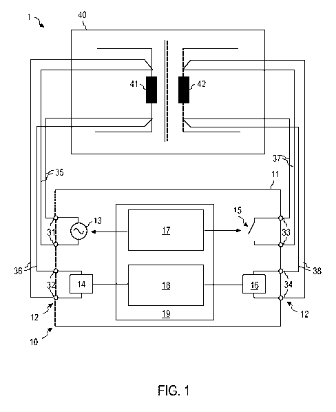
Figure 1 shows a system 1 comprising a transformer test device 10 according to
one
exemplary embodiment.
The system 1 comprises a transformer 40 and the transformer test device 10.
The
transformer test device 10 can be designed as a single apparatus comprising a
housing 11. The transformer test device 10 can comprise an arrangement of a
plurality of apparatuses or devices. In this case, the plurality of
apparatuses or
devices can be controlled by a central controller. The transformer test device
10 can
be designed as a mobile apparatus and, in particular, as a portable apparatus.
If the
transformer test device 10 comprises a plurality of apparatuses, each of the
apparatuses can be designed as a portable apparatus.
The transformer 40 can be a power transformer of an electrical energy supply
device. The transformer 40 can be permanently installed in a power plant or
substation while a transformer test is executed using the transformer test
device 10.
The transformer 40 can be a voltage converter or current converter. The
transformer
40 can be a voltage converter or current converter which operates in
accordance
with an inductive operating principle.
The transformer 40 comprises at least a first winding 41 and a second winding
42. It
is not important whether the first winding 41 is the primary winding and the
second
winding 42 is the secondary winding or vice versa. Similarly, it is not
important
whether the first winding 41 is the high-voltage winding and the second
winding 42 is
the low-voltage winding or vice versa.
The transformer test device 10 comprises a plurality of connections 12, a
source 13
for a test signal which is applied to or impressed on the transformer 40 as a
unit
12
CA 02966456 2017-05-01
Doc. No.: 106-98 CA/PCT Patent
under test during the transformer test, and a controllable switching means 15.
The
controllable switching means 15 can be, for example, a relay, an IGBT or a
FET.
The source 13 can be a current source which is controllable in order to
generate a
direct current and/or an alternating current as test signal. The source 13 can
be
controllable in order to generate alternating currents with several different
frequencies as test signal. The source 13 can be a voltage source which is
controllable in order to generate a DC voltage and/or an AC voltage as test
signal.
The source 13 can be controllable in order to generate AC voltages with
several
different frequencies as test signal. The source 13 can be operable in
different
operating modes, for example as a current source or as a voltage source and/or
as a
source of a temporally constant signal or an alternating signal. The source 13
can
comprise a current measurement device. The source 13 can be designed in order
to
use an output signal from the current measurement device in a control loop for
controlling current. As an alternative or in addition, a current measurement
device
can be connected in series with the source 13.
The transformer test device 10 can comprise further devices, for example one
or
more measurement devices 14, 16 for recording a test response in reaction to
the
test signal. The transformer test device 10 can comprise a control device 17
for
automatically electrically controlling the controllable switching means 15.
The
transformer test device 10 can comprise an evaluation device 18 for evaluating
a test
response of the transformer 40 which is detected using the measurement devices
14, 16. The first measurement device 14 and the second measurement device 16
can each be designed, for example, for a voltage measurement. The first
measurement device 14 and the second measurement device 16 can each be
designed for the purpose of recording other electrical characteristic
variables. The
functions of the control device 17 and/or the evaluation device 18 can be
performed
by a processor 19 or another integrated semiconductor circuit 19.
The source 13 can generate a temporally variable test signal. A frequency of
the test
signal can be variable between several values. The first measurement device 14
and
the second measurement device 16 can be designed to record a test response in
a
time-resolved manner. Measurement values which are recorded by the first
measurement device 14 and the second measurement device 16 can be AID-
converted and further evaluated mathematically, for example in order to
determine
characteristic variables of the transformer for each of several frequencies.
13
CA 02966456 2017-05-01
Doc. No.: 106-98 CA/PCT Patent
The connections 12 comprise output connections 31 which are coupled to the
source
13. The output connections 31 are electrically conductively connected to the
first
winding 41 of the transformer 40 by means of one or more lines 35.
The connections 12 comprise input connections 32, 34 which are connected to
one
or more windings of the transformer by means of one or more lines 36, 38 in
order to
record a test response of the transformer 10. A measurement device 14 can be
connected to the first winding 41, for example, by means of further lines 37
which are
separate from the lines 35. The measurement device 14 can be a voltmeter. A
connection of this kind between the transformer test device 10 and the
transformer
40 allows, for example, measurement in accordance with a so-called four-wire
method. Separately guiding voltage lines from the input connection 32 to the
first
winding 41 can result in a voltage drop of the line 31 between the output
connection
31 and the first winding 41 not corrupting the measurement result.
The transformer test device 10 comprises at least one pair of connections 33
which
can be short-circuited by means of the controllable switching means 15. The
controllable switching means can be a conventional switch, a mechanical-
electrical
switch, a relay, a FET, an IGBT or another component which is suitable for
establishing an electrically conductive connection between the connections 33
depending on a state of the switching means. The conductive path in the
transformer
test device 10 between the connections 33 has an impedance which, at at least
one
frequency or all frequencies with which the test signal is generated by the
source 13,
is smaller than an impedance of the winding 42 to which the pair of
connections 33 is
connected by means of lines 37.
The second winding 42 can also be connected to the connections 12 of the
transformer test device 10 by means of at least four lines 37, 38. The input
connections 34 can comprise a voltage input 34 which can be connected to a
further
voltmeter in order to connect said voltmeter to the second winding 42 of the
transformer 40. Separately guiding the lines 37 and 38 can prevent corruption
of
measurement results by any voltage drop on the line 37 between the pair of
connections 33 and the second winding 42.
The transformer 40 can also comprise more than two windings 41, 42. The
transformer test device 10 can comprise connections for connection to a third
winding of the transformer 40 and any further windings of the transformer 40.
The
transformer test device 10 can comprise connections for connection to any
winding
14
CA 02966456 2017-05-01
Doc. No.: 106-98 CA/PCT Patent
of the transformer 40 for a four-wire measurement. The transformer test device
10
can also comprise at least one second controllable switch 15 in order to short-
circuit
the first winding 41 or further windings of the transformer 40 when said
windings are
connected to the transformer test device 10.
The transformer test device 10 can be designed in order to short-circuit
combinations
of two windings. For example, two of three windings of a transformer can be
short-
circuited at the same time or sequentially in time. Test procedures can also
be run
automatically, in the case of which only one of a plurality of windings of the
transformer is initially short-circuited and then two or more than two
windings are
short-circuited at the same time or sequentially in time. In this case, short-
circuiting
can be performed automatically in each case by a controllable switching means
of
the transformer test device 10.
The transformer test device 10 is designed such that different measurements
can
take place, without the connections 35-38 between the transformer test device
10
and the transformer 40 having to be released and/or connected in some other
way.
The different measurements can be performed without the unit under test having
to
be rewired. The measurements can be carried out in a fully or partially.
automated
manner by the transformer test device 10, that is to say without interaction
of the
user between the measurements.
At least one of the windings of the transformer 40 can be short-circuited by
the
controllable switching means 15 for at least a portion of the measurement.
For example, the transformer test device 10 can perform a transformation
measurement. The source 13 can be operated as an AC voltage source for this
purpose. The switch 15 can be opened. A voltage at the first winding 41 can be
recorded using the first measurement device 14. A voltage at the second
winding 42
can be recorded using the second measurement device 16. The transformation
ratio
can be determined by the transformer test device 10 from a ratio of the
voltages.
As an alternative or in addition, the transformer test device 10 can be
designed in
order to perform a short-circuit impedance measurement. The source 13 can be
operated as an alternating current source for this purpose. The switch 15 can
be
closed. This can be done by a control signal of the control device 17. The
voltage at
the first winding 41 can be recorded using the first measurement device 14. A
current in the second winding 42 can optionally be recorded by an ammeter (not
CA 02966456 2017-05-01
Doc. No.: 106-98 CA/PCT Patent
illustrated in figure 1). The recorded current in the second winding 42 can be
used by
the evaluation device 18 for correction purposes. For example, a fault which
is
produced by a resistance of the lines 37, 38 from the second winding 42 to the
test
device 10 can be at least partially corrected.
As an alternative or in addition, the transformer test device 10 can be
designed in
order to perform a winding resistance measurement. The resistance measurement
can be a static resistance measurement. The winding resistance of the first
winding
41 can be determined. The source 13 can operate as a direct current source for
the
purpose of determining the winding resistance. The voltage at the first
winding 41
can be measured by the first measurement device 14. The direct current can be
impressed until an iron core of the transformer 40 enters saturation. In this
time
interval of the measurement, the controllable switching means 15 can be opened
in
order to more quickly reach the state in which the iron core is saturated. The
controllable switching means 15 can be controlled such that it is closed in
order to
short-circuit the second winding 42 when, after saturation of the transformer
core, a
winding resistance measurement, a short-circuit impedance measurement, a stray
impedance measurement or other measurements are performed. A voltage at the
second winding 42 can respectively also be measured using the second
measurement device 16 and used for the purpose of correcting faults, for
example
on account of line resistances.
As an alternative or in addition, the transformer test device 10 can be
designed in
order to detect a behavior of the transformer 30 at the moment at which the
transformation ratio is switched over. A measurement of this kind is also
called
dynamic resistance measurement. For the purpose of measuring the dynamic
resistance ratio, the controllable switch 15 can be respectively closed at
least when
the switchover process of the transformation ratio takes place. As a result,
the
effects which are recorded at the first winding 14 and which are caused by the
switchover process can be amplified.
Several of said measurements or further measurements which differ therefrom
can
be performed by the transformer test device 10, without the connections
between the
transformer test device 10 and the transformer 40 having to be varied by user
intervention for this purpose. In particular, the several measurements can be
performed without the connection points of the connections 35-38 at the
transformer
and at the connections 12 of the transformer test device 10 having to be
changed.
16
CA 02966456 2017-05-01
Doc. No.: 106-98 CA/PCT Patent
The control device 17 can be designed in order to electrically actuate the
controllable
switching means 15. The control device 17 can switch the controllable
switching
means 15 to a closed state during a portion of a transformer test or during
the entire
transformer test in order to short-circuit the second winding 42.
The transformer test device 10 can be designed in order to sequentially
perform
several different measurements, wherein the measurements and optionally the
order
of said measurements can be established in a user-defined manner. The
transformer
test device 10 can comprise a graphical user interface with which it is
possible to
establish, in a user-defined manner, which measurements are performed.
Depending
on a user input which determines the measurements to be performed, the
controllable switching means 15 and the source 13 can be controlled in a time-
dependent manner such that the selected measurements are performed. It is also
possible for only one single measurement, for example a measurement of the
transformation ratio or a winding resistance measurement or a stray impedance
measurement, to be selected. The transformer test device 10 then switches the
controllable switching means 15 in accordance with the selected measurement.
Figure 2 is an illustration of a system 1 comprising a transformer test device
10
according to a further exemplary embodiment. The transformer test device 10
comprises a graphical user interface 20. The graphical user interface 20 can
be
designed in order to allow measurements which are performed using the
transformer
test device 10 to be established in a user-defined manner. The controllable
switching
means 15 can be switched once or several times during the transformer test.
The
controllable switching means 15 can be automatically switched under the
control of
the control device 17, without a user input or another user action being
required for
this once the transformer test has started.
The transformer test device 10 illustrated in figure 2 also has an ammeter 21
which
is connected in series with the controllable switching means 15. The ammeter
21 can
have an internal resistance which is much smaller than an impedance of the
second
winding 42 to which the connections 33 are connected. An output signal from
the
ammeter 21 can be evaluated by the evaluation device 18, for example in order
to
perform correction of the voltages which are recorded using the measurement
devices 14, 16.
Figure 3 is an illustration of a system 1 comprising a transformer test device
10
according to a further exemplary embodiment. In the transformer test device
10, the
17
CA 02966456 2017-05-01
Doc. No.: 106-98 CA/PCT Patent
measurement devices 14, 16 are configured as voltmeters in order to record a
voltage which is dropped across the first winding 41 and the second winding
42.
Other configurations of the measurement devices 14, 16 can be used.
Figure 4 is a flowchart of a method 50 according to one exemplary embodiment.
The
method 50 can be automatically executed by the transformer test device 10
according to one exemplary embodiment.
A test procedure can be selected at step 51. The test procedure can comprise
one or
more measurements which are performed at the transformer 40. The test
procedure
can be selected in a user-defined manner from amongst a plurality of test
procedures.
The controllable switching means 15 is controlled depending on the selected
test
procedure in step 52. The controllable switching means 15 can be automatically
controlled such that a winding of the transformer 40 is short-circuited during
the
entire test procedure or during a portion of the test procedure. A short-
circuit current
of the winding flows across the transformer test device 10.
The source for the purpose of generating the test signal is controlled in step
53. The
source can be controlled such that it selectively generates a direct current,
a DC
voltage or an AC voltage. Different test signals can also be generated in a
time-
dependent manner.
The actuation of the source and the actuation of the controllable switch can
be
coordinated with one another in respect of time. For example, in a portion of
a test
procedure in which a transformer core is intended to enter saturation, the
controllable switching means can be respectively controlled such that the
second
winding 42 is not short-circuited while the source impresses a direct current
on the
first winding 41.
A test response of the transformer 40 can be automatically evaluated in step
54. The
evaluation can comprise determining a winding resistance in the case of a
static
resistance measurement, determining a stray impedance, determining a stray
inductance, determining a transformation ratio or determining a combination of
two
or more than two of these characteristic variables.
18
CA 02966456 2017-05-01
Doc. No.: 106-98 CA/PCT Patent
The controllable switching means 15 can be switched once or several times
during
the test procedure.
Figure 5 and figure 6 illustrate, by way of example, a control signal Ctrl_s
for
controlling the controllable switching means 15 during a test procedure. The
control
signal can be automatically generated by an integrated semiconductor circuit
of the
transformer test device 10. The control signal can be automatically generated
by an
integrated semiconductor circuit of the transformer test device 10 in
accordance with
a time schedule or depending on an output signal from at least one of the
measurement devices 14, 16, 21 of the transformer test device 10.
Figure 5 illustrates a control signal 60 for actuating the controllable
switching means
in a test procedure which can be performed by the transformer test device 10.
In
a portion 61 of the time period of the test procedure, the control signal 60
has a first
15 value and the controllable switching means 15 is open, so that the
controllable
switching means 15 does not short-circuit the winding 42. At a time during the
test
procedure, the controllable switching means 15 is switched to the closed state
in
order to short-circuit the second winding 42. The control signal 60 is changed
to a
second value for this purpose. In a second portion 62 of the time period of
the test
procedure, the controllable switching means is closed in order to short-
circuit the
second winding 42.
The time at which the controllable switching means 15 is closed can be
established,
for example, by a time schedule or can depend on a condition. For example,
saturation of the transformer core can be monitored. The controllable
switching
means 15 can be closed when the transformer core is completely saturated or
when
the saturation satisfies a prespecified criterion.
Figure 6 illustrates a control signal 65 for actuating the controllable
switching means
15 in a test procedure which can be performed by the transformer test device
10.
The controllable switching means 15 is switched several times to the closed
and the
open state while the test procedure is being performed. For example, in a
portion 66
of the test procedure, the controllable switching means 15 can be respectively
open,
so that the second winding 42 is not short-circuited. In another portion 67 of
the test
procedure, the controllable switching means 15 can be respectively closed, so
that
the second winding 42 is short-circuited.
19
CA 02966456 2017-05-01
Doc. No.: 106-98 CA/PCT Patent
The time at which the controllable switching means 15 is respectively closed
and
opened can be established, for example, by a time schedule or can depend on a
condition as has been described with reference to figure 5.
When the transformer test device 10 is designed in order to short-circuit a
plurality of
windings of the transformer sequentially in time or simultaneously, the
transformer
test device 10 can comprise a plurality of controllable switching means. The
control
signals for the plurality of controllable switching means can be generated in
a
manner coordinated with respect to time in order to run a test procedure in
which a
winding or several windings of the transformer are selectively short-
circuited, without
rewiring having to be performed for this purpose.
Figure 7 is an illustration of a system 1 comprising a transformer test device
10
according to one exemplary embodiment. The transformer 40 is designed such
that
a transformation ratio can be varied. To this end, the transformer 40 can
comprise,
for example, an on-load tap changer 43 which has a first winding 41. The
design and
manner of operation of the on-load tap changer 43 are known to a person
skilled in
the art.
The transformer test device 10 can be designed in order to monitor and
evaluate a
behavior of the transformer 40 during switching over of the on-load tap
changer 43.
The transformer test device 10 can be designed, in particular, for dynamic
resistance
measurement. A winding resistance of the on-load tap changer 43 between the
two
connections of the on-load tap changer can be ascertained during switchover.
To
this end, a direct current or alternating current can be impressed by the
source 13
and a voltage which is dropped across the on-load tap changer 41 can be
recorded
using the measurement device 14.
The controllable switching means 15 is designed in order to selectively short-
circuit
the second winding 42 on the side of the transformer 40 on which an on-load
tap
changer is not provided. The controllable switching means 15 can be
respectively
closed when the on-load tap changer 41 is switched over in order to short-
circuit the
second winding 42. As a result, particularly clear effects can be observed
during the
switchover process. The controllable switching means 15 can be respectively
opened between two processes, so that the second winding 42 is not short-
circuited.
More rapid stabilization of the behavior of the transformer 40 can be achieved
as a
result.
CA 02966456 2017-05-01
Doc. No.: 106-98 CA/PCT Patent
A static resistance measurement in which the resistance of the on-load tap
changer
41 for one or more frequencies is determined can optionally also be performed
for
each switching stage of the on-load tap changer 41.
The transformer test device 10 can comprise an interface in order to perform
switching of the controllable switching means 15 in a manner coordinated with
switchover processes of the on-load tap changer 41. For example, the
transformer
test device 10 can be designed in order to trigger switchover processes of the
on-
load tap changer 41. As an alternative or in addition, a beginning of a
switchover
process can be automatically identified by the transformer test device 10 by
monitoring the voltage across the on-load tap changer and can serve as a
trigger for
automatically switching the controllable switching means 15 to the closed
state.
Figure 8 is a flowchart of a method 70 according to one exemplary embodiment.
The
method 70 can be automatically performed by the transformer test device 10 for
the
purpose of testing a transformer which comprises an on-load tap changer.
The transformer test device 10 is releasably connected to the transformer 40
in step
71.
The on-load tap changer can be moved to a starting position, which can
correspond
to a maximum self-inductance of the on-load tap changer for example, in step
72.
The behavior of the transformer 40 can then be automatically recorded during
each
switchover process of the on-load tap changer 43. A static resistance
measurement
can optionally be performed for each switching stage of the on-load tap
changer 43
in order to ascertain the winding resistance of the on-load tap changer 43. As
an
alternative or in addition, other measurements can take place between the
switchover processes of the on-load tap changer 43.
In step 73, the controllable switching means 15 can be in a state in which the
second
winding 42 is not short-circuited. As a result, more rapid stabilization of
the
transformer can be achieved when a direct current is impressed on the primary
side.
A resistance measurement can take place in step 74. A winding resistance of
the on-
load tap changer 43 can be ascertained.
21
CA 02966456 2017-05-01
Doc. No.: 106-98 CA/PCT Patent
In step 75, the controllable switching means 15 can be actuated such that it
is closed
in order to short-circuit the second winding 42.
The on-load tap changer 43 can be operated in step 76, so that a switchover
process
between different switching stages is triggered. The voltage across the on-
load tap
changer 43 can be measured during the switchover process. In this case, the
source
13 can impress, for example, a direct current. A dynamic resistance can be
ascertained from the recorded voltage during the switchover process.
In step 77, a check can be made to determine whether the last stage of the on-
load
tap changer 43 has been reached. The last stage can be, for example, that
stage in
which the on-load tap changer 43 has the smallest self-inductance. If the last
switching stage has not yet been reached, the method can return to step 73.
The
controllable switching means 15 can be opened in order to not short-circuit
the
second winding 42.
If the last switching stage is reached, the transformer test device can be
disconnected from the transformer in step 78. The results of the transformer
test can
be automatically further evaluated and/or archived by the transformer test
device.
While exemplary embodiments have been described in detail with reference to
the
figures, alternative or additional features can be used in further exemplary
embodiments. While, for example, the use of a transformer test device in
combination with a transformer comprising two windings has been described, the
devices and methods according to exemplary embodiments can also be used for
transformers with three windings or more than three windings.
While the transformer test device can comprise only a controllable switching
means
for short-circuiting only one winding of the transformer in exemplary
embodiments,
the transformer test device can also have two or more than two controllable
switching means for short-circuiting a plurality of turns of the transformer.
The
transformer test device can be designed in order to short-circuit a plurality
of
windings at the same time or sequentially in time.
While the transformer test device can be designed for the purpose of short-
circuiting
a low-voltage side of a transformer in exemplary embodiments, the transformer
test
device can also be designed in order to short-circuit, as an alternative or in
addition
22
CA 02966456 2017-05-01
Doc. No.: 106-98 CA/PCT Patent
to the low-voltage side, the high-voltage side or a tertiary winding of the
transformer
using the controllable switching means.
While a test procedure which involves determining a plurality of
characteristic
variables of the transformer can be automatically performed in exemplary
embodiments, the transformer test device and the method according to exemplary
embodiments can also be used if only one characteristic variable of the
transformer
is measured before a new user input is required.
While the transformer can be installed in a power plant or substation of an
energy
supply network, the transformer test device and the method according to
exemplary
embodiments can also be used in smaller transformers.
Transformer test device, methods and systems according to exemplary
embodiments allow further automation during transformer testing.
23