Note: Descriptions are shown in the official language in which they were submitted.
CA 2966987 2017-05-12
APPARATUS AND METHOD FOR GENERATING BANDWIDTH
EXTENSION SIGNAL
This application is a divisional of Canadian patent application no. 2,840,732,
filed
July 2, 2012, and claiming priority to provisional U.S. patent application no.
61/503,241,
filed June 30, 2011. =
Technical Field
Apparatuses and methods consistent with exemplary embodiments relates to
audio encoding and decoding, and more particularly, to an apparatus and a
method for
generating a bandwidth extended signal, capable of reducing metal-like noise
of a
bandwidth extended signal for a high-frequency band, an apparatus and a method
for
encoding an audio signal, an apparatus and a method for decoding an audio
signal and
a terminal, which employs the same.
Background
A signal corresponding to a high-frequency band is less sensitive to a fine
structure of frequencies in comparison to a signal corresponding to a low-
frequency
band. Accordingly, in order to increase coding efficiency to cope with
restrictions of
allowable bits when an audio signal is encoded, a signal corresponding to a
low-frequency band is encoded by allocating a relatively large number of bits
and a
signal corresponding to a high-frequency band is encoded by allocating a
relatively
small number of bits.
The above-described method is used in spectral band replication (SBR). In
SBR, a lower band of a spectrum, e.g., a low-frequency band or a core band, is
encoded and an upper band, e.g., a high-frequency band, is encoded by using
parameters, e.g., an envelope. SBR uses correlations between lower and upper
bands
such that characteristics of the lower band are extracted to predict the upper
band.
1
CA 2966987 2017-05-12
In SBR, an improved method for generating a bandwidth extended signal for a
high-frequency band is required.
Description of Drawings
FIG. 1 shows a block diagram of an audio encoding apparatus according to an
exemplary embodiment;
FIG. 2 shows a block diagram of an example of a frequency domain (FD)
encoding unit illustrated in FIG. 1;
FIG. 3 shows a block diagram of another example of the FD encoding unit
illustrated in FIG. 1;
1c) FIG. 4 shows a block diagram of an anti-sparseness processing unit
according to
according to an exemplary embodiment;
FIG. 5 shows a block diagram of an FD high-frequency extension encoding unit
according to an exemplary embodiment;
FIGS. 6A and 6B are graphs showing a region where extension encoding is
performed by an FD encoding module illustrated in FIG. 1;
FIG. 7 shows a block diagram of an audio encoding apparatus according to
another exemplary embodiment;
FIG. 8 shows a block diagram of an audio encoding apparatus according to
another exemplary embodiment;
FIG. 9 shows a block diagram of an audio decoding apparatus according to an
exemplary embodiment;
FIG. 10 shows a block diagram of an example of an FD decoding unit illustrated
in FIG. 9;
2
CA 2966987 2017-05-12
FIG. 11 shows a block diagram of an example of an FD high-frequency extension
decoding unit illustrated in FIG. 10;
FIG. 12 shows a block diagram of an audio decoding apparatus according to
another exemplary embodiment;
FIG. 13 shows a block diagram of an audio decoding apparatus according to
another exemplary embodiment;
FIG. 14 shows a diagram for describing a codebook sharing method according to
an exemplary embodiment; and
FIG. 15 shows a diagram for describing a coding mode signaling method
according to an exemplary embodiment.
Detailed Description of Example Embodiments
Technical Problem
Aspects of one or more exemplary embodiments provide an apparatus and a
method for generating a bandwidth extended signal, capable of reducing metal-
like of a
bandwidth extended signal for a high-frequency band, an apparatus and a method
for
encoding an audio signal, an apparatus and a method for decoding an audio
signal and
a terminal, which employs the same.
=
Technical Solution
According to an aspect of one or more exemplary embodiments, there is
provided a method of generating a bandwidth extended signal, the method
including
performing anti-sparseness processing on a low-frequency spectrum; and
performing
high-frequency extension encoding in the frequency domain on the low-frequency
spectrum on which the anti-sparseness processing is performed.
According to another aspect of one or more exemplary embodiments, there is
provided an apparatus for generating a bandwidth extended signal, the
apparatus
3
CA 2966987 2017-05-12
including an anti-sparseness processing unit to perform anti-sparseness
processing on
a low-frequency spectrum; and a frequency domain high-frequency extension
decoding
unit to perform high-frequency extension encoding in the frequency domain on
the
low-frequency spectrum on which the anti-sparseness processing is performed.
Advantageous Effects
Metallic noises caused by emphasis of tone components may be reduced by
performing an anti-sparseness processing on a signal used for extension of a
high-frequency band, which results in the reduction of spectrum holes
generated in the
high-frequency extended signal.
o Mode for Invention
While exemplary embodiments of the present inventive concept are susceptible
to various modifications and alternative forms, specific embodiments thereof
are shown
by way of example in the drawings and will herein be described in detail. It
should be
understood, however, that there is no intent to limit exemplary embodiments to
the
particular forms disclosed, but conversely, exemplary embodiments are to cover
all
modifications, equivalents, and alternatives falling within the scope of the
claims. In the
following description of the present inventive concept, a detailed description
of known
functions and configurations incorporated herein will be omitted when it may
make the
subject matter of the present inventive concept unclear.
It will be understood that, although the terms first, second, etc. may be used
herein to describe various elements, these elements should not be limited by
these
terms. These terms are only used to distinguish one element from another.
The terminology used herein is for the purpose of describing particular
embodiments and is not intended to limit the inventive concept. Although
general
terms are used as long as possible in consideration of the functions of the
present
inventive concept their meanings may vary according to intentions of one of
ordinary
skill in the art, precedents, or the appearance of new technologies. Also, in
particular
cases, terms can be arbitrarily selected by the applicant and, in this case,
their
4
CA 2966987 2017-05-12
meanings will be described in detail in the detailed description of the
inventive concept.
Accordingly, definitions of the terms should be understood on the basis of the
entire
description of the present specification.
As used herein, the singular forms "a", "an", and "the" are intended to
include the
plural forms as well, unless the context clearly indicates otherwise. It will
be further
understood that the terms "comprises" and/or "comprising," when used in this
specification, specify the presence of stated features, integers, steps,
operations,
elements, and/or components, but do not preclude the presence or addition of
one or
more other features, integers, steps, operations, elements, components, and/or
groups
thereof.
Hereinafter, the present inventive concept will be described in detail by
explaining embodiments of the inventive concept with reference to the attached
drawings. In the drawings, like reference numerals denote like elements and
the sizes
or thicknesses of elements may be exaggerated for clarity of explanation.
FIG. 1 is a block diagram of an audio encoding apparatus 100 according to an
exemplary embodiment. The audio encoding apparatus 100 illustrated in FIG. 1
may
form a multimedia device and may be, but not limited to, a voice communication
device
such as a phone or a mobile phone, a broadcasting or music device such as a TV
or an
MP3 player, or a combined device of the voice communication device and the
broadcasting or music device. Also, the audio encoding apparatus 100 may be
used
as a converter included in a client device or a server, or disposed between
the client
device and the server.
The audio encoding apparatus 100 illustrated in FIG. 1 may include a coding
mode determination unit 110, a switching unit 130, a code excited linear
prediction
(CELP) encoding module 150, and a frequency domain (FD) encoding module 170.
The CELP encoding module 150 may include a CELP encoding unit 151 and a time
domain (TD) extension encoding unit 153, and the FD encoding module 170 may
include a transformation unit 171 and an FD encoding unit 173. The above
elements
5
CA 2966987 2017-05-12
may be integrated into at least one module and may be implemented by at least
one
processor (not shown).
Referring to FIG. 1, the coding mode determination unit 110 may determine a
coding mode of an input signal with reference to signal characteristics.
According to
the signal characteristics, the coding mode determination unit 110 may
determine
whether a current frame is in a speech mode or a music mode, and may also
determine
whether a coding mode efficient for the current frame is a TD mode or an FD
mode. In
this case, the signal characteristics may be obtained by using, but are not
limited to,
short-term characteristics of a frame or long term characteristics of a
plurality of frames.
The coding mode determination unit 110 may determine a CELP mode if the signal
characteristics correspond. to a speech mode or a TD mode, and may determine
an FD
mode if the signal characteristics correspond to a music mode or an FD mode.
According to an embodiment, the input signal of the coding mode determination
unit 110 may be a signal that is down-sampled by a down sampling unit (not
shown).
For example, the input signal may be a signal having a sampling rate of 12.8
kHz or 16
kHz, which is obtained by re-sampling or down-sampling a signal having a
sampling
rate of 32 kHz or 48 kHz. Here, a signal having a sampling rate of 32 kHz is a
super
wide band (SWB) signal and may be referred to as a full band (FB) signal, and
a signal
having a sampling rate of 16 kHz may be referred to as a wide band (WB)
signal.
According to another embodiment, the coding mode determination unit 110 may
perform the re-sampling or down-sampling operation.
As such, the coding mode determination unit 110 may determine a coding mode
of the re-sampled or down-sampled signal.
Information regarding the coding mode determined by the coding mode
determination unit 110 may be provided to the switching unit 130 and may be
included
in a bitstream in units of frames so as to be stored or transmitted.
According to the information regarding the coding mode, which is provided from
the coding mode determination unit 110, the switching unit 130 may provide the
input
6
CA 2966987 2017-05-12
signal to the CELP encoding module 150 or the FD encoding module 170. Here,
the
input signal may be a re-sampled or down-sampled signal and may be a low-
frequency
signal having a sampling rate of 12.8 kHz or 16 kHz. Specifically, the
switching unit
130 provides the input signal to the CELP encoding module 150 if the coding
mode is a
CELP mode, and provides the input signal to the FD encoding module 170 if the
coding
mode is an FD mode.
The CELP encoding module 150 may operate if the coding mode is a CELP
mode, and the CELP encoding unit 151 may perform CELP encoding on the input
signal.
According to an embodiment, the CELP encoding unit 151 may extract an
excitation
signal from the re-sampled or down-sampled signal, and may quantize the
extracted
excitation signal in consideration of each of a filtered adaptive code vector
(i.e., an
adaptive codebook contribution) and a filtered fixed code vector (i.e., a
fixed or
innovation codebook contribution) corresponding to pitch information.
According to
another embodiment, the CELP encoding unit 151 may extract linear prediction
coefficients (LPCs), may quantize the extracted LPCs, may extract an
excitation signal
by using the quantized LPCs, and may quantize the extracted excitation signal
in
consideration of each of a filtered adaptive code vector (i.e., an adaptive
codebook
contribution) and a filtered fixed code vector (i.e., a fixed or innovation
codebook
contribution) corresponding to pitch information.
Meanwhile, the CELP encoding unit 151 may apply different coding modes
according to the signal characteristics. The applied coding modes may include,
but are
not limited to, a voiced coding mode, an unvoiced coding mode, a transient
coding
mode, and a generic coding mode.
The low-frequency, excitation signal obtained by the encoding of the CELP
encoding unit 151, i.e., CELP information, may be provided to the TD extension
encoding unit 153 and may be included in the bitstream so as to be stored or
transmitted.
In the CELP encoding module 150, the TD extension encoding unit 153 may
perform high-frequency extension encoding by folding or replicating the low-
frequency
7
CA 2966987 2017-05-12
excitation signal provided from the CELP encoding unit 151. High-frequency
extension
information obtained by the extension encoding of the TD extension encoding
unit 153
may be included in the bitstream so as to be stored or transmitted. The TD
extension
encoding unit 153 quantizes LPCs corresponding to a high-frequency band of the
input
signal. In this case, the TD extension encoding unit 153 may extract LPCs of a
high-frequency band of the input signal and may quantize the extracted LPCs.
Also,
the TD extension encoding unit 153 may generate LPCs of the high-frequency
band of
the input signal by using the low-frequency excitation signal of the input
signal. Here,
the LPCs of the high-frequency band may be used to represent envelope
information of
the high-frequency band.
Meanwhile, the FD encoding module 170 may operate if the coding mode is an
FD mode, and the transformation unit 171 may transform the re-sampled or
down-sampled signal from' the time domain to the frequency domain. In this
case, the
transformation unit 171 may perform, but is not limited to, modified discrete
cosine
transformation (MDCT). In the FD encoding module 170, the FD encoding unit 173
may perform FD encoding on the re-sampled or down-sampled spectrum provided
from
the transformation unit 171. The FD encoding may be performed by using, but is
not
limited to, an algorithm applied to the Advanced Audio Codec (AAC). FD
information
obtained by the FD encoding of the FD encoding unit 173 may be included in the
2C, bitstream so as to be stored or transmitted. Meanwhile, if coding modes
of neighboring
frames are changed from a CELP mode into an FD mode, prediction data may be
further included in the bitstream obtained due to the FD encoding of the FD
encoding
unit 173. Specifically, since, if encoding based on a CELP mode is performed
on an
Nth frame and encoding based on an FD mode is performed on an (N+1)th frame,
the
(N+1)th frame may not be decoded by using only a result of the encoding based
on an
FD mode, prediction data to be referred to in a decoding process needs to be
additionally included.
In the audio encoding apparatus 100 illustrated in FIG. 1, two types of a
bitstream may be generated according to the coding mode determined by the
coding
8
CA 2966987 2017-05-12
mode determination unit 110. Here, the bitstream may include a header and a
payload.
Specifically, if the coding mode is a CELP mode, information regarding the
coding mode may be included in the header, and CELP information and TD
extension
information may be included in the payload. Otherwise, if the coding mode is
an FD
mode, information regarding the coding mode may be included in the header, and
FD
information and prediction data may be included in the payload. Here, the FD
information may include FD high-frequency extension information.
Meanwhile, in order to be prepared for a case when a frame error occurs, a
header of each bitstream may further include information regarding a coding
mode of a
previous frame. For example, if a coding mode of a current frame is determined
as an
FD mode, the header of the bitstream may further include information regarding
a
coding mode of a previous frame.
The audio encoding apparatus 100 illustrated in FIG. 1 may be switched to a
CELP mode or an FD mode according to signal characteristics and thus may
efficiently
perform adaptive encoding with respect to the signal characteristics.
Meanwhile, the
switching structure illustrated in FIG. 1 may be applied to a high bit rate
environment.
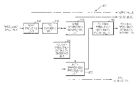
FIG. 2 is a block diagram of an example of the FD encoding unit 173
illustrated in
FIG. 1.
Referring to FIG. 2, an FD encoding unit 200 may include a norm encoding unit
210, a factorial pulse coding (FPC) encoding unit 230, an FD low-frequency
extension
encoding unit 240, a noise information generation unit 250, an anti-sparseness
processing unit 270, and an FD high-frequency extension encoding unit 290.
The norm encoding unit 210 estimates or calculates a norm value of each
frequency band, e.g., each subband, of a frequency spectrum provided from the
transformation unit 171 illustrated in FIG. 1, and quantizes the estimated or
calculated
norm value. Here, the norm value may refer to an average of spectral energy
calculated in units of subbands, and may also be referred to as power. The
norm
9
CA 2966987 2017-05-12
value may be used to normalize the frequency spectrum in units of subbands.
Also,
with respect to a total number of bits according to a target bit rate, the
norm encoding
unit 210 may calculate a masking threshold value by using the norm value of
each
subband, and may determine the number of bits to be allocated to perform
perceptual
encoding on each subband by using the masking threshold value. Here, the
number of
bits may be determined in units of an integer or a decimal. The norm value
quantized
by the norm encoding unit 210 may be provided to the FPC encoding unit 230,
and may
be included in a bitstream so as to be stored or transmitted.
The FPC encoding unit 230 may quantize the normalized spectrum by using the
io number of bits allocated to each subband, and may perform FPC
encoding on a result
of the quantization. Due to the FPC encoding, information such as the
position,
amplitude, and sign of a pulse may be represented in the form of a factorial
within a
range of the number of allocated bits. FPC information obtained by the FPC
encoding
unit 230 may be included in the bitstream so as to be stored or transmitted.
15
The noise information generation unit 250 may generate noise information,
i.e., a
noise level, in units of subbands according to a result of the FPC encoding.
Specifically, due to lack of bits, the frequency spectrum encoded by the FPC
encoding
unit 230 may have an unencoded part, i.e., a hole, in units of subbands.
According to
an embodiment, the noise level may be generated by using an average of levels
of
20 unencoded spectral coefficients. The noise level generated by the
noise information
generation unit 250 may be included in the bitstream so as to be stored or
transmitted.
Also, the noise level may be generated in units of frames.
The anti-sparseness processing unit 270 determines the location and the
amplitude of noise to be added from a reconstructed low-frequency spectrum.
The
25 anti-sparseness processing unit 270 performs anti-sparseness
processing according to
the determined location and the amplitude of noise on the frequency spectrum
on which
noise filling has been performed by using the noise level, and provides the
resultant
spectrum to the FD high-frequency extension encoding unit 290. According to an
embodiment, the reconstructed low-frequency spectrum may refer to a spectrum
CA 2966987 2017-05-12
obtained by extending a low-frequency band from a result of the FPC decoding,
performing noise filling, and then performing anti-sparseness processing.
The FD high-frequency extension encoding unit 290 may perform high-frequency
extension encoding by using the low-frequency spectrum provided from the
anti-sparseness processing unit 270. In this case, an original high-frequency
spectrum
may also be provided to the FD high-frequency extension encoding unit 290.
According to an embodiment, the FD high-frequency extension encoding unit 290
may
obtain an extended high-frequency spectrum by folding or replicating the low-
frequency
spectrum, and extracts energy in units of subbands with respect to the
original
c, high-frequency spectrum, adjusts the extracted energy, and quantizes the
adjusted
energy.
According to an embodiment, energy may be adjusted to correspond to a ratio
between a first tonality calculated in units of subbands with respect to an
original
high-frequency spectrum, and a second tonality calculated in units of subbands
with
respect to a high-frequency excitation signal extended from the low-frequency
spectrum.
Alternatively, according to another embodiment, energy may be adjusted to
correspond
to a ratio between a first noisiness factor calculated by using the first
tonality, and a
second noisiness factor calculated by using the second tonality. Here, each of
the first
and second noisiness factors represents the amount of noise components in a
signal.
As such, if the second tonality is greater than the first tonality, or if the
first noisiness
factor is greater than the second noisiness factor, noise increase in a
reconstruction
process may be prevented by reducing the energy of a corresponding subband. In
an
opposite case, the energy of a corresponding subband may be increased.
Also, in order to perform vector quantization by collecting energy
information, the
FD high-frequency extension encoding unit 290 may simulate a method of
generating
an excitation signal in a predetermined frequency band, and may control energy
when
characteristics of the excitation signal according to a result of the
simulation is different
from characteristics of the.original signal in the predetermined frequency
band. In this
case, the characteristics of the excitation signal according to the result of
the simulation
and the characteristics of the original signal may include at least one of a
tonality and a
11
CA 2966987 2017-05-12
noisiness factor, but are not limited thereto. Thus, it is possible to prevent
noise from
increasing when a decoding side decodes actual energy.
Meanwhile, energy may be quantized by using, but is not limited to, a
multistage
vector quantization (MSVQ) method. Specifically, the FD high-frequency
extension
encoding unit 290 may collect and perform vector quantization on the energy of
odd-number subbands from among a predetermined number of subbands in a current
stage, may obtain prediction errors of even-number subbands by using a result
of
performing vector quantization on the odd-number subbands, and may perform
vector
quantization on the obtained prediction errors in a next stage. Meanwhile, a
case
opposite to the above is also possible. That is, the FD high-frequency
extension
encoding unit 290 obtains a prediction error of an (n+1)th subband by using
results of
performing vector quantization on an nth subband and an (n+2)th subband.
Meanwhile, when vector quantization is performed on energy, a weight according
to significance of each energy vector or a signal obtained by subtracting an
average
value from each energy vector may be calculated. In this case, the weight
according to
significance may be calculated to maximize the quality of a synthesized sound.
If the
weight according to significance is calculated, a quantization index optimized
for an
energy vector may be calculated by using a weighted mean square error (WMSE)
to
which the weight is applied.
The FD high-frequency extension encoding unit 290 may use a multimode
bandwidth extension method for generating various excitation signals according
to
characteristics of a high-frequency signal.
The multimode bandwidth extension
method may provide, for example, a transient mode, a normal mode, a harmonic
mode,
or a noise mode according to characteristics of a high-frequency signal. Since
the FD
high-frequency extension encoding unit 290 operates with respect to a
stationary frame,
an excitation signal of each frame may be generated by using a normal mode, a
harmonic mode, or a noise mode according to characteristics of a high-
frequency
signal.
12
CA 2966987 2017-05-12
Also, the FD high-frequency extension encoding unit 290 may generate signals
of different high-frequency bands according to a bit rate. That is, a high-
frequency
band on which the FD high-frequency extension encoding unit 290 performs
extension
encoding may be set differently according to a bit rate. For example, the FD
high-frequency extension encoding unit 290 may perform extension encoding on a
frequency band of about 6.4 to 14.4 kHz at a bit rate of 16 kbps, and may
perform
extension encoding on a frequency band of about 8 to 16 kHz at a bit rate
greater than
16 kbps.
For this, the FD high-frequency extension encoding unit 290 may perform energy
io quantization by sharing the same codebook with respect to different bit
rates.
Meanwhile, in the FD encoding unit 200, if a stationary frame is input, the
norm
encoding unit 210, the FPC encoding unit 230, the noise information generation
unit 250,
the anti-sparseness processing unit 270, and the FD extension encoding unit
290 may
operate. In particular, the anti-sparseness processing unit 270 may operate
with
respect to a normal mode of a stationary frame. Meanwhile, if a non-stationary
frame,
i.e., a transient frame, is input, the noise information generation unit 250,
the
anti-sparseness processing unit 270, and the FD extension encoding unit 290 do
not
operate. In this case, compared to a case when a stationary frame is input,
the FPC
encoding unit 230 may increase an upper frequency band allocated to perform
FPC, i.e.,
a core frequency band Fcore, to a higher frequency band Fend.
FIG. 3 is a block diagram of another example of the FD encoding unit
illustrated
in FIG. 1.
Referring to FIG. 3, the FD encoding unit 300 may include a norm encoding unit
310, an FPC encoding unit 330, an FD low-frequency extension encoding unit
340, an
anti-sparseness processing unit 370, and an FD high-frequency extension
encoding unit
390. Here, operations of the norm encoding unit 310, the FPC encoding unit
330, and
the FD high-frequency extension encoding unit 390 are substantially the same
as those
of the norm encoding unit 210, the FPC encoding unit 230, and the FD high-
frequency
13
CA 2966987 2017-05-12
extension encoding unit 290 illustrated in FIG. 2, and thus detailed
descriptions thereof
are not provided here.
A difference from FIG. 2 is that the anti-sparseness processing unit 370 does
not
use an additional noise level and uses a norm value obtained in units of
subbands from
the norm encoding unit 310. That is, the anti-sparseness processing unit 370
determines the location and the amplitude of noise to be added in a
reconstructed
low-frequency spectrum, performs anti-sparseness processing according to the
determined location and the amplitude of noise on the frequency spectrum on
which
noise filling has been performed by using the norm value, and provides the
resultant
spectrum to the FD high-frequency extension encoding unit 390. Specifically,
with
respect to a subband including a part that is inversely quantized to 0, a
noise
component may be generated and the energy of the noise component may be
adjusted
by using a ratio between the energy of the noise component and an inversely
quantized
norm value, i.e., spectral energy. According to another embodiment, with
respect to a
subband including a part that is inversely quantized to 0, a noise component
may be
generated and adjusted in such a way that an average energy of the noise
component
is 1.
FIG. 4 is a block diagram of an anti-sparseness processing unit according to
an
exemplary embodiment.
Referring to FIG. 4, the anti-sparseness processing unit 400 may include a
reconstructed spectrum generation unit 410, a noise location determination
unit 430, a
noise amplitude determination unit 450, and a noise adding unit 470
The reconstructed spectrum generation unit 410 generates a reconstructed
low-frequency spectrum by using FPC information provided from the FPC encoding
unit
230 or 330 illustrated in FIG. 2 or 3 and noise filling information such as a
noise level or
a norm value.
In this case, if Fcore and Ffpc are different, the reconstructed
low-frequency spectrum may be generated by additionally performing FD low-
frequency
extension encoding.
14
CA 2966987 2017-05-12
The noise location determination unit 430 may determine a spectrum restored to
0 in the reconstructed low-frequency spectrum as the location of noise.
According to
another embodiment, the location of noise to be added may be determined among
spectrums restored to 0, in consideration of the amplitude of a neighboring
spectrum.
For example, if the amplitude of a neighboring spectrum of a spectrum restored
to 0 is
equal to or greater than a predetermined value, the spectrum restored to 0 may
be
determined as the location of noise. Here, the predetermined value may be
previously
set as an optimal value that is set through simulation or experiment to
minimize
information loss of a neighboring spectrum of a spectrum restored to 0.
The noise amplitude determination unit 450 may determine the amplitude of
noise to
be added to the determined location of noise. According to an embodiment, the
amplitude
of noise may be determined based on a noise level. For example, the amplitude
of noise
may be determined by changing a noise level by a predetermined ratio.
Specifically, the
amplitude of noise may be determined as, but is not limited to, (0.5 x noise
level).
According to another embodiment, the amplitude of noise may be determined by
adaptively
changing a noise level in consideration of the amplitude of a neighboring
spectrum at the
determined location of noise. If the amplitude of a neighboring spectrum is
smaller than
the amplitude of noise to be added, the amplitude of the noise may be changed
to be less
than the amplitude of the neighboring spectrum.
The noise adding unit 470 may add noise based on the determined location and
the
amplitude of noise by using random noise. According to an embodiment, a random
sign
may be applied. The amplitude of noise may have a fixed value and the sign of
the value
may be changed according to whether a random signal generated by using a
random seed
has an odd or even value. For example, a + sign may be given if the random
signal has an
even value, and a ¨ sign may be given if the random signal has an odd value.
The
low-frequency spectrum to which noise is added by the noise adding unit 470 is
provided to
the FD high-frequency extension encoding unit 290 illustrated in FIG. 2. The
low-frequency
spectrum which is provided to the FD high-frequency extension encoding unit
290 may
indicate a core decoded signal which is obtained by performing a noise filling
processing, a
CA 2966987 2017-05-12
low-frequency band extension and an anti-sparseness processing, on a low-
frequency
spectrum obtained from an FPC decoding.
FIG. 5 is a block diagram of an FD high-frequency extension encoding unit
according to an exemplary embodiment.
Referring to FIG. 5, the FD high-frequency extension encoding unit 500 may
include a spectrum copying unit 510, a first tonality calculation unit 520, a
second
tonality calculation unit 530, an excitation signal generating method
determination unit
540, an energy adjusting unit 550, and an energy quantization unit 560.
Meanwhile, if
an encoding apparatus requires a reconstructed high-frequency spectrum, a
reconstructed high-frequency spectrum generating module 570 may be further
included.
The reconstructed high-frequency spectrum generating module 570 may include a
high-frequency excitation signal generation unit 571 and a high-frequency
spectrum
generation unit 573. In particular, if the FD encoding unit 173 illustrated in
FIG. 1 uses
a transformation method, e.g., MDCT, capable of allowing restoration by
performing an
overlap¨add method on a previous frame, and if a CELP mode and an FD mode are
switched between frames, the reconstructed high-frequency spectrum generating
module 570 needs to be added.
The spectrum copying unit 510 may fold or replicate the low-frequency spectrum
provided from the anti-sparseness processing unit 270 or 370 illustrated in
FIG. 2 or 3
so as to extend the low-frequency spectrum to a high-frequency band. For
example, a
high-frequency band of 8 to 16 kHz may be extended by using a low-frequency
spectrum of 0 to 8 kHz. According to an embodiment, instead of the low-
frequency
spectrum provided from the anti-sparseness processing unit 270 or 370, an
original
low-frequency spectrum may be extended to a high-frequency band by folding or
replicating the original low-frequency spectrum.
The first tonality calculation unit 520 calculates a first tonality in units
of
predetermined subbands with respect to an original high-frequency spectrum.
16
CA 2966987 2017-05-12
The second tonality calculation unit 530 calculates a second tonality in units
of
subbands with respect to the high-frequency spectrum extended by using the
low-frequency spectrum by the spectrum copying unit 510.
Each of the first and second tonalities may be calculated by using spectral
flatness based on a ratio between an average amplitude and a maximum amplitude
of a
spectrum of a subband. Specifically, the spectral flatness may be calculated
by using
correlations between a geometrical average and an arithmetical average of a
frequency
spectrum. That is, the first and second tonalities represent whether a
spectrum has
peaky or flat characteristics. The first and second tonality calculation units
520 and
ic 530 may operate by using the same method in units of the same subband.
The excitation signal generating method determination unit 540 may determine a
method of generating a high-frequency excitation signal by comparing the first
and
second tonalities. The method of generating a high-frequency excitation signal
may be
determined by using the high-frequency spectrum generated by modifying the
low-frequency spectrum and an adaptive weight of random noise. In this case, a
value
corresponding to the adaptive weight may be excitation signal type
information, and the
excitation signal type information may be included in a bitstream so as to be
stored or
transmitted. According to an embodiment, the excitation signal type
information may
be formed in 2 bits. Here, the 2 bits may be formed in four steps with
reference to a
weight to be applied to random noise. The excitation signal type information
may be
transmitted once for each frame. Also, a plurality of subbands may form one
group
and the excitation signal type information may be defined in each group and
may be
transmitted for each group.
According to an embodiment, the excitation signal generating method
determination unit 540 may determine the method of generating a high-frequency
excitation signal in consideration of only characteristics of an original high-
frequency
signal. Specifically, the method of generating the excitation signal may be
determined
by identifying a region including an average of first tonalities calculated in
units of
subbands and according to a region corresponding to the value of a first
tonality with
reference to the number of pieces of the excitation signal type information.
According
17
CA 2966987 2017-05-12
to the above method, if the value of a tonality is high, i.e., if a spectrum
has peaky
characteristics, a weight to be applied to random noise may be set to be
small.
According to another embodiment, the excitation signal generating method
determination unit 540 may determine the method of generating the high-
frequency
excitation signal in consideration of both characteristics of the original
high-frequency
signal and characteristics of a high-frequency signal to be generated by
performing
band extension. For example, if the characteristics of the original high-
frequency
signal and the characteristics of the high-frequency signal to be generated by
performing band extension are similar, a weight of random noise may be set to
be small.
Otherwise, if the characteristics of the original high-frequency signal and
the
characteristics of the high-frequency signal to be generated by performing
band
extension are different, a weight of random noise may be set to be large.
Meanwhile, it
may be set with reference to an average of differences between the first and
second
tonalities for each subband. If the average of differences between the first
and second
tonalities for each subband is large, a weight of random noise may be set to
be large.
Otherwise, if the average of differences between the first and second
tonalities for each
subband is small, a weight of random noise may be set to be small. Meanwhile,
if the
excitation signal type information is transmitted for each group, the average
of
differences between the first and second tonalities for each subband is
calculated by
using an average of subbands included in one group.
The energy adjusting unit 550 may calculate energy in units of subbands with
respect to the original high-frequency spectrum, and adjusts the energy by
using the
first and second tonalities. For example, if the first tonality is large and
the second
tonality is small, i.e., if the original high-frequency spectrum is peaky and
an output
spectrum of the anti-sparseness processing unit 270 or 370 is flat, the energy
is
adjusted based on a ratio of the first and second tonalities.
The energy quantization unit 560 may perform vector quantization on the
adjusted energy and may include in the bitstream a quantization index
generated due to
the vector quantization so as to store or transmit the bitstream.
18
CA 2966987 2017-05-12
Meanwhile, in the reconstructed high-frequency spectrum generating module 570,
operations of the high-frequency excitation signal generation unit 571 and the
high-frequency spectrum generation unit 573 are substantially the same as
those of a
high-frequency excitation signal generation unit 1130 and a high-frequency
spectrum
generation unit 1170 illustrated in FIG. 11, and thus detailed descriptions
thereof will not
be provided here.
FIGS. 6A and 6B are graphs showing a region where extension encoding is
performed by the FD encoding module 170 illustrated in FIG. 1. FIG. 6A shows a
case
when an upper frequency band Ffpc on which FPC has been actually performed is
the
same as a low-frequency band allocated to perform FPC, i.e., a core frequency
band
Fcore. In this case, FPC and noise filling are performed on a low-frequency
band to
Fcore, and extension encoding is performed by using a signal of the low-
frequency
band on a high-frequency band corresponding to Fend-Fcore. Here, Fend may be a
maximum frequency that is obtainable due to high-frequency extension.
Meanwhile, FIG. 6B shows a case when an upper frequency band Ffpc on which
FPC has been actually performed is smaller than a core frequency band Fcore.
FPC
and noise filling are performed on a low-frequency band corresponding to Ffpc,
extension encoding is performed on a low-frequency band corresponding to Fcore-
Ffpc
by using a signal of the low-frequency band on which FPC and noise filling
have been
performed, and extension encoding is performed on a high-frequency band
corresponding to Fend-Fcore by using a signal of the whole low-frequency band.
Likewise, Fend may be a maximum frequency that is obtainable due to high-
frequency
extension.
Here, Fcore and Fend may be variably set according to a bit rate. For example,
according to a bit rate, Fcore may be, but is not limited to, 6.4 kHz, 8 kHz,
or 9.6 kHz,
and Fend may be extended to, but is not limited to, 14 kHz, 14.4 kHz, or 16
kHz.
Meanwhile, the upper frequency band Ffpc on which FPC has been actually
performed
corresponds to a frequency band on which noise filling is performed.
19
CA 2966987 2017-05-12
FIG. 7 is a block diagram of an audio encoding apparatus according to another
exemplary embodiment.
The audio encoding apparatus 700 illustrated in FIG. 7 may include a coding
mode determination unit 710, an LPC encoding unit 705, a switching unit 730, a
CELP
encoding module 750, and an audio encoding module 770. The CELP encoding
module 750 may include a CELP encoding unit 751 and a TO extension encoding
unit
753, and the audio encoding module 770 may include an audio encoding unit 771
and
an FD extension encoding unit 773. The above elements may be integrated into
at
least one module and may be driven by at least one processor (not shown).
Referring to FIG. 7, the LPC encoding unit 705 may extract LPCs from an input
signal and may quantize the extracted LPCs. For example, the LPC encoding unit
705
may quantize the LPCs by using, but is not limited to, a trellis coded
quantization (TCQ)
method, a multistage vector quantization (MSVQ) method, or a lattice vector
quantization (LVQ) method. The LPCs quantized by the LPC encoding unit 705 may
be included in a bitstream so as to be stored or transmitted.
Specifically, the LPC encoding unit 705 may extract LPCs from a signal having
a
sampling rate of 12.8 kHz or 16 kHz, which is obtained by re-sampling or
down-sampling a signal having a sampling rate of 32 kHz or 48 kHz.
Like the coding mode determination unit 110 illustrated in FIG. 1, the coding
mode determination unit 710 may determine a coding mode of the input signal
with
reference to signal characteristics. According to the signal characteristics,
the coding
mode determination unit 710 may determine whether a current frame is in a
speech
mode or a music mode, and may also determine whether a coding mode efficient
for the
current frame is a TD mode or an FD mode.
The input signal of the coding mode determination unit 710 may be a signal
that
is down-sampled by a down sampling unit (not shown). For example, the input
signal
may be a signal having a sampling rate of 12.8 kHz or 16 kHz, which is
obtained by
re-sampling or down-sampling a signal having a sampling rate of 32 kHz or 48
kHz.
CA 2966987 2017-05-12
Here, a signal having a sampling rate of 32 kHz is an SWB signal and may be
referred
to as an FB signal, and a signal having a sampling rate of 16 kHz may be
referred to as
a WB signal.
According to another embodiment, the coding mode determination unit 710 may
perform the re-sampling or down-sampling operation.
As such, the coding mode determination unit 710 may determine a coding mode
of the re-sampled or down-sampled signal.
[Information regarding the coding mode determined by the coding mode
determination unit 710 may be provided to the switching unit 730 and may be
included
-10 in a bitstream in units of frames so as to be stored or transmitted.
According to the information regarding the coding mode, which is provided from
the coding mode determination unit 710, the switching unit 730 may provide the
LPCs of
a low-frequency band provided from the LPC encoding unit 705 to the CELP
encoding
module 750 or the audio encoding module 770. Specifically, the switching unit
730
provides the LPCs of the low-frequency band to the CELP encoding module 750 if
the
coding mode is a CELP mode, and provides the LPCs of the low-frequency band to
the
audio encoding module 770 if the coding mode is an audio mode.
The CELP encoding module 750 may operate if the coding mode is a CELP
mode, and the CELP encoding unit 751 may perform CELP encoding on an
excitation
signal obtained by using the LPCs of the low-frequency band. According to an
embodiment, the CELP encoding unit 751 may quantize the extracted excitation
signal
in consideration of each of a filtered adaptive code vector (i.e., an adaptive
codebook
contribution) and a filtered fixed code vector (i.e., a fixed or innovation
codebook
contribution) corresponding to pitch information. Here, the excitation signal
may be
generated by the LPC encoding unit 705 and may be provided to the CELP
encoding
unit 751, or may be generated by the CELP encoding unit 751.
Meanwhile, the CELP encoding unit 751 may apply different coding modes
according to the signal characteristics. The applied coding modes may include,
but are
21
CA 2966987 2017-05-12
not limited to, a voiced coding mode, an unvoiced coding mode, a transient
coding
mode, and a generic coding mode.
The low-frequency excitation signal obtained due to the encoding of the CELP
encoding unit 751, i.e., CELP information, may be provided to the TD extension
encoding unit 753 and may be included in the bitstream.
= In the CELP encoding module 750, the TD extension encoding unit 753 may
perform high-frequency extension encoding by folding or replicating the low-
frequency
excitation signal provided from the CELP encoding unit 751. High-frequency
extension
information obtained due to the extension encoding of the TD extension
encoding unit
753 may be included in the bitstream.
Meanwhile, the audio encoding module 770 may operate if the coding mode is an
audio mode, and the audio encoding unit 771 may perform audio encoding by
transforming to the frequency domain the excitation signal obtained by using
the LPCs
of the low-frequency band. According to an embodiment, the audio encoding unit
771
may use a transformation method, e.g., discrete cosine transformation (DOT),
capable
of preventing an overlapping region between frames. Also, the audio encoding
unit
771 may perform LVQ and FPC encoding on the excitation signal transformed to
the
frequency domain. Additionally, if extra bits are available, when the audio
encoding
unit 771 quantizes the excitation signal, TD information such as a filtered
adaptive code
vector (i.e., an adaptive codebook contribution) and a filtered fixed code
vector (i.e., a
fixed or innovation codebook contribution) may be further considered.
In the audio encoding module 770, the FD extension encoding unit 773 may
perform high-frequency extension encoding by using the low-frequency
excitation signal
provided from the audio encoding unit 771. Operation of the FD extension
encoding
unit 773 is similar to that of the FD high-frequency extension encoding unit
290 or 390
illustrated in FIG. 2 or 3 except for their input signals, and thus detailed
descriptions
thereof are not provided here.
22
CA 2966987 2017-05-12
In the audio encoding apparatus 700 illustrated in FIG. 7, two types of a
bitstream may be generated according to the coding mode determined by the
coding
mode determination unit 710. Here, the bitstream may include a header and a
payload.
Specifically, if the coding mode is a CELP mode, information regarding the
coding mode may be included in the header, and CELP information and TD
high-frequency extension information may be included in the payload.
Otherwise, if the
coding mode is an audio mode, information regarding the coding mode may be
included
in the header, and information regarding audio encoding, i.e., audio
information and FD
high-frequency extension information may be included in the payload.
The audio encoding apparatus 700 illustrated in FIG. 7 may be switched to a
CELP mode or an audio mode according to signal characteristics and thus may
efficiently perform adaptive encoding with respect to the signal
characteristics.
Meanwhile, the switching structure illustrated in FIG. 1 may be applied to a
low bit rate
environment.
FIG. 8 is a block diagram of an audio encoding apparatus according to another
exemplary embodiment.
The audio encoding apparatus 800 illustrated in FIG. 8 may include a coding
mode determination unit 810, a switching unit 830, a CELP encoding module 850,
an
FD encoding module 870, and an audio encoding module 890. The CELP encoding
module 850 may include a CELP encoding unit 851 and a TD extension encoding
unit
853, the FD encoding module 870 may include a transformation unit 871 and an
FD
encoding unit 873, and the audio encoding module 890 may include an audio
encoding
unit 891 and an FD extension encoding unit 893. The above elements may be
integrated into at least one module and may be driven by at least one
processor (not
shown).
Referring to FIG. 8, the coding mode determination unit 810 may determine a
coding mode of an input signal with reference to signal characteristics and a
bit rate.
23
CA 2966987 2017-05-12
According to the signal characteristics, the coding mode determination unit
810 may
determine a CELP mode or another mode based on whether a current frame is in a
speech mode or a music mode, and whether a coding mode efficient for the
current
frame is a TD mode or an FD mode. A CELP mode is determined if the current
frame
is in a speech mode, an FD mode is determined if the current frame is in a
music mode
and has a high bit rate, and an audio mode is determined if the current frame
is in a
music mode and has a low bit rate.
According to information regarding the coding mode, which is provided from the
coding mode determination unit 810, the switching unit 830 may provide the
input signal
to the CELP encoding module 850, the FD encoding module 870, or the audio
encoding
module 890.
Meanwhile, the audio encoding apparatus 800 illustrated in FIG. 8 is similar
to a
combination of the audio encoding apparatuses 100 and 700 illustrated in FIGS.
1 and 7
except that the CELP encoding unit 851 extracts LPCs from the input signal and
that the
audio encoding unit 891 also extracts LPCs from the input signal.
The audio encoding apparatus 800 illustrated in FIG. 8 may be switched to
operate in a CELP mode, an FD mode, or an audio mode according to signal
characteristics, and thus may efficiently perform adaptive encoding with
respect to the
signal characteristics. Meanwhile, the switching structure illustrated in FIG.
8 may be
applied regardless of a bit rate.
FIG. 9 is a block diagram of an audio decoding apparatus 900 according to an
exemplary embodiment. The audio decoding apparatus 900 illustrated in FIG. 9
may
form a multimedia device solely or together with the audio encoding apparatus
100
illustrated in FIG. 1, and may be, but is not limited to, a voice
communication device
such as a phone or a mobile phone, a broadcasting or music device such as a TV
or an
MP3 player, or a combined device of the voice communication device and the
broadcasting or music device. Also, the audio decoding apparatus 900 may be a
converter included in a client device or a server, or disposed between the
client device
and the server.
24
CA 2966987 2017-05-12
The audio decoding apparatus 900 illustrated in FIG. 9 may include a switching
unit 910, a CELP decoding module 930, and an FD decoding module 950. The CELP
decoding module 930 may include a CELP decoding unit 931 and a TD extension
decoding unit 933, and the FD decoding module 950 may include an FD decoding
unit
951 and an inverse transformation unit 953. The above elements may be
integrated
into at least one module and may be driven by at least one processor (not
shown).
Referring to FIG. 9, the switching unit 910 may provide a bitstream to the
CELP
decoding module 930 or the FD decoding module 950 with reference to
information
regarding a coding mode, which is included in the bitstream. Specifically, the
bitstream
is provided to the CELP decoding module 930 if the coding mode is a CELP mode,
and
is provided to the FD decoding module 950 if the coding mode is an FD mode.
In the CELP decoding module 930, the CELP decoding unit 931 decodes LPCs
included in the bitstream, decodes a filtered adaptive code vector and a
filtered fixed
code vector, and generates a reconstructed low-frequency signal by combining
results
of the decoding.
The TD extension decoding unit 933 generates a reconstructed high-frequency
signal by performing high-frequency extension decoding by using at least one
of a result
of the CELP decoding and a low-frequency excitation signal. In this case, the
low-frequency excitation signal may be included in the bitstream. Also, the TD
extension decoding unit 933 may use LPC information of a low-frequency band,
which
is included in the bitstream, in order to generate the reconstructed high-
frequency
signal.
Meanwhile, the TD extension decoding unit 933 may generate a reconstructed
SWB signal by combining the reconstructed high-frequency signal with the
reconstructed low-frequency signal from the CELP decoding unit 931. In this
case, in
order to generate the reconstructed SWB signal, the TD extension decoding unit
933
may transform the reconstructed low-frequency signal and the reconstructed
high-frequency signal to have the same sampling rate.
CA 2966987 2017-05-12
In the FD decoding module 950, the FD decoding unit 951 performs FD decoding
on an FD-encoded frame. The FD decoding unit 951 may generate a frequency
spectrum by decoding the bitstream. Also, the FD decoding unit 951 may perform
decoding with reference to information regarding a coding mode of a previous
frame,
which is included in the bitstream. That is, the FD decoding unit 951 may
perform FD
decoding on an FD-encoded frame with reference to information regarding a
coding
mode of a previous frame, which is included in the bitstream.
The inverse transformation unit 953 inversely transforms a result of the FD
decoding to a time domain. The inverse transformation unit 953 generates a
reconstructed signal by performing inverse transformation on the FD-decoded
frequency spectrum. For example, the inverse transformation unit 953 may
perform,
but is not limited to, inverse MDCT (IMDCT).
As such, the audio decoding apparatus 900 may decode a bitstream with
reference to a coding mode in units of frames of the bitstream.
FIG. 10 is a block diagram of an example of the FD decoding unit illustrated
in
FIG. 9.
An FD decoding unit 1000 illustrated in FIG. 10 may include a norm decoding
unit 1010, an FPC decoding unit 1020, a noise filling unit 1030, an FD low-
frequency
extension decoding unit 1040, an anti-sparseness processing unit 1050, an FD
high-frequency extension decoding unit 1060, and a combination unit 1070.
The norm decoding unit 1010 may calculate a restored norm value by decoding a
norm value included in a bitstream.
The FPC decoding unit 1020 may determine the number of allocated bits by
using the restored norm value, and may perform FPC decoding on an FPC-encoded
spectrum by using the number of allocated bits. Here, the number of allocated
bits
may be determined by the FPC encoding unit 230 or 330 illustrated in FIG. 2 or
3.
26
CA 2966987 2017-05-12
The noise filling unit 1030 may perform noise filling by using a noise level
that is
additionally generated and provided by an audio encoding apparatus, or by
using the
restored norm value, with *reference to a result of the FPC decoding performed
by the
FPC decoding unit 1020. That is, the noise filling unit 1030 may perform noise
filling
processing up to the last subband on which the FPC decoding has been
performed.
The FD low-frequency extension decoding unit 1040 may operate when an pper
frequency band Ffpc on which FPC decoding has been actually performed is less
than a
core frequency band Fcore. FPC decoding and noise filling may be performed on
a
low-frequency band up to Ffpc and the extension decoding may be performed on a
low-frequency band corresponding to Fcore-Ffpc by using a signal of a low-
frequency
band on which the FPC decoding and the noise filling have been performed.
The anti-sparseness processing unit 1050 may prevent a metallic noise from
being generated after performing the FD high-frequency extension decoding, by
adding
noise into a spectrum reconstructed to zero although the noise filling
processing has
been performed on the FPC decoded signal.
Specifically, the anti-sparseness
processing unit 1050 may determine the location and the amplitude of noise to
be
added from a low-frequency spectrum provided from the FD low-frequency
extension
decoding unit 1040, perform anti-sparseness processing on the low-frequency
spectrum
according to the determined location and the amplitude of noise, and provide
the
resultant spectrum to the FD high-frequency extension decoding unit 1060. The
anti-sparseness processing unit 1050 may include the noise location
determination unit
430, the noise amplitude determination unit 450, and the noise adding unit 470
illustrated in FIG. 4, except for the reconstructed spectrum generation unit
410.
According to an embodiment, when the noise filling processing is performed on
a
subband in which all spectrums are quantized to zero in the FPC decoding, the
anti-sparseness processing may be performed by adding noise into a subband on
which
the noise filling processing is not performed and including a spectrum
reconstructed to
zero. According to another embodiment, the anti-sparseness processing may be
performed by adding noise into a subband on which the FD low-frequency
extension
decoding is performed and including a spectrum reconstructed to zero.
27
CA 2966987 2017-05-12
The FD high-frequency extension decoding unit 1060 may perform
high-frequency extension decoding on the low-frequency spectrum noise-added by
the
anti-sparseness processing unit 1050. The FD high-frequency extension decoding
unit
1060 may perform inverse energy quantization by sharing the same codebook with
respect to different bit rates.
The combination unit 1070 may generate a reconstructed SWB spectrum by
combining the low-frequency spectrum provided from the FD low-frequency
extension
decoding unit 1040 and the high-frequency spectrum provided from the FD
high-frequency extension decoding unit 1060.
FIG. 11 is a block diagram of an example of the FD high-frequency extension
decoding unit illustrated in FIG. 10.
An FD high-frequency extension encoding unit 1100 illustrated in FIG. 11 may
include a spectrum copying unit 1110, a high-frequency excitation signal
generation unit
1130, an inverse energy quantization unit 1150, and a high-frequency spectrum
generation unit 1170.
Like the spectrum copying unit 510 illustrated in FIG. 5, the spectrum copying
unit 1110 may extend a low-frequency spectrum provided from the anti-
sparseness
processing unit 1050 illustrated in FIG. 10, to a high-frequency band by
folding or
replicating the low-frequency spectrum.
The high-frequency excitation signal generation unit 1130 may generate a
high-frequency excitation signal by using the extended high-frequency spectrum
provided from the spectrum copying unit 1110, and excitation signal type
information
extracted from a bitstream.
The high-frequency excitation signal generation unit 1130 may generate a
high-frequency excitation signal by applying a weight between random noise
R(n) and a
spectrum G(n) transformed from the extended high-frequency spectrum provided
from
the spectrum copying unit 1110. Here, the transformed spectrum may be obtained
by
calculating an average amplitude in units of newly defined subbands of the
output of the
28
CA 2966987 2017-05-12
spectrum copying unit 1110, and normalizing a spectrum into the average
amplitude.
The transformed spectrum is level-matched to random noise in units of
predetermined
subbands. The level matching is a process of allowing average amplitudes of
the
random noise and the transformed spectrum to be the same in units of subbands.
According to an embodiment, the amplitude of the transformed spectrum may be
set to
be slightly greater than that of the random noise.
The ultimately generated
high-frequency excitation signal may be calculated as E(n) = G(n) x (1-w(n)) +
R(n) x
w(n). Here, w(n) represents a value determined according to excitation signal
type
information, and n represents an index of a spectrum bin. w(n) may be a
constant
value, and may be defined as the same value in all subbands if transmission is
performed in units of subbands. Also, w(n) may be set in consideration of
smoothing
between neighboring subbands.
When the excitation signal type information is defined by using 2 bits of 0,
1, 2, or
3, w(n) may be allocated to have a maximum value if the excitation signal type
information represents 0, and to have a minimum value if the excitation signal
type
information represents 3.
The inverse energy quantization unit 1150 may restore energy by inversely
quantizing a quantization index included in the bitstream.
The high-frequency spectrum generation unit 1170 may reconstruct a
high-frequency spectrum from the high-frequency excitation signal based on a
ratio
between energy of the high-frequency excitation signal and restored energy
such that
the energy of the high-frequency excitation signal matches the restored
energy.
Meanwhile, if an original high-frequency spectrum is peaky or includes a
harmonic component to have strong tonal characteristics, the high-frequency
spectrum
generation unit 1170 may generate the high-frequency spectrum by using an
input of
the spectrum copying unit 1110 instead of the low-frequency spectrum provided
from
the anti-sparseness processing unit 1050 illustrated in FIG. 10.
29
CA 2966987 2017-05-12
FIG. 12 is a block diagram of an audio decoding apparatus according to another
exemplary embodiment.
The audio decoding apparatus 1200 illustrated in FIG. 12 may include an LPC
decoding unit 1205, a switching unit 1210, a CELP decoding module 1230, and an
audio decoding module 1250. The CELP decoding module 1230 may include a CELP
decoding unit 1231 and a TO extension decoding unit 1233, and the audio
decoding
module 1250 may include an audio decoding unit 1251 and an FD extension
decoding
unit 1253. The above elements may be integrated into at least one module and
may
be driven by at least one processor (not shown).
Referring to FIG. 12, the LPC decoding unit 1205 performs LPC decoding on a
bitstream in units of frames.
The switching unit 1210 may provide an output of the LPC decoding unit 1205 to
the CELP decoding module 1230 or the audio decoding module 1250 with reference
to
information regarding a coding mode, which is included in the bitstream.
Specifically,
the output of the LPC decoding unit 1205 is provided to the CELP decoding
module
1230 if the coding mode is a CELP mode, and is provided to the audio decoding
module
1250 if the coding mode is an audio mode.
In the CELP decoding module 1230, the CELP decoding unit 1231 may perform
CELP decoding on a CELP-encoded frame. For example, the CELP decoding unit
1231 decodes a filtered adaptive code vector and a filtered fixed code vector,
and
generates a reconstructed low-frequency signal by combining results of the
decoding.
The TO extension decoding unit 1233 may generate a reconstructed
high-frequency signal by performing high-frequency extension decoding by using
at
least one of a result of the CELP decoding and a low-frequency excitation
signal. In
this case, the low-frequency excitation signal may be included in the
bitstream. Also,
the TO extension decoding unit 1233 may use LPC information of a low-frequency
band,
which is included in the bitstream, in order to generate the reconstructed
high-frequency
signal.
CA 2966987 2017-05-12
Meanwhile, the TD extension decoding unit 1233 may generate a reconstructed
SWB signal by combining the reconstructed high-frequency signal with the
reconstructed low-frequency signal generated by the CELP decoding unit 1231.
In this
case, in order to generate the reconstructed SWB signal, the TD extension
decoding
unit 1233 may transform the reconstructed low-frequency signal and the
reconstructed
high-frequency signal to have the same sampling rate.
In the audio decoding module 1250, the audio decoding unit 1251 may perform
audio decoding on an audio-encoded frame. For example, with reference to the
bitstream, if a TD contribution exists, the audio decoding unit 1251 performs
decoding in
consideration of TD and FD contributions. Otherwise, if a TD contribution does
not
exist, the audio decoding unit 1251 performs decoding in consideration of an
FD
contribution.
Also, the audio decoding unit 1251 may generate a low-frequency excitation
signal decoded by performing inverse frequency transformation on an FPC- or
LVQ-quantized signal by using, for example, inverse DCT (IDCT), and may
generate a
reconstructed low-frequency signal by combining the generated excitation
signal and an
inversely quantized LPC coefficients.
The FD extension decoding unit 1253 performs extension decoding on a result of
the audio decoding. For example, the FD extension decoding unit 1253
transforms the
decoded low-frequency signal to have a sampling rate appropriate for high-
frequency
extension decoding, and performs frequency transformation such as MDCT on the
transformed signal. The FD extension decoding unit 1253 may inversely quantize
energy of a quantized high-frequency band, may generate a high-frequency
excitation
signal by using a low-frequency signal according to various modes of high-
frequency
extension, and may apply a gain such that energy of the generated excitation
signal
matches inversely quantized energy, thereby generating a reconstructed high-
frequency
signal. For example, various modes of high-frequency extension may be a normal
mode, a transient mode, a harmonic mode, or a noise mode.
31
CA 2966987 2017-05-12
Also, the FD extension decoding unit 1253 generates an ultimate reconstructed
signal by performing inverse frequency transformation such as IMDCT on the
reconstructed high-frequency signal and the reconstructed low-frequency
signal.
Additionally, if a transient mode is applied in bandwidth extension, the FD
extension decoding unit 1253 may apply a gain calculated in the time domain
such that
a signal decoded after performing inverse frequency transformation matches a
decoded
temporal envelope, and may synthesize the gain-applied signal.
As such, the audio decoding apparatus 1200 may decode a bitstream with
reference to a coding mode in units of frames of the bitstream.
io
FIG. 13 is a block diagram of an audio decoding apparatus according to another
exemplary embodiment.
The audio decoding apparatus 1300 illustrated in FIG. 13 may include a
switching unit 1310, a CELP decoding module 1330, an FD decoding module 1350,
and
an audio decoding module 1370. The CELP decoding module 1330 may include a
CELP decoding unit 1331 and a TD extension decoding unit 1333, the FD decoding
module 1350 may include an FD decoding unit 1351 and an inverse transformation
unit
1353, and the audio decoding module 1370 may include an audio decoding unit
1371
and an FD extension decoding unit 1373. The above elements may be integrated
into
at least one module and may be driven by at least one processor (not shown).
Referring to FIG. 13, the switching unit 1310 may provide a bitstream to the
CELP decoding module 1330, the FD decoding module 1350, or the audio decoding
module 1370 with reference to information regarding a coding mode, which is
included
in the bitstream. Specifically, the bitstream is provided to the CELP decoding
module
1330 if the coding mode is a CELP mode, is provided to the FD decoding module
1350
if the coding mode is an FD mode, and is provided to the audio decoding module
1370 if
the coding mode is an audio mode.
Here, operations of the CELP decoding module 1330, the FD decoding module
1350, and the audio decoding module 1370 are merely reversed from those of the
32
CA 2966987 2017-05-12
CELP encoding module 850, the FD encoding module 870, and the audio encoding
module 890 illustrated in FIG. 8, and thus detailed descriptions thereof will
not be
provided here.
FIG. 14 is a diagram for describing a codebook sharing method according to an
exemplary embodiment.
The FD extension encoding unit 773 or 893 illustrated in FIG. 7 or 8 may
perform
energy quantization by sharing the same codebook with respect to different bit
rates.
As such, when a frequency spectrum corresponding to an input signal is divided
into a
predetermined number of subbands, the FD extension encoding unit 773 or 893
has the
same bandwidth of a subband with respect to different bit rates.
A case 1410 when a frequency band of about 6.4 to 14.4 kHz is divided at a bit
rate of 16 kbps and a case 1420 when a frequency band of about 8 to 16 kHz is
divided
at a bit rate greater than 16 kbps will now be described as examples.
Specifically, a bandwidth 1430 of a first subband at the bit rate of 16 kbps
and
the bit rate greater than 16 kbps may be 0.4 kHz, and a bandwidth 1440 of a
second
subband at the bit rate of 16 kbps and the bit rate greater than 16 kbps may
be 0.6 kHz.
As such, if a subband has the same bandwidth with respect to different bit
rates,
the FD extension encoding unit 773 or 893 may perform energy quantization by
sharing
the same codebook with respect to different bit rates.
Consequently, in a configuration when a CELP mode and an FD mode are
switched, a CELP mode and an audio mode are switched, or a CELP mode, an FD
mode, and an audio mode are switched, a multimode bandwidth extension method
may
be used and a codebook for supporting various bit rates may be shared, thereby
reducing the size of memory (e.g., ROM) and also reducing the complexity of
implementation.
FIG. 15 is a diagram for describing a coding mode signaling method according
to
an exemplary embodiment.
33
CA 2966987 2017-05-12
Referring to FIG. 15, in operation 1510, it is determined whether an input
signal
corresponds to a transient component by using various well-known methods.
In operation 1520, if it is determined that the input signal corresponds to a
transient component in operation 1510, bits are allocated in units of a
decimal.
In operation 1530, the input signal is encoded in a transient mode, and it is
signaled that encoding has been performed in a transient mode, by using a 1-
bit
transient indicator.
Meanwhile, in operation 1540, if it is determined that the input signal does
not
correspond to a transient component in operation 1510, it is determined
whether the
input signal corresponds to a harmonic component by using various well-known
methods.
In operation 1550, if it is determined that the input signal corresponds to a
harmonic component in operation 1540, the input signal is encoded in a
harmonic mode
and it is signaled that encoding has been performed in a harmonic mode, by
using a
1-bit harmonic indicator together with a 1-bit transient indicator.
Meanwhile, in operation 1560, if it is determined that the input signal does
not
correspond to a harmonic component in operation 1540, bits are allocated in
units of
decimal.
In operation 1570, the input signal is encoded in a normal mode and it is
signaled
that encoding has been 'performed in a normal mode, by using a 1-bit harmonic
indicator together with a 1-bit transient indicator.
That is, three modes, i.e., a transient mode, a harmonic mode, and a normal
mode, may be signaled by using a 2-bit indicator.
Methods performed by the above apparatuses can be written as computer
programs and can be implemented in general-use digital computers that execute
the
programs using a computer readable recording medium including program
instructions
for executing various operations realized by a computer. The computer readable
34
CA 2966987 2017-05-12
recording medium may include program instructions, a data file, and a data
structure,
separately or cooperatively. The program instructions and the media may be
those
specially designed and constructed for the purposes of the present inventive
concept, or
they may be of the kind well known and available to one of ordinary skill in
the art of
computer software arts. Examples of the computer readable media include
magnetic
media (e.g., hard disks, floppy disks, and magnetic tapes), optical media
(e.g.,
CD-ROMs or DVD), magneto-optical media (e.g., floptical disks), and hardware
devices
(e.g., ROMs, RAMs, or flash memories, etc.) that are specially configured to
store and
perform program instructions. The media may also be transmission media such as
optical or metallic lines, wave guides, etc. specifying the program
instructions, data
structures, etc. Examples of the program instructions include both machine
code, such
as produced by a compiler, and files containing high-level languages codes
that may be
executed by the computer using an interpreter.
While the present inventive concept has been particularly shown and described
with
reference to exemplary embodiments thereof, it will be understood by one of
ordinary skill in
the art that various changes in form and details may be made therein without
departing from
the scope of the inventive concept as defined by the following claims. The
scope of
protection being sought is defined by the following claims rather than the
described
embodiments in the foregoing description. The scope of the claims should not
be limited by
the described embodiments set forth in the examples but should be given the
broadest
interpretation consistent with the description as a whole.