Note: Descriptions are shown in the official language in which they were submitted.
THERMAL SPRAY METHOD INTEGRATING SELECTED REMOVAL OF PARTICULATES
FIELD
[0001] The present invention relates to integrating into a thermal spray
system a method for
the continuous in-flight reduction of suboptimal feedstock deposition and the
in-situ removal of
debris, such as less adherent feedstock and surface preparation grit
particulates, from the
substrate and coating.
BACKGROUND
[0002] Referring to Figs. 1-la of the drawings, which show a conventional
thermal spraying
coating method according to the prior art, a continuous flow of hot gas 1
generated in a
chamber 2 is forced to pass through an ejection nozzle 3, forming a divergent
gas column 4
having an axis 5. The column 4 is coaxial with the nozzle 3 and extends from
the nozzle exit to a
substrate surface 6 where the gas column 4 is projected into a surface spot 7.
Due to
atmospheric air entrainment into the fringes of the gas column, the
temperature within the gas
column follows a Gaussian profile 9 (Fig. 1) where the temperature decreases
with distance
from axis 5. Air entrainment into the fringes of the gas column also causes
the velocity of the
gas to decrease with distance from axis 5, following a similar Gaussian
profile 9. Peak
temperatures in the thermal spray gas column (near axis 5) may reach values in
excess of
10,000 degrees Celsius, while gas velocities can range from several hundred
meters per second
to supersonic speeds. There are two main methods to heat the gas:
[0003] 1) A combustion chamber where a mixture of a combustive gas and oxygen
or air is
ignited and ejected at supersonic (and subsonic) speeds through a nozzle.
[0004] 2) A plasmatron comprising an arc chamber where an electric arc is
struck between a
cathode and an anode while a mixture of gases is continuously fed through the
chamber. The
gas mixture is heated by the electric arc and is ejected through a nozzle as a
high temperature,
high velocity plasma stream. One preferred plasmatron capable of issuing a
high enthalpy (HE)
plasma stream is shown in U.S. Patent No. 6,114,649 of Delcea.
[0005] Feedstock material is injected into the gas column via one or more
injectors 10. It
becomes entrained in the gas column which transfers heat and momentum to the
feedstock
material, causing it to impact with high velocity onto the substrate surface
where it adheres to
1
Date Re9ue/Date Received 2020-09-10
form a coating 11. Thermal spray coatings adhere to the substrate primarily by
physical forces.
Because of this fact, the substrate surface is typically pre-treated prior to
the coating process by
means of blasting with high velocity abrasive particulates to increase the
surface roughness and
provide anchoring points onto which the coating can adhere. Additionally, the
particulates
impinging on the substrate must be in the optimal temperature and velocity
ranges in order to
attain a molten status and speed sufficient to deform into a lamellar
structure¨commonly
referred to as a splat¨during impact, which increases the ability to bond
physically to the
underlying surface. In order to form a coating of optimal thickness, more than
one layer of
splats is usually necessary; in this case several overlapping passes are
performed. A pass
generally consists of the gas column axis moving relative to surface 6 as
shown by arrow 8.
[0006] In the conventional thermal spraying, feedstock materials are generally
powders of
different coating materials in sizes between several microns to tens of
microns. The powder is
injected into the hot gas column, typically by using a carrier gas flow. The
hot gas stream
transfers heat and momentum to the powder, causing it to melt and impact on
the substrate
surface to form a coating. Due to technological and economic constraints,
thermal spray
powders have a relatively wide spread of particle sizes, which is problematic
because larger
particles require more heat and momentum to form splats during impact than
smaller particles.
[0007] In suspension thermal spraying (STS), the feedstock material consists
of particulates
suspended in a liquid medium. A flow of this suspension is used to inject the
feedstock material
into the hot gas column; thus, the liquid medium replaces the carrier gas used
in conventional
thermal spraying. Compared to conventional thermal spray powders, these
particulates are
significantly smaller, generally in the submicron to nanometer range. A range
of solid
particulate sizes is also present in the suspensions, but this range is
generally smaller than that
of conventional thermal spray powders. Upon injection into the hot gas stream
column, the
liquid solvent of the suspension is evaporated by the heat of the gas column.
Afterwards, heat
and momentum continue to be transferred to the particulates, causing them to
melt and
impact onto the substrate surface to form a coating.
[0008] The particle size spread found in conventional powders and in
suspension feedstock is
deleterious for the spray process. Ideally, all feedstock particulates should
be entrained and
2
Date Re9ue/Date Received 2020-09-10
travel in the hottest and fastest core region of the gas column along axis 5.
However, the
injection methods¨either carrier gas or liquid medium¨typically impart
approximately the
same velocity to all feedstock particles. Consequently, as shown in Fig. 1 of
the drawings, only
feedstock particulates 12 that are optimally-sized to the injection and gas
column conditions
stay near axis 5 of the gas column 4, which results in them impacting the
substrate with the
temperature and velocity necessary to obtain a high quality coating. The
largest, heaviest
particles 13 tend to penetrate farther through the gas column 4 and travel
outside the core
region in the cooler and slower region of the gas column 4 opposite the
feedstock injector 10.
In the cooler, slower region, particles 13 do not receive enough heat and
momentum to form
splats upon impacting on the substrate, so they do not adhere well to the
substrate and form
suboptimal deposits an annular region surrounding the central area of high
quality coating. The
smallest and lightest feedstock particles 14 likewise form suboptimal deposits
in an annular
region surrounding the central area of high quality coating, because these
particles cannot
penetrate into the core of the gas column and travel instead in the fringes
where the
temperature and velocity are suboptimal. Since a coating is typically produced
by overlapping
passes to produce multiple deposition layers, the suboptimal deposits can get
entrapped in the
coating, lowering the coating adhesion and integrity. As a result, the coating
strength will be
improved by reducing the formation or entrapment in the coating of suboptimal
deposits. The
formation of suboptimal deposits can be reduced by increasing the fraction of
particles in the
feedstock that are optimally-sized; however, narrowing the particle size range
tends to increase
significantly the overall cost of the coating process. Alternatively, the
entrapment of unwanted
suboptimal deposits can be reduced by cleaning these deposits off the surface
between coating
passes.
[0009] The techniques commonly used to clean unwanted material off a surface
prior to
applying a thermal spray coating involve directing a jet of pressurized gas
onto the surface.
Often times a compressed jet alone does not provide sufficient cleaning; so,
solid particulates,
such as dry ice or abrasive ceramic grit, are added to the jet to provide a
more aggressive
cleaning. In the case of abrasive grit blasting, coated areas adjacent to the
region to be cleaned
generally need to be masked or shielded from the grit to prevent damage to the
coating.
3
Date Re9ue/Date Received 2020-09-10
Additionally, the grit blasting process leaves dust particulates on the
surface that can become
entrapped in the coating and lower the coating adhesion and integrity. With
these blasting
techniques, equipment separate from what is needed for the thermal spray
coating application
is used, resulting in additional expenditures for equipment capital,
maintenance costs, and
coating production time if the thermal spray process is interrupted while the
blasting
equipment cleans the unwanted material.
[0010] One may argue that the feedstock injection could be stopped, and the
hot gas column
could be used to remove suboptimal deposits off the surface without the need
for separate
equipment. This approach is not feasible because the heat from the gas can
partially or fully
melt the suboptimal deposits, which can cause an increase in the adhesion of
the suboptimal
material after it cools. Furthermore, even though the adhesion of the
suboptimal deposits may
be increased by the hot gas column, the physical bonding and surface finish
resulting from this
melting and cooling process will not be comparable to that produced by the
high velocity
impact of molten particles.
[0011] U.S. Publication No. 2009/0324971 Al to De Vries et al. teaches an
atomic layer
deposition technique. No feedstock is injected into the plasma in order to
deposit a coating
having identical chemical properties with the feedstock. Rather, mixtures of
reactive gases are
fed into a reaction chamber and the plasma is introduced separately to enhance
the reaction
rate. Ions from the gases chemically bond to the substrate to form atomic
layers. Water
vapors are then injected cyclically along the substrate surface as a reactive
agent which bonds
to the surface in either an additive or substitutional manner to change the
surface chemistry.
Thus, De Vries teaches using more reactive species to break randomly the
existing chemical
bonds of undesirable atoms/molecules on the surface, resulting in the more
reactive species
replacing the undesirable atom/molecules and changing the chemistry of the
surface. The
technique in De Vries is not transferrable to a thermal spray process where
the bonding occurs
by physical instead of chemical forces. For example, it is the inventors'
belief that even if for
some unknown reason one might be motivated to inject water vapors along the
substrate
surface while thermal spraying a coating as taught in De Vries, it is not
obvious to do so since it
would likely not result in suboptimal feedstock particles being cooled
sufficiently to prevent
4
Date Re9ue/Date Received 2020-09-10
adherence, nor would the water vapor velocity be able to remove loosely
adhered suboptimal
deposits.
[0012] U.S. Publication No. 2008/0072790 to Ma et al. teaches a thermal spray
system using a
combustion chamber and a nozzle to eject a plume towards a substrate.
Feedstock material
consisting of liquid media, which can include mixtures of organic/inorganic
metal salts or
suspensions of small-sized solid particles in water or a volatile solvent, is
injected into the
plume. The water and the solid particles are pre-mixed as a unitary feedstock
and are supplied
to the plume as a mixture from the same reservoir. The suspension liquid
including water is
employed by Ma as a carrier for the solid particles solely because of the
difficulties to feed fine
particles (under 10 micrometers in size) using gas as a carrier (para 0007).
Ma does not teach
the injection into the plume of a liquid such as water segregated from the
solid particulates in
the plume, and no provisions to achieve such segregation are disclosed within
the description
of the embodiments. Furthermore, Ma does not teach liquid injection to modify
the deposition
characteristics or structure of the coating being formed.
[0013] U.S. Publication No. 2004/0203251 to Kawaguchi et al. teaches that
semiconductor
wafer manufacturing can produce residue that will release ("outgas") gaseous
reactants when
exposed to atmospheric gases and water vapor. These reactants can cause
contamination or
corrosion issues to the part or processing equipment.(para 00026) To resolve
this issue,
Kawaguchi et al. describe using an apparatus generating a static, low
temperature glow
discharge plasma confined within a vacuum chamber to pre-heat the wafer
containing the
residue.(para 0031) Then, depending upon the residue chemistry, the wafer is
exposed to an
oxygen- or hydrogen-containing gas, either of which could be water vapor.(para
0029) This
exposure releases the problematic reactants and converts them to into
noncorrosive volatile
species that are then removed from the vacuum chamber by pumping out the
gases.(para
0030). The residue removal taught by Kawaguchi is in essence a reactive heat
treatment
performed statically under vacuum conditions and designed to convert the
unwanted material
into a gas. This process is specific to the chemistry and concerns of the
semiconductor industry.
Such a removal mechanism is not applicable to a thermal spray process
performed in
Date Re9ue/Date Received 2020-09-10
atmosphere with relatively nonreactive, non-chemically bonded debris that is
best removed by
mechanical dislocation, i.e. by the collision of particles with the debris.
[0014] U.S. Patent No. 4,770,109 to Schlienger et al. teaches using a plasma
torch, not to spray
thermally-applied coating, but rather to heat and compact garbage onto a
rotating disk located
at the bottom of an incinerator chamber. After compaction and incineration,
the treated
garbage is emptied from the chamber, and the process is restarted. The torch
is mounted
through the upper lid of the incinerator with the plasma plume directed onto
the rotating disk.
The garbage to be treated can be in solid as well as liquid form. The solid
and liquid garbage are
not injected into the plasma plume; they are both fed through one pipe located
away from the
plasma plume (part 22 in the drawings and col 3 lines 6-7). Although
Schlienger teaches feeding
solid and liquid materials into a plasma produced by a plasma torch, the
purpose of the process
is to destroy the feedstock; therefore, Schlienger provides no provisions to
be obviously usable
in a thermal spray coating process which seeks to maximize the retention of
the desired
feedstock. Furthermore, Schlienger provides no provisions for a liquid to be
injected directly
into the plasma plume for the purpose of affecting the way feedstock particles
are treated
within the plume.
[0015] U.S. Publication No. 2007/0084244 Al to Rosenflanz et al. teaches the
use of a plasma
torch for treating feedstock materials for the purposes of producing amorphous
or glass
materials. Feedstocks of various ceramic particles are suspended in a carrier
gas in order to be
fed into the plasma plume. Once fed into the plasma plume of a given length,
the feedstock
particles are heated and melted into droplets. Rosenflanz makes no provision
for also injecting
a liquid into the plasma plume. Instead, Rosenflanz teaches spraying the plume
and feedstock
material into a liquid in order to cool the molten feedstock into particulates
in the form of
spheres or beads and separates this process from that of from producing a
coating (para 0104).
[0016] None of the above techniques or prior art provide a controlled in-situ
removal of
surface debris during a thermal spray coating process, while also reducing the
deposition of
suboptimal feedstock particulates in-flight. It should therefore be desirable
to provide a
thermal spray apparatus incorporating both of these means of avoiding the
entrapment in the
coating of particulates with suboptimal properties.
6
Date Re9ue/Date Received 2020-09-10
SUMMARY
[0017] The present invention relates to integrating into a thermal spray
system a method for
the continuous in-flight reduction of suboptimal feedstock deposition and the
in-situ removal of
debris, such as less adherent feedstock and surface preparation grit
particulates, from the
substrate and coating.
[0018] According to a broad aspect, there is provided integrated method of
providing
controlled in-situ removal of surface debris comprising weakly-adhered
feedstock and grit
particles during a thermal spray coating process used to form a coating on a
substrate surface,
the method comprising: providing a source of heated gas and a nozzle for
shaping heated gas
into a gas stream column coaxial with the nozzle, the gas stream column
extending in a
downstream direction away from the nozzle and projecting onto the substrate
surface;
providing a feedstock injector that is adapted to inject feedstock into a
first side of the gas
stream column; providing a liquid injector that is adapted to inject liquid
water that does not
contain feedstock into the first side of the gas stream column transverse to
the gas stream
column; providing feedstock having a particle size distribution; establishing
a feedstock profile
corresponding to the particle size distribution; determining a portion of the
feedstock profile as
optimal for forming lamellar structure on a substrate and a remainder of the
feedstock profile
as suboptimal to permit at least some of the suboptimal feedstock to clean
abrasively when the
suboptimal feedstock is cooled by liquid water injected transverse to the gas
stream column;
determining two volumetric regions within the gas stream column, comprising a
first region
wrapped around the axis of the column and a second region surrounding the
first region and
coaxial with it, the first region projecting into a spot on the substrate
surface and the second
region projecting into an annular ring on the substrate surface, the annular
ring coaxial with the
spot and surrounding it, wherein the first region is hotter and faster than
the second region and
extends continuously from the nozzle to the substrate surface and heats the
substrate surface;
moving the gas stream column relative to the substrate surface whereby the
spot and the
annular ring move relative to the substrate surface; injecting feedstock into
the gas stream
column from the feedstock injector and adjusting injection parameters of the
feedstock
injected by the feedstock injector to control a depth of feedstock penetration
into the gas
7
Date Re9ue/Date Received 2020-09-10
stream column so that the optimal feedstock portion is entrained within the
hotter and faster
first region of the stream while the suboptimal feedstock is entrained within
the second region
of the stream; injecting liquid water devoid of feedstock into the gas stream
column from the
liquid injector downstream of the feedstock injector in a direction that is
transverse to the gas
stream column and adjusting injection parameters of the liquid water from the
liquid injector to
control, separately from the adjustment of the feedstock injection parameters,
a depth of
water penetration into the gas stream column transverse to the gas stream
column so that the
water is entrained within the second region of the stream without penetrating
the hotter and
faster first region, the water reducing the temperature of the suboptimal
portion of the
feedstock entrained within the second region of the stream, and the
temperature reduction
being sufficient to prevent adherence of at least some suboptimal feedstock
entrained within
the second region of the stream on the substrate surface, wherein at least
some of the
suboptimal feedstock impacts the substrate surface and acts as abrasive media
and removes
weakly-adhered feedstock and grit particles of surface debris to prevent the
weakly-adhered
feedstock and grit particles of surface debris from being entrapped in a
coating formed by the
optimal feedstock to provide a cleaned substrate surface ahead of the spot on
the substrate
surface; adjusting separately the injection parameters of the liquid water
from adjustment of
the feedstock parameters such that the liquid water impacts the substrate for
removing debris
on the substrate; and forming a coating on the substrate surface by depositing
feedstock from
within the spot projected on the surface by the hotter and faster first region
of the gas stream
column, wherein the hotter and faster first region extends to the substrate
surface such that
the optimal feedstock portion has optimal temperature and velocity and attains
a molten status
and a speed sufficient to deform into a lamellar structure when the optimal
feedstock portion
impinges on the cleaned substrate surface and such that the coating is
generally of optimal
feedstock deposited with optimal temperature and velocity conditions and forms
lamellar
structures.
[0019] In another aspect of the present invention, a thermal spray apparatus
adapted to form a
coating on a substrate surface, comprises a source of heated gas; a nozzle for
shaping heated
gas into a gas stream column coaxial with the nozzle, the column adapted to
project into a spot
8
Date Re9ue/Date Received 2020-09-10
on the substrate surface; a plurality of injectors including at least one
injector positioned to
inject feedstock into the gas stream column and at least one injector
positioned to inject a
liquid into the gas stream column; the injectors being adapted to establish a
feedstock profile,
with a first portion of the feedstock profile being optimal and the balance
portion of the
feedstock profile being suboptimal, the first portion and balance portion
defining two
volumetric regions within the gas stream column that include a first region
wrapped around the
axis of the column and a second region surrounding the first region and
coaxial with it, the first
region projecting into a spot on the substrate surface and the second region
projecting into an
annular ring on the substrate surface, the annular ring coaxial with the spot
and surrounding it;
and controls and valves connected to at least one of the injectors for
injecting the feedstock
into the gas stream column and adjusting the injection parameters to control
the depth of
feedstock penetration into the gas stream column so that the optimal feedstock
is entrained
within the first region of the stream while the suboptimal feedstock is
entrained within the
second region of the stream. The controls and valves are connected to at least
one of the
injectors for injecting a liquid into the gas stream column and for adjusting
the injection
parameters to control the depth of liquid penetration into the gas stream
column so that the
liquid is entrained substantially within the second region of the stream, the
liquid reducing the
temperature of the suboptimal portion of the feedstock entrained within the
second region of
the stream, and the temperature reduction being sufficient to reduce or
prevent the
suboptimal feedstock adherence on the substrate surface.
[0020] The controls and valves may be adapted to form a coating on the
substrate surface by
depositing the feedstock substantially from within the spot projected on the
surface by the first
region of the gas stream column, with the coating consisting substantially of
the feedstock
deposited with optimal temperature and velocity conditions.
[0021] These and other features, advantages, and objects of the present
invention will be
further understood and appreciated by those skilled in the art by reference to
the following
specification, claims, and appended drawings.
9
Date Re9ue/Date Received 2020-09-10
BRIEF DESCRIPTION OF THE DRAWINGS
[0022] Figs. 1-la are side and end views showing a general presentation of a
conventional
thermal spray process according to the prior art and providing a hot gas
column extending from
a nozzle to a substrate surface, with the coating being deposited onto the
substrate surface
within the spot projected by the gas column onto the substrate surface.
[0023] Figs. 2-2a are side and end views showing a step in a preferred
embodiment of the
thermal spray method wherein two volumetric concentric regions are defined
within the gas
column, a hotter and faster first region 15 surrounding the axis 5 of the gas
column, and a
cooler and a slower second region 16 wrapped around region 15.
[0024] Fig. 2b is a graph showing particulate size versus count.
[0025] Figs. 3-3a are side and end views showing one step in a preferred
embodiment of the
thermal spray system and method wherein feedstock is injected via injector 19,
with the
optimal feedstock particles being entrained within region 15 and the
suboptimal particles being
entrained within the upper portion of region 16. Also shown is liquid injector
21, which is used
to inject liquid to become entrained substantially within the upper portion of
the second region
16.
[0026] Figs. 4-4a are side and end views showing another step in a preferred
embodiment of
the thermal spray system and method wherein feedstock is injected via injector
19, with the
optimal particles being entrained within region 15 and the suboptimal
particles being entrained
within the upper and lower portions of region 16. Two opposed liquid injectors
21 and 31 are
also shown; the injectors are used to inject liquid to become entrained
substantially within the
upper and lower portions of region 16, respectively.
[0027] Figs. 5-5a are side and end views showing another step in a preferred
embodiment of
the thermal spray system and method wherein feedstock is injected via opposed
injectors 19
and 25, with the optimal particles being entrained within region 15 and the
suboptimal
particles being entrained within the upper and lower portions of region 16.
Two opposed liquid
injectors, 21 and 31 are also shown; these injectors are used to inject liquid
to become
entrained substantially within the upper and lower portions of region 16.
Date Re9ue/Date Received 2020-09-10
[0028] Fig. 6 shows a schematic front view of the nozzle 3 with a plurality of
feedstock injectors
19 and 25 and a plurality of liquid injectors 21 and 31 arranged about axis 5.
[0029] Figs. 7-7a are side and end views showing a preferred embodiment of the
method
wherein a coating is deposited and the substrate surface is cleaned by
alternate steps of the
method described in the invention.
DETAILED DESCRIPTION OF EMBODIMENTS
[0030] Variants, examples and embodiments of the present invention are
described
hereinbelow. A thermal spray apparatus/system and a method are provided for
the continuous
in-flight reduction of suboptimal feedstock deposition and the in-situ removal
of debris, such as
less adherent feedstock and surface preparation grit particulates, from the
substrate and
coating. The apparatus (Figs. 2-2a) includes a hot gas generator 2 and nozzle
3, which are used
to generate a high temperature gas column 4 that projects into a spot onto the
substrate
surface 6. In an illustrative embodiment of the invention, the hot gas column
properties,
coating performance requirements, and feedstock characteristics combine to
define an optimal
feedstock size range; thus, any particle sizes outside this range would be
classified as
suboptimal, or undesirable. As mentioned above, a feedstock size distribution
consisting only
of particles within the optimal size is impractical. In practice, the most
efficient scenario is to
center the feedstock particle size distribution within the optimal size range,
as shown
schematically in Fig. 2b. Accordingly, within the gas column 4, the locations
of the feedstock
particle from each category define two volumetric regions: region 15 and
region 16.
[0031] Region 15 surrounds axis 5 and projects onto the substrate surface 6 in
a central spot
17. This region is characterized by the location of the optimal feedstock
particles, meaning the
particle temperature and velocity conditions generated in region 15 produce an
optimal coating
on the surface 6.
[0032] Region 16 surrounds region 15 and projects onto the substrate surface 6
in an annular
region 18 that surrounds the central spot 17. Region 16 is characterized by
the location of
suboptimal feedstock particles; thus, the particle temperature and velocity
conditions
generated in region 16 are insufficient to produce an optimal coating on the
surface 6.
Consequently, region 18 is formed by the deposition of suboptimal particles.
10a
Date Re9ue/Date Received 2020-09-10
CA 02967578 2017-05-11
WO 2016/089452 PCT/US2015/040898
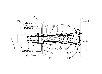
[0033] Figs.
3-3a show an embodiment wherein the system comprises a first injector 19
to inject feedstock 20 into the gas column and a second injector 21 for
injecting a liquid
22 into the gas column, with the second injector shown positioned downstream
and
adjacent to the first injector. For
this embodiment, the feedstock particle size
distribution is skewed, consisting only of particles in the optimal size range
and smaller.
Resultantly, the size of injector 19 and the speed of feedstock injection
produce the
penetration of the optimal feedstock particles 23 into region 15, while the
suboptimal
feedstock particles 25 are confined to the upper portion of region 16. The
optimal
feedstock particles 23 entrained in region 15 are transferred sufficient heat
and
momentum from the hot gas stream to impact substrate surface 6 and form an
optimal
quality coating 24, which is confined to the spot 17. The suboptimal feedstock
particles
25 entrained in the upper portion of region 16 are cooled by liquid 22, which
is primarily
entrained into the upper portion of region 16 by adjusting the size of
injector 21 and the
speed of liquid injection. As shown in Fig. 3, the cooling produced by liquid
22 can
reduce the degree of suboptimal feedstock particle melting to the point that
splat
formation is prevented, causing cooled suboptimal feedstock particles 27 to
hit surface 6
and bounce off without adhering and forming a coating. Thus, liquid 22 and
cooled
suboptimal feedstock particles 27 can impact surface 6 and act as abrasive
media,
removing the weakly-adhered feedstock and grit particles represented by
surface debris
26 ahead of the movement of spot 17 and the formation of coating 24.
Furthermore,
liquid 22 and cooled suboptimal feedstock particles 27 acting as abrasive
media on
surface 6 may dislodge embedded surface debris such as grit particles 28,
removing them
from the surface and preventing them from being entrapped in the coating.
Moreover, it
is possible that heating by the hot gas stream and cooling by the impinging
liquid may
cause the expansion and contraction of surface 6 and weakly-adhered/embedded
debris
particles 26 and 28, respectively, in a way that aids the removal of these
debris particles
from the surface. If an enhanced abrasive process is required, the liquid 22
may contain
a suspension of fine abrasive particulates, such as silicon or aluminum
oxides. The fine
particulates would be entrained in the upper portion of region 16 where they
would be
accelerated towards surface 6 without achieving the velocity or degree of
melting
necessary to adhere to surface 6 upon impact. These fine particulates would
therefore
enhance the removal of debris 26 and 28.
11
CA 02967578 2017-05-11
WO 2016/089452 PCT/US2015/040898
[0034] Figs. 4-4a depict an embodiment where the feedstock particle size
distribution is
Gaussian and contains particles below and above the optimal size range. In
this case,
larger than optimal particles 29 injected with the feedstock stream 20 would
penetrate
through region 15 and become entrained in the lower portion of region 16.
Because
these particles 29 do not receive sufficient heat and momentum in region 16,
they form a
suboptimal deposit, represented by surface debris 30, which trails the
movement of spot
17 and the formation of coating 24. As discussed here above with reference to
Fig. 3, the
smaller than optimal feedstock particulates 25 do not have enough momentum to
penetrate into region 15. As a result, suboptimal feedstock particles 25
entrain in region
16 where they do not receive enough heat and momentum to form optimal coating
24
upon impacting surface 6, so instead suboptimal feedstock particles 25 add to
surface
debris 26. The negative situations associated with surface debris 26 and 30
are resolved
by incorporating opposing liquid injectors 21 and 31, as shown in the
preferred
embodiment of Fig. 4. The size of injector 31 and the speed of injection are
adjusted so
that the entrainment of liquid 32 occurs substantially within the lower
portion of region
16. Some particles 29 are then cooled by liquid 32 to impact the substrate
with a degree
of melting that is insufficient to adhere to the substrate; these cooled
suboptimal
feedstock particles 33 hit surface 6 and bounce off without adhering and
forming a
coating. Thus, liquid 32 and suboptimal feedstock particles 33 can impact
surface 6 and
act as abrasive media, removing weakly-adhered surface debris 30 in the
portion of
region 18 trailing the motion of the spot 17 and the formation of coating 24.
This
cleaning mechanism may also remove from surface 6, embedded debris such as
grit
particle 34. Moreover, it is possible that heating by the hot gas stream and
cooling by
the impinging liquid may cause the expansion and contraction of surface 6 and
weakly-
adhered/embedded debris particles 30 and 34, respectively, in a way that aids
the
removal of these debris particles from the surface.
[0035] With regards to the upper portion of region 16, the mechanism of
action is the
same as described here above with reference to Fig. 3. The cooling of
suboptimal
feedstock particles 25 in region 16 by liquid 22 reduces adherence to surface
6 upon
impact. As shown in Fig. 4, some cooled suboptimal feedstock particles 27 hit
surface 6
and bounce off without adhering at all. Thus, liquid 22 and suboptimal
feedstock
particles 27 can impact surface 6 and act as abrasive media, removing the
weakly-
12
CA 02967578 2017-05-11
WO 2016/089452 PCT/US2015/040898
adhered feedstock and grit particles represented by surface debris 26 ahead of
the
movement of spot 17 and the formation of coating 24. Furthermore, liquid 22
and
suboptimal feedstock particles 27 acting as abrasive media on surface 6 may
dislodge
embedded surface debris, such as grit particle 28, removing them from the
surface and
preventing them from being entrapped into the coating. Moreover, it is
possible that
heating by the hot gas stream and cooling by the impinging liquid may cause
the
expansion and contraction of surface 6 and weakly-adhered/embedded debris
particles
26 and 28, respectively, in a way that aids the removal of these debris
particles from the
surface.
[0036] When increased output requires larger volumes of feedstock to be
injected,
multiple feedstock injectors can be distributed about axis 5 of the gas
stream. Fig. 5 of
the drawings presents another preferred embodiment of the system shown in Fig.
4 with
an additional feedstock injector 35 being located opposite to feedstock
injector 19. The
mechanism of injection and removal of suboptimal particulates and surface
debris is a
mirror of the mechanisms described for the embodiments shown in Fig. 3 and
Fig. 4.
[0037] In another embodiment of the present invention, Fig. 6 of the
drawings shows a
schematic front view of nozzle 3 with a plurality of feedstock injectors 19
and 35 and a
plurality of liquid injectors 21 and 31 arranged about axis 5.
[0038] Another preferred embodiment of the thermal spray system
incorporating the
invention is shown schematically in Fig. 7 of the drawings. The gas stream
column is
shown extending from nozzle 3 to substrate surface 6, the column having a
defined core
region 15 surrounding axis 5. Feedstock injector 19 is shown having flow
control valve 37.
Similarly, liquid injector 21 is shown having flow control valve 38. One of
each injector is
shown in Fig. 7; however, only one injector connected to both control valves
37 and 38
could be incorporated, or a plurality of injectors arranged about axis 5 may
be employed
as previously described with reference to Fig. 6. For the embodiment shown in
Fig. 7, in
a first step, the thermal spray system moves relative to surface 6 parallel to
arrow 8 to
deposit one or multiple layers of coating 11 or 24 in a manner described here
above with
reference to Fig. 1, 3, 4, or 5. In a second step, feedstock flow is stopped
with valve 37,
and the liquid velocity is adjusted with valve 38 so that the liquid is
entrained
substantially within region 15 of the gas stream. In a third step the thermal
spray system
moves relative to surface 6 in the direction(s) of arrow 8 and/or arrow 39 to
clean debris
13
CA 02967578 2017-05-11
WO 2016/089452 PCT/US2015/040898
particles 26 and 28 from surface 6 and coating 11 or 24 according to the
method
described here above with reference to Figs. 3, 4, or 5. In a fourth step,
control valve 37
is opened and the feedstock and liquid flows are adjusted to deposit one or
multiple
layers of coating 11 or 24 in a manner described here above with reference to
Figs. 1, 3,
4, or 5.
[0039] It is to be understood that variations and modifications can be made
on the
aforementioned structure without departing from the concepts of the present
invention,
and further it is to be understood that such concepts are intended to be
covered by the
following claims unless these claims by their language expressly state
otherwise.
14