Note: Descriptions are shown in the official language in which they were submitted.
CA 02967832 2017-05-12
WO 2016/081608 PCMJS2015/061356
PHOTON NEUTRALIZERS FOR NEUTRAL BEAM INJECTORS
FIELD
[0001] The subject matter described herein relates generally to neutral beam
injectors and, more
particularly, to a photon neutralizer for a neutral beam injector based on
negative ions.
BACKGROUND
[0002] A traditional approach to produce a neutral beam from a negative ion H-
, D- beam for
plasma heating or neutral beam assisted diagnostics, is to neutralize the
negative ion beam in a
gas or plasma target for detachment of the excess electrons. However, this
approach has a
significant limitation on efficiency. At present, for example, for designed
heating injectors with a
1 MeV beam [R.Hemsworth et al., 2009, Nucl. Fusion 49 045006], the
neutralization efficiency
in the gas and plasma targets will be about 60% and 85%, respectively [G. 1.
Dimov et al., 1975,
Nucl. Fusion 15, 551], which considerably affects the overall efficiency of
the injectors. In
addition, the application of such neutralizers is associated with
complications, including the
deterioration of vacuum conditions due to gas puffing and the appearance of
positive ions in the
atomic beam, which can be significant in some applications.
[0003] Photodetachment of an electron from high-energy negative ions is an
attractive method of
beam neutralization. Such method does not require a gas or plasma puffing into
the neutralizer
vessel, it does not produce positive ions, and it assists with beam cleaning
of fractions of
impurities due to negative ions. The photodetachment of an electron
corresponds to the following
process: H-+ hw = H +e. Similar to most negative ions, the H- ion has a single
stable state.
Nevertheless, photodetachment is possible from an excited state. The
photodetachment cross
section is well known [see, e.g., L.M.Branscomb et al., Phys. Rev. Lett. 98,
1028 (1955)]. The
photodetachment cross section is large enough in a broad photon energy range
which practically
overlaps all visible and near IR spectrums.
[0004] Such photons cannot knock out an electron from HO or all electrons from
H- and produce
positive ions. This approach was proposed in 1975 by J.H. Fink and A.M. Frank
[J.H. Fink et al.,
Photodetachment of electrons from negative ions in a 200 keV deuteriunz beam
source, Lawrence
Livermore Natl. Lab. (1975), UCRL-16844]. Since that time a number of projects
for photon
neutralizers have been proposed. As a rule, the photon neutralizer projects
have been based on an
84007678
optic resonator similar to Fabri-Perot cells. Such an optic resonator needs
mirrors with
very high reflectance and a powerful light source with a thin line, and all of
the optic
elements need to be tuned very precisely. For example, in a scheme considered
by Kovari
[M Kovari et al, Fusion Engineering and Design 85 (2010) 745-751], the
reflectance of
the mirrors is required to be not less than 99.96%, the total laser output
power is required
to be about 800 kW with output intensity of about 300W/cm2, and the laser
bandwidth is
required to be less than 100 Hz. It is unlikely that such parameters could be
realized
together.
[0005] Therefore, it is desirable to provide a non-resonance photo-
neutralizer.
SUMMARY OF INVENTION
[0006] Embodiments provided herein are directed to systems and methods for a
non-
resonance photo-neutralizer for negative ion-based neutral beam injectors. The
non-
resonance photo-neutralizer described herein is based on the principle of
nonresonant
photon accumulation, wherein the path of the photon becomes tangled and
trapped in a
certain space region, i.e., the photon trap. The trap is preferably formed as
two smooth
mirror surfaces facing each other with at least one surface being concave. In
the simplest
form, the trap is preferably elliptical in shape. A confinement region of the
trap is a region
near a family of normals that are common to both mirror surfaces of the trap.
The photons
with a sufficiently small angle of deviation from the nearest common normal
are confined.
Depending on specific conditions, the shape of the trap may be one of
spherical, elliptical,
cylindrical, toroidal, or a combination thereof.
[0007] In operation, photon beams with a given angular spread along and across
the trap
are injected through one or more small holes in one or more of the mirrors.
The photon
beams can be from standard industrial power fiber lasers. The photo
neutralizer does not
require high quality laser radiation sources pumping a photon target, nor does
it require
very high precision adjustment and alignment of the optic elements.
[0007a] According to some embodiments disclosed herein, there is provided a
non-
resonance photo-neutralizer for neutral beam injectors comprising first and
second mirrors
having opposing mirror surfaces, the first and second mirrors being positioned
in spaced
relation and extending longitudinally in a first direction, the first mirror
having a central
portion and opposing first and second ends spaced apart from the central
portion in the
first direction, the first mirror extending in the first direction from the
first end along the
2
Date Recue/Date Received 2022-03-15
84007678
central portion to the second end and bending along the first direction toward
the second
mirror with the first and second ends of the first minor being positioned
closer to the
second minor than the central portion of the first minor, wherein the minor
surface of the
first mirror is concave in a second direction transverse to the first
direction.
[0007b] According to some embodiments disclosed herein, there is provided a
negative ion
based neutral beam injector comprising a negative ion source, and a non-
resonance photo-
neutralizer co-axially positioned with the negative ion source, wherein the
photo-
neutralizer including first and second mirrors having opposing minor surfaces,
the first
and second minors being positioned in spaced relation and extending
longitudinally in a
first direction, the first minor having a central portion and opposing first
and second ends
spaced apart from the central portion in the first direction, the first mirror
extending in the
first direction from the first end along the central portion to the second end
and bending
along the first direction toward the second mirror with the first and second
ends of the first
mirror being positioned closer to the second mirror than the central portion
of the first
mirror, wherein the minor surface of the first mirror is concave in a second
direction
transverse to the first direction.
[0008] Other systems, methods, features and advantages of the example
embodiments will
be or will become apparent to one with skill in the art upon examination of
the following
figures and detailed description.
2a
Date Recue/Date Received 2022-03-15
CA 02967832 2017-05-12
WO 2016/081608 PCT/US2015/061356
BRIEF DESCRIPTION OF FIGURES
[0009] The details of the example embodiments, including structure and
operation, may be
gleaned in part by study of the accompanying figures, in which like reference
numerals refer to
like parts. The components in the figures are not necessarily to scale,
emphasis instead being
placed upon illustrating the principles of the invention. Moreover, all
illustrations are intended
to convey concepts, where relative sizes, shapes and other detailed attributes
may be illustrated
schematically rather than literally or precisely.
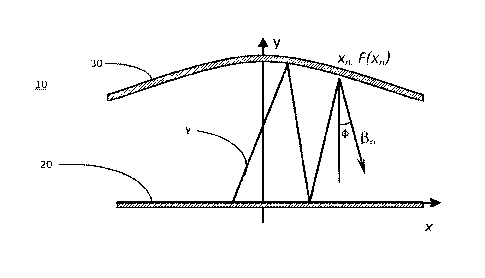
[0010] FIGURE 1 is a schematic of a non-resonance photon trap.
[0011] FIGURE 2 is a schematic of a quasiplanar adiabatic optical trap.
[0012] FIGURE 3 is a perspective view schematic of the quasiplanar adiabatic
optical trap
shown in Figure 2.
[0013] FIGURE 4 is a trace of a single ray in the photon trap with a random
angle from -3 to
in the XY plane, and -5 to 5 along the trap, the number of reflections is
4000. The cone
angle of end mirrors is about 30
.
[0014] FIGURE 5 illustrates an example of the surface intensity distribution
and its cross profile
in the middle of the trap.
[0015] FIGURE 6 is a chart showing the degree of neutralization (dotted line)
and overall
neutralizer efficiency (continuous curve) vs laser injection power.
[0016] FIGURE 7 is a plan view of a negative ion-based neutral beam injector
layout.
[0017] FIGURE 8 is a sectional isometric view of the negative ion-based
neutral beam injector
shown in Figure 7.
[0018] It should be noted that elements of similar structures or functions are
generally
represented by like reference numerals for illustrative purpose throughout the
figures. It should
also be noted that the figures are only intended to facilitate the description
of the preferred
embodiments.
DETAILED DESCRIPTION
[0019] Each of the additional features and teachings disclosed below can be
utilized separately
or in conjunction with other features and teachings to provide a non-resonance
photo-neutralizer
for negative ion-based neutral beam injectors. Representative examples of the
embodiments
described herein, which examples utilize many of these additional features and
teachings both
3
84007678
separately and in combination, will now be described in further detail with
reference to the
attached drawings. This detailed description is merely intended to teach a
person of skill in the
art further details for practicing preferred aspects of the present teachings
and is not intended to
limit the scope of the invention. Therefore, combinations of features and
steps disclosed in the
following detail description may not be necessary to practice the invention in
the broadest sense,
and arc instead taught merely to particularly describe representative examples
of the present
teachings.
[00201 Moreover, the various features of the representative examples and the
dependent claims
may be combined in ways that are not specifically and explicitly enumerated in
order to provide
additional useful embodiments of the present teachings. In addition, it is
expressly noted that all
features disclosed in the description and/or the claims are intended to be
disclosed separately and
independently from each other for the purpose of original disclosure, as well
as for the purpose
of restricting the claimed subject matter independent of the compositions of
the features in the
embodiments and/or the claims. It is also expressly noted that all value
ranges or indications of
groups of entities disclose every possible intermediate value or intermediate
entity for the
purpose of original disclosure, as well as for the purpose of restricting the
claimed subject
matter.
[0021] Embodiments provided herein are directed to a new non-resonance photo-
neutralizer for
negative ion-based neutral beam injectors. A detailed discussion of a negative
ion-based neutral
beam injector is provided in Russian Patent Application No. 2012137795 and PCT
application
No. PCT/1JS2013/058093.
[0022] The non-resonance photo-neutralizer described herein is based on the
principle of
nonresonant photon accumulation, wherein the path of the photon becomes
tangled and trapped
in a certain space region, i.e., the photon trap. The trap is preferably
formed as two smooth
minor surfaces facing each other with at least one surface being concave. In
the simplest form,
the trap is preferably elliptical in shape. A confinement region of the trap
is a region near a
family of normals that are common to both mirror surfaces of the trap. The
photons with a
sufficiently small angle of deviation from the nearest common normal are
confined. Depending
on specific conditions, the shape of the trap may be one of spherical,
elliptical, cylindrical,
toroidal, or a combination thereof.
4
Date Recue/Date Received 2022-03-15
CA 02967832 2017-05-12
WO 2016/081608 PCT/US2015/061356
[0023] In operation, photon beams with a given angular spread along and across
the trap are
injected through one or more small holes in one or more of the mirrors. The
photon beams can
be from standard industrial power fiber lasers. The photo neutralizer does not
require high
quality laser radiation sources pumping a photon target, nor does it require
very high precision
adjustment and alignment of the optic elements.
[0024] Turning to the figures, an embodiment of a non-resonance photon trap 10
is shown in
Figure 1. As depicted in a two-dimensional case, the trap 10 comprises a
bottom flat mirror 20
and a top concave mirror 30. A photon y with a small angle to vertical axes
within the trap 10,
will develop with each reflection from the upper mirror 30 some horizontal
momentum
difference to central axes of trap 10. The position of the photon y after an n-
th reflection is
defined by the abscissa of a reflection point, x,,, with a height, F(xõ), an
angle cp from a vertical
and a photon speed, fir. The horizontal motion is described by the following
system of
equations:
x,1 ¨x,, = (F (xõ, )+F ( xõ ))t,g13õ (1)
dF (xõH,)
Ail fin 2 _____________________________________________________________ (2)
dx
[0025] For stability investigation, linearize versions of equations (1)and (2)
are combined and
the following equations are obtained:
, ¨ xõ = 2F (0)13õ (3)
d2F (0)
13,1 13õ 2 ______________________ xõ,
eL,2 (4)
[0026] By combining equations (3) and (4), the following linear recurrence
relation is obtained:
= 4F (0)d 2 F (0) 2 _____________________ x_1õ
dx
(5)
¨(u)¨
R
where R is the curvature radius of top mirror 30. Equation (5) is a type of
finite-difference
Ischeme for an oscillation system with unit time step and with Eigen frequency
co, ¨ 2 F(0). The
R
solution is representable in the form xõ = A = qn , where q is a complex
number. Then for q
CA 02967832 2017-05-12
WO 2016/081608
PCT/1JS2015/061356
defined as:
2F (0) I2F (0)\ 2
q 1 ,2 1 ___ I 1 ___ 1 (6)
The stability condition is q , from
which photons confinement in a geometric optic, when
taking into account non-negativity of value R , is determined as
F (0) < R, wo2 < 4 (7)
The curvature radius of the upper mirror 30 impacts photon confinement.
Recurrent systems (1)
and (2) allow the production of the integral of motion:
tgia. (fl. 1- Ja.) =
v 2 (x,, ¨ x,,) dF (xõõ) (8)
F(x.õ)+F(xõ) dx
In the case of a sufficiently small curvature of the upper mirror 30 and small
steps, such as
AF F, ¨dF 1, Afi 1, (9)
dx
the integral sums (8) is approximately transformed into
ln cos /30 = in F(x)
cosfl F(x0)
or into standard adiabatic invariant
F (x) cos(fl)=const (10)
Relation (10) determines the region filled by photons.
[0027] These estimations enable the design of an effective photon neutralizer
for negative ion
beams. Turning to Figures 2 and 3, a reasonable three-dimensional geometry of
the trap 10 is a
long arch assembly of four components. As depicted in Figure 2, the trap 10
preferably
comprises a bottom or lower mirror 20 at the bottom of the trap 10 that is
planar or flat in shape,
and an upper mirror assembly 30 comprising a central mirror 32 that is
cylindrical in shape, and
6
CA 02967832 2017-05-12
WO 2016/081608 PCT/US2015/061356
a pair of outer mirrors 34 that are conical in shape and coupled to the ends
of the central mirror
32. As shown, an ion beam 1-1- is passed along the photon trap. The sizes are
taken from the
characteristic scales of a single neutralizer channel of a beam injector for
the International
Thermonuclear Experimental Reactor (ITER).
[0028] The following provides results of a numerical simulation of a photon
neutralizer for ITER
NBI. This simulation has been carried out by using ZEMAX code. Figure 4 shows
a one ray
trace in the trap system 10 given in Figure 2 with a random angle from -3 to
30 in the XY plane,
and -5 to 50 along the trap 10.
[0029] The trajectory presented in Figure 4 contains 4000 reflections, after
which the ray
remained in the trap system. In a resonance device [M. Kovari, B. Crowley.
Fusion Eng. Des.
2010, v.85 p. 745-751], the storage efficiency under a mirror reflectance
1,2=0.9996 is about
500. In the case noted herein, with a lower mirror reflectance of r2=0.999,
the determined
Ph,
storage efficiency is
___________________________ -1000 (11)
[0030] Losses will tend to be associated chiefly with a large number of
surfaces inside the cavity
and diffraction. V.H. Fink, Production and Neutralization of Negative Ions and
Beams: 3rd Int.
Symposium, Brookhaven 1983, AIP, New York, 1984, pp. 547-560]
[0031] The distribution of the radiant energy flux through a horizontal plane
inside the trap 10 is
shown in Figure 5, where the reflection coefficient of all surfaces is equal
to 0.999 and the input
radiant power is equal to 1 W. The calculated accumulated power in the cavity
of the trap 10 is
equal to 722 watts. Taking into account calculation losses (Zemax code
monitors and evaluates
such losses) the accumulated power value should be increased by 248 watts.
Therefore the
storing efficiency reaches almost a maximum possible value (11). Thus, quasi-
planar systems
allow within the geometrical optics the creation of a confinement region with
a given size.
[0032] Note, that the end cone mirrors 34 and main cylindrical mirrors 32 and
20 form broken
surface as shown in Figures 2 and 3. The broken surfaces tend to have a
negative effect on the
longitudinal confinement of photons because this forms an instability region
(see (7)). However,
the number of crossings of these borders by a ray during the photon lifetime
is not large in
comparison with the total number of reflections, and, thus, the photon does
not have time to
significantly increase longitudinal angle and leave the trap through the ends
of the trap 10.
7
84007678
Radiation injection into trap and sources
[0033] To pump the optic cell, photons beams with a given angular spread along
and across the
trap 10 can be injected through one or more small holes in one or more
mirrors. For example, it
is possible by using a ytterbium fiber laser (X=1070nm, total power above 50
kW)
[See for example lasers manufactured by IPG Photonics Corporation]. These
serial lasers have
sufficient power and their emission line is near optimal.
[0034] The radiation beam with necessary angular spread can be prepared from
fiber laser
radiation by special adiabatic conical or parabolic shapers. For example,
radiation with a spread
of 15 from fiber and 03014t may be transformed to 5 and 01 mm, which is
sufficient for the
neutralizer trap 10 described herein.
Efficiency of photon neutralization
[0035] The degree of neutralization is representable as
P
K (P) ¨1¨ exp V (12)
od
where d is the width of the neutralization region, Eo is the photon energy, V
is the velocity of the
ions. P is the total accumulated power defined as P = , where
Po is the optic pumping power.
The neutralization efficiency of D- flux by the laser with overall efficiency
171 may be determined
as
K(P)P
17(150)¨
P +PI(13)
77/
where P is the negative ion beam power. The efficiency increases with growth
of D- beam
power. The efficiency (13) and degree of neutralization (12) are shown in
Figure 6. This curve
has been calculated for a single channel gas neutralizer in ITER injectors, in
which 10 MW part
is passed. Thus, in such an approach nearly 100% neutralization can be
achieved with very high
energetic efficiency of about 90%. For comparison, ITER neutral beam injector
has a 58%
neutralization [R. Hemsworth et al.// Nucl. Fusion. 2009, v.49, 045006] and
correspondently the
same efficiency. The overall injector efficiency while taking into account
accelerator supply and
transport losses has been estimated by Krylov [A. Krylov, R.S. Hemsworth.
Fusion Eng. Des.
2006, v.81, p. 2239-2248].
8
Date Recue/Date Received 2022-03-15
84007678
[0036] A preferred arrangement of an example embodiment of a negative ion-
based neutral
beam injector 100 is illustrated in Figures 7 and 8. As depicted, the injector
100 includes an ion
source 110, a gate valve 120, deflecting magnets 130 for deflecting a low
energy beam line, an
insulator¨support 140, a high energy accelerator 150, a gate valve 160, a
neutralizer tube (shown
schematically) 170, a separating magnet (shown schematically) 180, a gate
valve 190, pumping
panels 200 and 202, a vacuum tank 210 (which is part of a vacuum vessel 250
discussed below),
cryosorption pumps 220, and a triplet of quadrupole lenses 230. The injector
100, as noted,
comprises an ion source 110, an accelerator 150 and a neutralizer 170 to
produce about a 5 MW
neutral beam with energy of about 0.50 to 1.0 MeV. The ion source 110 is
located inside the
vacuum tank 210 and produces a 9 A negative ion beam. The vacuum tank 210 is
biased to -880
kV which is relative to ground and installed on insulating supports 140 inside
a larger diameter
tank 240 filled with SF6 gas. The ions produced by the ion source are pre-
accelerated to 120 keV
before injection into the high-energy accelerator 150 by an electrostatic
multi aperture grid pre-
accelerator 111 in the ion source 110, which is used to extract ion beams from
the plasma and
accelerate to some fraction of the required beam energy. The 120 keV beam from
the ion source
110 passes through a pair of deflecting magnets 130, which enable the beam to
shift off axis
before entering the high energy accelerator 150. The pumping panels 202 shown
between the
deflecting magnets 130 include a partition and cesium trap.
[0037] A more detailed discussion of the negative ion-based neutral beam
injector is provided in
Russian Patent Application No. 2012137795 and PCT application No.
PCT/US2013/058093.
[0038] The example embodiments provided herein, however, are merely intended
as illustrative
examples and not to be limiting in any way.
[0039] In the foregoing specification, the invention has been described with
reference to specific
embodiments thereof. It will, however, be evident that various modifications
and changes may
be made thereto without departing from the broader spirit and scope of the
invention. For
example, the reader is to understand that the specific ordering and
combination of process
actions shown in the process flow diagrams described herein is merely
illustrative, unless
otherwise stated, and the invention can be performed using different or
additional process
actions, or a different combination or ordering of process actions. As another
example, each
feature of one embodiment can be mixed and matched with other features shown
in other
9
Date Recue/Date Received 2022-03-15
CA 02967832 2017-05-12
WO 2016/081608 PCT/US2015/061356
embodiments. Features and processes known to those of ordinary skill may
similarly be
incorporated as desired. Additionally and obviously, features may be added or
subtracted as
desired. Accordingly, the invention is not to be restricted except in light of
the attached claims
and their equivalents.