Note: Descriptions are shown in the official language in which they were submitted.
CA 2967891 2017-05-19
CONSTRUCTION TOY WITH INTERLOCKING ELEMENTS
[1] The present invention relates to a construction toy apparatus that
permits a child to
build a wide variety for building structures. The toy permits easy,
affirmative joining of
construction pieces to build a wide variety of structures to stimulate a young
child's imagination.
[2] Frequently, tile-based construction toys are limited by the fact that
one side is always
male and the other is always female. It is the object of the present invention
to offer
hermaphroditic tiles that can be joined no matter the orientation of the tile.
BACKGROUND
[3] It is generally accepted knowledge that the earlier neural pathways are
formed, the
quicker a person can learn more sophisticated skills relating to those
pathways. For example, the
difference between starting to practice the violin at the age of 4 rather than
8 is more remarkable
than the difference between the age of 8 and 12.
[4] The present invention allows curious young minds to expand their
imagination. The
construction tiles of the present invention can be used to build two-
dimensional and three-
dimensional structures due to the fact that each tile has interlocking
elements around its
periphery. The unique joining means between tiles of the present invention
results in creations
that can comprise an even or odd number of tiles. The tiles will lock together
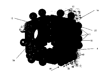
notwithstanding
CA 2967891 2017-05-19
2
their shapes. For example, a pentagon tile can be joined to five triangle
tiles, that will all join
together to form a five-sided pyramid. This is due to the fact that the
present invention's
interlocking elements are hermaphroditic on each side.
[5] There is known US8187050 for "Toy-Building Elements Having Sidewall
Grooves
Formed Between Outwardly Extending Flexible Ridges" relating to construction
elements that
can interact with any other elements regardless of their gender. However,
there is no hinge-type
or axial locking feature, and once locked the elements cannot pivot to suit a
child's construction
objective.
[6] There is known US6301747 for "Resilient Hinge Connection and CD Holder
Box or
Photograph Frame Utilizing the Same", which is sold as a toy for children
called "Clics". The
square tiles of this invention have alternating male and female connectors
around the periphery
that snap together to form two and three-dimensional structures. However, this
patent is inferior
to the present invention due to the fact that resulting structures can have
only an even number of
tiles, since a male side will not mate with a male side. The child has to keep
track of how
adjacent tiles are related in order to build a successful structure. The
present invention has both a
male and female connector on each side, making the orientation relationship
between adjacent
tiles irrelevant.
[7] There is known US3597874 for "Releasably Interlocking Units Having a
Snap
Connection" that describes a toy construction set with connectable members. In
the embodiment
described on Figure 4 of this patent, the interlocking members have opposed
concave recesses
permitting the end portion of one unit to snap between a pair of end portions
on another unit. The
only similarity between the present invention and cited patent resides in the
fact that there is a
mating between a concave and convex surface. However, the cited patent has two
elements
sandwiching one opposing element, thus requiring a minimum of three elements,
whereas the
locking feature of the present invention necessitates a minimum of four
elements, two on each
side. In addition, as described on Figure 4 of the cited patent, the units
cannot be locked together
in the same plane as tiles of the present invention, and require a turn of 90
between each unit.
[8] There is also known US6109997 for "Toy Building Set Comprising a Number
of
Transmission Elements" describing toothed wheels with four spokes that can
intercooperate with
spokes of other toothed wheels due to the fact that the convex abutment
surfaces are the same as
the concave abutment surfaces of the neighboring wheels. However, this
invention is for building
CA 2967891 2017-05-19
3
more sophisticated constructions such as cars, cranes and machines that
require a variety of gear
functions. Said wheels are not tiles for building 2D and 3D structures, and
are not safe for
children under the age of 4.
[9] Finally, there is known US6925770 for "Interlockable Element for
Structure Assembly
Set" comprising a tile with interlocking elements around its periphery. Each
element comprises a
plurality of prongs that cooperate with prongs on neighboring tiles to lock
said tiles together in
various angles. Each tile of cited patent has 24 prongs that cooperate with
adjacent prongs by
bending slightly out of position and snapping back. This patent is more
complicated than the
present invention, and a tile of cited patent will be useless if one of the 24
flimsy prongs should
break.
[1o] The advantages of this invention over all prior art is that it
offers both axial rotatability
of the formed joint like a hinge, and the ability to join any side to any
other side notwithstanding
the side's gender. This means that a child can make structures with odd or
even number of tiles,
without boundaries set by gender-specific joining systems.
OBJECT OF THE PRESENT INVENTION
[11] The present invention is designed to safely stimulate the imagination
of a child and
offer a great flexibility of potential creations without inherent limitations.
Tiles will always
cooperate with each other, notwithstanding their geometry and connection
gender. The child will
be able to build structures in two and three dimensions, and the parent will
be able to start
stimulation of the child's cognitive and spatial relativity skill sets at an
early age.
[12] This invention's blocks or tiles with interconnecting elements on each
periphery
securely lock said tiles together, permitting a child to build structures.
Said tiles also have
receiving cavities in their centers for being joined together using elongated
connectors, adding a
dimension of connectability to the invention's experience. These elongated
connectors allow the
tiles to rotate around the axis so that if the child builds a model of an
animal, this rotation
simulates how a head turns on a body.
BRIEF DESCRIPTION OF THE DRAWINGS
[13] Figure 1 shows the preferred embodiment of the present invention.
[14] Figure 2 shows another embodiment of the present invention.
CA 2967891 2017-05-19
4
[15] Figure 3 shows other embodiments of the present invention.
[16] Figure 4 shows elongated connectors for expanding structures.
[17] Figure 5 shows a three-dimensional structure made with the present
invention.
[18] Figure 6 demonstrates attachment of an elongated connector.
[19] Figure 7 shows a two-dimensional structure made with the present
invention.
[20] Figure 8 shows a variant on location of connecting means.
[21] Figure 9 shows another embodiment of the present invention.
[22] Figure 10 shows interlocking means of the embodiment of Figure 9.
[23] Figure 11 shows another interlocking means of the embodiment of Figure
9.
[24] Figure 12 shows yet another interlocking means of the embodiment of
Figure 9.
[25] Figure 13 shows still another interlocking means of the embodiment of
Figure 9.
[26] Figure 14 shows an expanding means to customize elongated connectors
of Figure 4.
[27] Figure 15 shows a construction of a bird made with the present
invention.
[28] Figure 16 shows an expanded view of Figure 15.
DETAILED DESCRIPTION OF THE PREFERRED EMBODIMENT
[29] The present invention refers to a child-friendly safe interlocking
building block or tile
system for constructing two- and three-dimensional structures. The
interlocking feature of the
present invention comprises cooperation between a novel interlocking element
system, wherein
male and female portions lock together in a lattice format.
[30] Due to the fact that each side's interlocking means are
hermaphroditic, the possibilities
of intercooperation between tiles are more numerous than if a tile's side were
only male or only
female. Notwithstanding the geometric shape of adjacent tiles, their sides
will click or join
together. The added feature of the interlocking means being similar to hinge
knuckles allow
rotation of one tile with relation to another, permitting a wide range of
structures only limited by
the imagination.
[31] Referring now to drawings, Figure 1 shows the preferred embodiment of
the present
invention, namely construction tile 2. Tile 2 is substantially square and
flat. Tile 2 comprises
square body 4 with a top portion 6, bottom portion 8, and tile periphery 10.
Interlocking elements
12 protrude from periphery 10, and each element 12 comprises cylindrical stem
14 that connects
CA 2967891 2017-05-19
periphery 10 to interlocking means 15. Stem 14 is adapted to flex during
locking and unlocking
of said interlocking elements 12.
[32] Interlocking means 15 comprise either an interlocking means with a
male mating
portion 16 or a female mating portion 17. Said male interlocking means 16
comprises a sphere
incorporating male mating portion 20, and said female interlocking means 17
comprises a
sphere, on one side with a concavity or female locking portion 18, and on the
other side a neutral
mating portion 22, being substantially flat. It must be emphasized that
neutral mating portion 22
is not essential to the functionality of the present invention. If there were
no neutral mating
portion 22, the invention would still work as designed, but it would be
aesthetically less pleasing
since there would be two interlocking means 15 on one side and two
interlocking means 15 on
the other side. With neutral mating portion 22, the four interlocking means 15
are aligned
straight and evenly.
[33] Tile body 4 also has a receiving cavity 28 substantially in its
center, comprising a round
hole adapted to receive and lock elongated connector 26 or short connector 30,
as seen on Figure
4. Said locking of elongated connector 26 or short connector 30 is
accomplished by receiving
cavity 28's female mating portion 29, adapted to receive a male mating portion
27 of elongated
connector 26 or short connector 30, seen on Figure 4.
[34] Figure 2 shows another embodiment of the present invention, wherein
interlocking
means 15 are not spherical but flattened, resembling clothing buttons.
Interlocking portions 16
and 17 are configured identical to the embodiment in Figure 1, with female
mating portions 18
and male mating portions 20 intercooperating as described in Figure 1.
[35] Figure 3 demonstrates various embodiments of body 4 shapes that can be
operably used
for the present invention. Due to the fact that each side's interlocking means
15 is
hermaphroditic, any shape can be joined to any other shape.
[36] Figure 4 shows elongated connectors 26 of various lengths, and short
connector 30.
Elongated connectors 26 and short connector 30 comprise a cylindrical body
with male mating
portions 27 on the ends. Short connector 30 is used to affix two tiles 2 in
close proximity so that
the two tiles 2 are stacked, to simulate a neck between a body and a head (as
seen on Figures 15
and 16). The head will be able to rotate about the body. Short connector 30
can also serve as a
cosmetic feature such as an eye of an animal, as seen on Figures 15 and 16.
CA 2967891 2017-05-19
6
[37] Short connector 30 is also necessary if one tile 2 has all
interlocking means 15
populated by other tiles 2, and the user needs a fresh tile 2 with all
interlocking means 15
available for additional tiles 2. For example, if the user is making a model
of a bird (see Figures
15 and 16), short connector 30 would connect the tile 2 that makes part of the
bird's body to the
tile 2 that makes part of the bird's head. This short connector 30 would allow
the bird's head to
rotate, similar to a real bird's range of motion.
[38] Figure 5 shows a sample three-dimensional structure 34 comprising four
tiles 2,
wherein interlocking elements 12 around tile periphery 10 are interlocked with
adjacent
interlocking elements 12 between tiles 2. Male mating portions 20 cooperate
with female mating
portions 18 to provide a secure lock. Force vectors 40 retain interlocking
elements 12 together.
In the preferred embodiment, there are a minimum of two interlocking elements
12 on each tile
periphery 10, said elements 12 are spaced so that there is a gap between them
wide enough to
accept an interlocking element 12 from another tile 2. In the resulting joint
shown on Figure 5,
there are four elements 12, two being on the inside and two being on the
outside of said joint.
There are three points of contact 13 between the four elements 12. For the
invention to function
properly, there must be no gap or space between the middle point of contact
13, between the two
inside elements 12. If there is any gap or space between points of contact 13,
the invention will
not work. This is particularly true if there is a gap between point of contact
13 between the two
inside elements 12.
[39] Figure 6 shows elongated connector 26 inserted into elongated
connector receiving
cavity 28 in tile body's 4. It should be pointed out that cavity 28 can
simultaneously
accommodate two connectors 26, one connector 26 on top 6 and one connector 26
on the bottom
8 of tile body 4.
[40] Figure 7 shows a sample two-dimensional structure 32, with force
vectors 40 exerting
force on interlocking means 12, holding tiles 2 together.
[41] Figure 8 shows a second variant of the preferred embodiment, wherein
male and female
interlocking means 16 and 17 are swapped places. It should be noted that this
second variant will
work as well as the first variant.
[42] Figure 9 shows another embodiment of the present invention, being a
hinge-type tile
36. Tile 36 comprises interlocking elements 12 without stems 14, resembling
hinge knuckles. As
seen on Figure 10, tile 36 also has female and male mating portions 18 and 20
on interlocking
CA 2967891 2017-05-19
7
means with male mating portions 16 and female mating portions 17. As in the
first embodiment,
interlocking element with male mating portion 16 has a neutral mating portion
22. Cavity 28
receives elongated connector 26 or short connector 30 by means of female
mating means 29
comprising protruding half-spheres inside cavity 28's circumference that lock
elongated
connector 26's or short connector 30's male mating means 27.
[43] Figure 11 demonstrates a variant in female and male mating portions 18
and 20, being
of a square-walled configuration. This configuration allows the tiles to be
positively locked at
90 and 1800 rather than a fluid, axial connection 24 as seen on Figure 9.
Figure 12 shows
another variant of female and male mating portions 18 and 20 with octagonal
walls, and Figure
13 shows polygonal walls. It should be noted that the present embodiment of
the positive locking
variant is not restricted to the demonstrated variants, and is functional with
any number of walls
of the female and male mating portions 18 and 20 for a positive-locking
intercooperation. It is
also important to note that said positive locking variant can be incorporated
on the first
embodiment that is shown on Figures 1- 8.
[44] Figure 14 shows an elongated connector expander 38 for customizing the
length of
elongated connectors 26 or short connectors 30, comprising a ring with a
female connector 29 on
each side for joining two elongated connectors 26 or short connectors 30 end
to end. For
example, if a user needs to create an elongated connector 26 of a specific
length that is not
provided, she can use expanders 38 and a plurality of elongated connectors 26
to create the
desired length.
[45] Figures 15 and 16 demonstrate a construction 42 of a bird out of tiles
2, elongated
connectors 26 and short connectors 30. There are approximately sixty pieces in
construction 42.
Elongated connector 30 serves as both a neck connecting construction 42's head
to body, as well
as the eyes. Construction 42 can be animated to an identical degree as a real
bird: the wings can
pivot and be modeled as the child sees fit, the head can turn, the beak can
open and close, and the
legs can rotate.
[46] As seen on Figure 16, short connectors 30 permit adjacent placement of
tiles 2 to
expand a construction indefinitely. The body is connected to a neck, which is
connected to a
head. Said neck comprises one square tile 2 and four triangular tiles 2. All
interlocking elements
12 cooperate to join together due to the hermaphroditic nature of the
interlocking means 15.
CA 2967891 2017-05-19
8
[47] It should be noted that in the present embodiments, the invention is
inoperable unless
there are a minimum of two interlocking elements 12 on each periphery 10 of
tile 2, and tiles 2
will only interlock as long as tops 6 of each tile are oriented in the same
plane. In the preferred
embodiment, tiles 2 will not interlock if top 6 and bottom 8 are oriented in
the same plane. In any
resulting joint of four interlocking elements 12, there will always be two
outside and two inside
interlocking elements 12.
[48] Regarding tile 36 of Fig. 10, since there is no stem 14 to flex during
connection, it
should be noted that the size of the male mating portion 20 is directly
proportional to the
flexibility of the material of manufacture for tile 36. For example, if tile
36 is made of a very stiff
plastic, male mating portion 20 is relatively small to permit interlocking
elements 12 to lock.
However, if tile 36 is made of very flexible foam, male mating portion 20
should be substantially
larger so as not to slip out after mating with female mating portion 20 due to
the material's pliant
nature. The same principle applies to the embodiment shown on Figures 1 ¨ 8.
[49] In operation, referring to Figures 1 ¨ 8, user positions tiles 2 so
that tops 6 are both in
the same plane, and moves interlocking elements 12 towards each other so that
female
interlocking elements 17 are between male interlocking elements 16. Once
interlocking means
15 from two adjoining tiles 2 abut each other, user pushes tiles 2 together so
that convex male
mating portions 20 on interlocking means 16 slip into concave female mating
portions 18 on
interlocking means 17. Interlocking elements 12 will flex slightly on stems 14
to permit
interlocking means 16 to overcome resilient resistance of interlocking means
17, and seat male
mating portion 20 securely into female mating portion 18.
[50] The resulting lock permits one tile 2 to rotate about an axis 24 with
said second tile 2,
thus allowing building of two- or three-dimensional structures. User can
insert elongated
connectors 26 or short connectors 30 into receiving cavities 28 on either the
top 6, bottom 8, or
both top and bottom 6 and 8 to expand the 2D or 3D construction 32 or 34.
[51] Referring to Figures 9 ¨ 13, user aligns tiles 36 so that tops 6 are
in the same plane, and
pushes tiles 36 together so that interlocking elements 12 interconnect, the
interlocking means
with male mating portion 16 is directly adjacent to the interlocking means
with female mating
portion 17. User pushes tiles 36 together until male mating portion 20 locks
within female
mating portion 18. Depending on the variant, the resulting joint will be axial
24 (see Figure 9) or
a positive lock without any rotation about the joint's axis.
CA 2967891 2017-05-19
9
[52]
Force vectors 40 keep the resulting joint from loosening due to the fact
that one vector
40 is applied inwardly on the joint by one tile 2's outside interlocking
element 12, and another
vector 40 is being applied in the opposite direction on the joint by the other
tile 2's outside
interlocking element 12.