Note: Descriptions are shown in the official language in which they were submitted.
CA 02968492 2017-05-19
WO 2016/079574 PCT/IB2014/066309
1
AGITATOR MEANS FOR VERTICAL GRINDING MILLS
FIELD OF THE INVENTION
The present invention relates to an agitator means for a vertical
grinding mill comprising a screw flight system having a shaft and at least one
screw flight. The present invention further relates to a vertical grinding
mill
comprising above agitation means, and a construction assembly for said
agitation means.
BACKGROUND
Vertical grinding mills are known, e.g., from US 4,660,776 and from the
brochure "VERTIM ILL TM- Fine and ultrafine wet grinding". A vertical grinding
mill has a chamber in which an agitator is arranged. Grinding media, which
may be made out of e.g. steel or ceramics and which may have different
shapes, such as balls or natural pebbles, is provided in the chamber. Water,
the material to be ground, and optionally additives are fed into the chamber.
By rotating the agitator, the charge is agitated, such that the grinding media
grinds the material to be ground by abrasion and attrition. The two references
mentioned above disclose vertically arranged stirred mills. However, the
same general principle is used in stirred mills with e.g. tilted arrangement.
The chamber retains the grinding media and, in case of a vertically
arranged mill, the chamber also supports the drive components including the
agitator.
The agitator which rotates and imparts motion to the grinding media
consists, in the VERTIMILLTm, of an inner welded screw flight system that
supports a number of outer wear liners, which are bolted onto the welded
screw flight system. The welded screw flight system according to this prior
art
is composed of a shaft, and a number of screw flights, which are welded onto
the shaft to form a continuous helical blade longitudinal of the shaft.
In US 4,242,002 another agitator means has been disclosed for a
vertical grinding mill. This agitator means also has an inner welded blade
along a centre shaft in form of a screw. Said inner welded blade is disclosed
to have a relative small diameter, measured from the centre of the shaft,
while
CA 02968492 2017-05-19
WO 2016/079574
PCT/IB2014/066309
2
a number of outer blade units having relative large diameter, measured from
the centre of the shaft, and a screw pitch equal to the same of the inner
blade
are positioned side by side along the periphery of the inner blade and are
fixed to the inner blade by means of bolts and nuts so that a continuous screw
blade assembly is formed by the inner blade and a number of outer blade
units.
While these known vertical grinding mills perform satisfactory, mining
operations are more and more located in remote locations with limited access
and restricted shipping possibilities. Some sites are not even accessible by
road but only by rail and this further limits the size of the shipping
components
to specific dimensions to fit through train tunnels. At the same time, the
mining operations call for larger vertical grinding mills to process larger
tonnages for low grade ore bodies with finely disseminated valuable minerals
to be recovered more economically. Further, from a manufacturing point of
view, the larger the mills and the components become, the possible sites
where the components may be manufactured decreases, which further
increase the shipping costs and lead times. Further, the larger the stirred
mill,
the greater the costs are to meet various shipping restrictions for the
components.
SUMMARY
An object of the invention is to provide agitator means, which requires
less transportation space.
Another object of the invention is to provide agitator means, which is
easier to manufacture.
According to a first aspect of the invention, these and other objects are
achieved, in full or at least in part, by agitator means for a vertical
grinding
mill, which agitator means comprises a screw flight system having a shaft and
at least one screw flight, wherein said screw flight system is provided in at
least two segments, wherein each segment comprises at least one screw
flight section integral to a shaft section, and wherein said at least two
segments are arranged for assembling to one another to form said screw
flight system.
CA 02968492 2017-05-19
WO 2016/079574 PCT/IB2014/066309
3
The assembled segments will function exactly as the welded screw
flight system disclosed above and will support wear lining elements to be
arranged thereon. However, having it fabricated in segments like this
increases the number of possible manufactures, and reduces the costs for
shipping.
According to one embodiment, said each shaft section has at least one
assembling flange for said assembling to another adjacent shaft section to
form said screw flight system.
Thus, in this embodiment each segment is arranged with a flange to
face a corresponding flange on an adjacent shaft section for assembling by
e.g. bolting, like with bolts and nuts. Thus, in one embodiment said
assembling flange is a bolting arrangement flange.
According to another embodiment, said each segment comprising at
least one screw flight section integral to a shaft section is casted, molded
and/or forged as one integral segment.
Said each segment may be manufactured in the shape having at least
one screw flight section integral to a shaft section in casted steel or casted
ductile iron.
In one embodiment each segment comprises two flight sections
integral to a shaft section.
In one embodiment each at least one screw flight section in each
segment is formed in such a manner that a lower end of said at least one
screw flight section is positioned circumferentially shifted up to 180 from
an
upper end of said at least one screw flight section. In another embodiment
each at least one screw flight section in each segment is formed in such a
manner that a lower end of said at least one screw flight section is
positioned
circumferentially shifted up to 90 from an upper end of said at least one
screw flight section.
According to another embodiment, said at least one screw flight
section in one segment forms a helical continuous screw flight with a
corresponding at least one screw flight section in an adjacent segment in said
screw flight system. Further, as one alternative to this embodiment, said at
least one screw flight section has at least one bolting arrangement edge for
84007241
4
assembling to said corresponding at least one screw flight section in an
adjacent
segment in said screw flight system to form said helical continuous screw
flight.
In one embodiment of the present invention, the screw flight system
further comprises wear lining elements arranged on and supported by said screw
flight sections. Said wear lining elements may be bolted and/or welded onto
said
screw flight sections, and may in one embodiment be arranged such that wear
lining elements bridge any screw flight section assembly. Thus, with such an
arrangement a boundary between two adjacent screw flight sections which belong
to two adjacent segments is covered by a wear lining element arranged thereon
and supported by both said screw flight sections.
In one embodiment of the present invention, said shaft and said shaft
sections may have a cylindrical shape. Different cross sectional shapes are
possible for said shaft and said shaft section, such as a circular cross
section, a
hexagonal cross section, an octagonal cross section, etc.
According to a second aspect of the invention, these and other objects are
also achieved, in full or at least in part, by a vertical grinding mill
comprising an
agitator means as disclosed above.
According to a third aspect of the invention, these and other objects are
also achieved, in full or at least in part, by a construction assembly for
agitation
means as disclosed above, which comprises at least two segments, each
segment comprising at least one screw flight section integral to a shaft
section,
wherein said at least two segments are arranged to be assembled to one another
to form a screw flight system.
According to an aspect of the invention, there is provided a vertical
grinding mill comprising an agitator means, said agitator means comprising a
screw flight system having a shaft and at least one screw flight, wherein said
screw flight system is provided in at least two segments, wherein each segment
comprises at least one screw flight section integral to a shaft section, and
wherein
said at least two segments are arranged for assembling to one another to form
said screw flight system, and wherein said each shaft section has at least one
assembling flange for said assembling to another adjacent shaft section to
form
said screw flight system.
Date Recue/Date Received 2021-05-10
84007241
4a
Other objectives, features and advantages of the present invention will
appear from the following detailed disclosure, from the attached claims, as
well as
from the drawings. It is noted that the invention relates to all possible
combinations of features.
Generally, all terms used in the claims are to be interpreted according to
their ordinary meaning in the technical field, unless explicitly defined
otherwise
herein. All references to "a/an/the [element, device, component, means, step,
etc.]" are to be interpreted openly as referring to at least one
Date Recue/Date Received 2021-05-10
CA 02968492 2017-05-19
WO 2016/079574
PCT/IB2014/066309
instance of said element, device, component, means, step, etc., unless
explicitly stated otherwise. The steps of any method disclosed herein do not
have to be performed in the exact order disclosed, unless explicitly stated.
As used herein, the term "comprising" and variations of that term are
5 not intended to exclude other additives, components, integers or steps.
BRIEF DESCRIPTION OF THE DRAWINGS
The invention will be described in more detail with reference to the
appended schematic drawings, which show an example of a presently
preferred embodiment of the invention.
Fig. la is a perspective view of a typical vertical grinding mill according
to prior art.
Fig. lb is an inner view of a grinding chamber during grinding
according to prior art.
Figs. 2a is a perspective view of one agitator means according to prior
art with wear lining elements.
Fig. 2b is a perspective view of a screw flight system of Fig. 2a without
the wear lining elements, and with the screw flight section in place but
before
having welded the screw flight sections onto the shaft.
Fig. 3 is a perspective view of a first segment of a screw flight system
according to one embodiment of the present invention.
Fig. 4 is a perspective view of a second segment of a screw flight
system according to one embodiment of the present invention.
Fig. 5a is a perspective view of the two segments from Fig. 3 and Fig.
4 assembled into a screw flight system according to one embodiment of the
present invention.
Fig. 5b is a perspective view of two segments assembled into a screw
flight system according to another embodiment of the present invention.
Fig. 6 is a perspective view of the screw flight system from Fig. 5a or
Fig. 5b with wear lining elements arranged on and supported by a screw flight
system from Fig. 5a or Fig. 5b.
CA 02968492 2017-05-19
WO 2016/079574
PCT/IB2014/066309
6
DEFINITIONS
As used in this patent publication, the term "integral", such as "one part
being integral with another part", means that the disclosed parts are
manufactured into or from one piece of material. Thus, the at least one screw
.. flight section is manufactured in one piece together with the shaft
section,
such as by casting, molding, and/or forging the shaft section and the at least
one screw flight section into one piece of material.
As used in this patent publication, the term "bridges" means when a
first part covers any gap or borderline between two other parts, which two
parts are assembled together or brought into contact with each other.
DETAILED DESCRIPTION
The present invention will now be described more fully hereinafter with
reference to the accompanying drawings, in which currently preferred
embodiments of the invention are shown. The present invention may,
however, be embodied in many different forms and should not be construed
as limited to the embodiments set forth herein; rather, these embodiments are
provided for thoroughness and completeness, and to fully convey the scope
of the invention to the skilled addressee. Like reference characters refer to
like elements throughout.
Fig. la shows a vertical grinding mill 1 according to prior art. The
stirred mill comprises an agitator 2 arranged in a grinding chamber 3. As
shown in Fig. lb, the chamber 3 is filled with grinding media 4, which may be
made out of e.g. steel or ceramics and which may have different shapes,
such as balls or natural pebbles. Slurry of water, material to be ground, and
optionally additives are fed to an opening 8 at the top of the chamber 3 and
the agitator 2 is rotated, thereby agitating and imparting motion to the
grinding
media 4, which grinds the material to be ground within the chamber 3. An
external recycle pump 9 provides an uprising velocity flow within the chamber
3 which causes a classification of particles in the upper portion of the
chamber 3. The grinded particles moving towards the upper portion of the
chamber 3 is removed via an overflow launder 10. The small particles rise,
while the large particles are drawn into the media and ground further.
CA 02968492 2017-05-19
WO 2016/079574
PCT/IB2014/066309
7
As shown in Fig. la and Fig. lb, the chamber 3 retains the grinding
media and also supports the drive components 5, such as driver shaft 5a,
thrust bearing 5b, gear reducer 5c and motor 5d.
Fig. 2a shows an agitator 2 according to prior art, which comprises an
inner welded screw flight system 21 that supports a number of outer wear
lining elements 22, which are bolted onto the inner welded screw flight
system. As disclosed above, in BACKGROUND section and as shown in
Fig. 2b, such an inner welded screw flight system 21 is normally composed of
a shaft 23, and a number of screw flight sections 24, which are positioned
around and welded onto the shaft 23 and to each other to form a continuous
helical blade along of the shaft 23, as shown in Fig. 2b. In Fig. 2b the screw
flight sections 24 are shown positioned around the shaft 23, but so far not
welded onto the shaft 23.
The mining operation industry are presently facing several challenges,
there is a need for more cost effective mill equipments, more and more
mining operations are in more and more remote locations with limited access
and restrictive shipping requirements. Some mining facilities are not even
accessible by road, but only by rail and train tunnels. At the same time there
is a need for larger stirred mills to process larger tonnages for low grade
ore
bodies with finely disseminated valuable minerals to be recovered
economically. When manufacturing the agitators according to prior art, the
larger the agitators become, the possible manufacturing sites where the
components for the agitator may be manufactured decrease, which even
further increases the shipping cost and lead time.
The present inventors have therefore invented an agitator means
which requires less transportation space, and which meets the size
requirement for any mining operation premise, and this agitator means may
also be manufactured and installed to reduced costs.
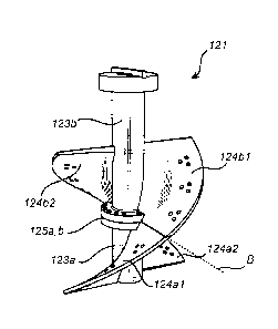
An agitation means according to the invention comprises a screw flight
system 121 which is provided in at least two segments 121a, 121b as shown
in Fig. 3 and Fig. 4. Each segment 121a, 121b comprises at least one screw
flight section 124a1, 124a2, 124b1, 124b2 integral to a shaft section 123a,
123b. A complete screw flight system 121 is formed when the at least two
CA 02968492 2017-05-19
WO 2016/079574
PCT/IB2014/066309
8
segments 121a, 121b are assembled to one another as shown in Fig. 5a and
Fig. 5b.
According to the present invention each segment 121a, 121b with the
at least one screw flight section 124a1, 124a2, 124b1, 124b2 and the shaft
segment 123a,123b are formed into one piece of material by for example
casting, molding and/or forging of steel or ductile iron into the forms as
shown
in Fig. 3 and Fig. 4. Thus, in one segment 121a, 121b, said at least one screw
flight section 124a1, 124a2; 124b1, 124b2 is an integral part of said shaft
section 123a; 123b.
As shown here in the Figures and as disclosed above, said at least two
segments 121a, 121b are, when on site of the mining operation, assembled to
form the screw flight system 121. However, depending on the height of the
vertical grinding mill 1 and the width thereof, said screw flight system 121
may
be segmented into more than two different segments 121a, 121b.
The at least two segments 121a, 121b of the screw flight system 121
are in one embodiment assembled by placing one over the other, with
mutually facing bolting arrangement flanges 125a, 125b and then bolting the
two segments together with bolt and nut. However, other alternatives for
assembling of the two different segments are possible, such as with bolt and
tapped hole, threaded stud and nut, pins, threaded shaft connection, and
clamping.
Further the shaft sections 123a, 123b may also be welded together
after having been placed on top of each other for the assembling of the screw
flight system 121.
In one embodiment, when the assembling of the screw flight system
121 is being made, said at least one screw flight section 124a1, 124a2 on one
segment 121a is arranged such that it together with corresponding at least
one screw flight section 124b1, 124b2 on an adjacent segment 121b provides
a continuous helical screw around the assembled shaft sections 123a, 123b.
Thus, a radially extending upper edge 134a1, 134a2 of a screw flight section
124a1, 124a2 of a first screw flight segment 121a is arranged to abut a
radially extending lower edge 134b1, 134b2 of a second screw flight section
124b1, 124b2 to form a continuous helical screw flight along the assembled
CA 02968492 2017-05-19
WO 2016/079574
PCT/IB2014/066309
9
shaft sections 123a, 123b. In the radially extending boundary B where the two
screw flight sections 124a1, 124a2, 124b1, 124b2 from the two segments
121a, 121b abut may have at least one bolting arrangement edge 134a1,
134a2, 134b1, 134b2 for assembling the corresponding screw flight sections
124a1, 124a2, 124b1, 124b2 at the radially extending boundary B, as shown
in Fig 5b, where holes for bolting is arranged in the edges 134a1 and 134b1,
and also in the (hidden) edges 134a2 and 134b2. However, the edges 134a1,
134a2, 134b1, 134b2 of the two adjacent screw flight sections 124a1, 124a2,
124b1, 124b2 may also, in an alternative embodiment be welded together, as
shown in Fig. 5a.
In another embodiment, no fastening with bolting or welding is used
for the boundary B of the two screw flight sections 124a1, 124a2, 124b1,
124b2. Instead the edges 134a1, 134a2, 134b1, 134b2 are provided with
fitting arrangement with a close fit, to keep the two screw flight sections
124a1, 124a2, 124b1, 124b2 together, like with a groove and tongue fitting.
In the embodiment shown in Fig. 3 and Fig. 4, each screw flight section
124a1, 124a2, 124b1, 124b2 in each segment 121a, 121b is formed in such a
manner that a lower end of each screw flight section 124a1, 124a2, 124b1,
124b2 is positioned circumferentially shifted about 90 from an upper end of
said each screw flight section 124a1, 124a2, 124b1. However,
circumferentially shifting up to 180 is also possible depending on the size
of
the agitator means 12 when assembled.
In Fig. 6 an agitator means 12 according to one embodiment of the
invention is shown. The agitator means 12 comprises the inner screw flight
system 121 assembled by the two screw flight system segments 121a, 121b.
Wear lining elements 122 are arranged and supported on the screw flight
sections 124a1, 124a2, 124b1, 124b2 of the inner screw flight system 121. In
one embodiment the wear lining elements 122 are bolted onto the screw flight
sections 124a1, 124a2, 124b1, 124b2 with bolts and nuts, but may in another
embodiment be welded thereon.
In even another embodiment, the two edges 134a1, 134a2, 134b1,
134b2 of the radially extending boundary B where two screw flight sections
124a1, 124a2, 124b1, 124b2 from the two segments 121a, 121b abut are
CA 02968492 2017-05-19
WO 2016/079574 PCT/IB2014/066309
only positioned in closed contact, and then the two sections are bridged by
the use of overlaying wear lining elements, which are positioned such that
said boundary B between the sections 124a1, 124a2, 124b1, 124b2 are
covered, bridged and/or overlapped.
5 In another embodiment of the present invention, the bolting
arrangement flanges on the assembled shaft may be protected by sheet
metal.
The skilled person realises that a number of modifications of the
embodiments described herein are possible without departing from the scope
10 of the invention, which is defined in the appended claims.
The agitator means of the invention is equally applicable to different
materials to be ground, such as ore.
In the drawings, a vertically arranged stirred mill is shown. However,
the invention may also be applied to stirred mills oriented in other
directions.