Note: Descriptions are shown in the official language in which they were submitted.
MOTOR POWER SECTION WITH INTEGRATED SENSORS
Cross Reference to Related Applications
[0001] This application claims priority from U.S. provisional application
number
62/342,842, filed May 27, 2016.
Technical Field/Field of the Disclosure
[0002] The present disclosure relates generally to a motor power section, in
particular a
motor power section with integrated sensors.
Background of the Disclosure
[0003] Accurately determining the position and orientation of a drilling
assembly during
drilling operations may be desirable, particularly when drilling deviated
wells. Traditionally, a
combination of sensors is used to measure downhole trajectory and subterranean
conditions.
Data collected in this fashion is traditionally transmitted to the surface via
MWD telemetry.
Many factors may combine to unpredictably influence the trajectory of a
drilled borehole.
Accurate determination of the borehole trajectory may be used to determine the
position of the
borehole and to guide the borehole to its geological objective as well as
avoiding collisions with
underground objects, geological features, wells, or zones. In other cases, it
is desired to intercept
underground objects, geological features, wells, or zones.
[0004] In some instances, surveying of a borehole using conventional methods
involves the
periodic measurement of the Earth's magnetic and gravitational fields to
determine the azimuth
and inclination of the borehole at the bottom hole assembly. In some
instances, the distance,
orientation, or both the distance and orientation of a borehole relative to
other boreholes is
determined by periodically or continuously measuring the magnetic field that
is produced
1
Date Recue/Date Received 2022-07-20
CA 2968574 2017-05-26
either passively from the adjacent wellbore's casing or drillpipe or by
measuring an actively
generated magnetic field.
[0005] As the wellbore is drilled, the greater the distance between the drill
bit and sensors,
commonly known as a MWD package, the longer it takes for any changes in the
azimuth,
inclination, relative distance, or relative orientation of the wellbore at the
drill bit to be
recognized by an operator. In some bottom hole assemblies, some equipment used
in the
bottom hole assembly, such as a mud motor, may move traditional MWD packages a
long
distance from the drill bit, and thus delay feedback or impede accuracy on
azimuth and
inclination data of the wellbore. Typically, a mud motor may include a power
section including
a stator and rotor. The stator typically includes a thin housing and an
elastomeric stator insert.
Summary
[0006] The disclosure includes a power section for a bottom hole assembly for
use in a
wellbore. The power section includes a stator, the stator including a housing,
and a stator
insert. The power section further includes a rotor, the rotor rotatable
eccentrically within the
stator. In addition, the power section includes a sensor package, the sensor
package integrated
into the power section.
[0007] The disclosure includes a power section for a bottom hole assembly for
use in a
wellbore. The power section includes a stator, the stator including a housing,
a stator insert,
and a payload housing. The payload housing is positioned on an outer surface
of the housing,
and the payload housing includes a payload pocket. The power section further
includes a rotor,
the rotor rotatable eccentrically within the stator.
2
[0007a] The disclosure also provides a bottom hole assembly for use in
a wellbore, the
bottom hole assembly comprising a power section, the power section including:
a stator, the
stator having a stator housing, a stator insert, and a payload housing, the
payload housing fixedly
positioned on an outer surface of the stator housing, the outer surface of the
stator housing
exposed to the wellbore and forming a continuous cylindrical outer surface,
the stator insert
positioned within the stator housing, the payload housing extending radially
outward beyond
the greatest radius of the stator housing, the payload housing including a
payload pocket,
whereby the payload housing extends radially outward beyond the outer surface
of the stator
housing, wherein the payload housing is at a same longitudinal position on a
tool string as the
stator insert; a sensor package positioned at least partially within the
payload housing; and a
rotor, the rotor rotatable eccentrically within the stator. The bottom hole
assembly further
comprises: a flex shaft, the flex shaft mechanically coupled to the rotor and
rotatable by the
rotor; an intermediate shaft, the intermediate shaft positioned within the
stator housing and
mechanically coupled to the flex shaft, and the intermediate shaft rotatable
concentrically with
the stator housing; a bent sub, the bent sub mechanically coupled to the
stator housing and
having a bend that defines a bend direction; a bit shaft, the bit shaft
mechanically coupled to the
intermediate shaft; and a drill bit, the drill bit mechanically coupled to the
bit shaft. The payload
housing is positioned on the stator housing so as to be aligned with the bend
direction.
[0007b] The disclosure also provides a bottom hole assembly for use in
a wellbore, the
bottom hole assembly comprising a power section, the power section including:
a stator, the
stator having a stator housing, a stator insert, and a payload housing, the
payload housing fixedly
positioned on an outer surface of the stator housing, the outer surface of the
stator housing
2a
Date Recue/Date Received 2023-08-24
exposed to the wellbore and forming a continuous cylindrical outer surface,
the stator insert
positioned within the stator housing, the payload housing extending radially
outward beyond
the greatest radius of the stator housing, the payload housing including a
payload pocket,
whereby the payload housing extends radially outward beyond the outer surface
of the stator
housing, wherein the payload housing is at a same longitudinal position on a
tool string as the
stator insert; a sensor package positioned at least partially within the
payload housing; and a
rotor, the rotor rotatable eccentrically within the stator. The bottom hole
assembly further
comprises: a flex shaft, the flex shaft mechanically coupled to the rotor and
rotatable by the
rotor; an intermediate shaft, the intermediate shaft positioned within the
stator housing and
mechanically coupled to the flex shaft, and the intermediate shaft rotatable
concentrically with
the stator housing; a bent sub, the bent sub mechanically coupled to the
stator housing and
having a bend that defines a bend direction; a bit shaft, the bit shaft
mechanically coupled to the
intermediate shaft; and a drill bit, the drill bit mechanically coupled to the
bit shaft. The payload
housing is positioned on the stator housing so as to be aligned opposite to
the bend direction.
[0008] The disclosure also provides a bottom hole assembly for use in a
wellbore. The
bottom hole assembly includes a power section. The power section includes a
stator, the stator
having a housing, a stator insert, and a payload housing. The payload housing
is positioned on
an outer surface of the housing and the payload housing includes a payload
pocket. The power
section also includes a rotor, the rotor rotatable eccentrically within the
stator. The bottom hole
assembly also includes a flex shaft, the flex shaft mechanically coupled to
the rotor and rotatable
by the rotor. In addition, the bottom hole assembly includes an intermediate
shaft, the
intermediate shaft positioned within the housing and mechanically coupled to
the flex shaft.
2b
Date Recue/Date Received 2023-08-24
The intermediate shaft is rotatable concentrically with the housing. The
bottom hole assembly
includes a bent sub, the bent sub mechanically coupled to the housing, and a
bit shaft, the bit
shaft mechanically coupled to the intermediate shaft. In addition, the bottom
hole assembly
includes a drill bit, the drill bit mechanically coupled to the bit shaft.
Brief Description of the Drawings
[0009] The present disclosure is best understood from the following
detailed description
when read with the accompanying figures. It is emphasized that, in accordance
with the standard
practice in the industry, various features are not drawn to scale. In fact,
the dimensions of the
various features may be arbitrarily increased or reduced for clarity of
discussion.
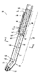
[0010] FIG. 1 depicts an elevation view of a bottom hole assembly having a
motor power
section with integrated sensor package consistent with at least one embodiment
of the present
disclosure.
[0011] FIG. 2 depicts a cross section view of the bottom hole assembly
of FIG. 1.
[0011a] FIG. 2A depicts a view in section along lines 2A-2A of the
bottom hole assembly
of FIG. 2.
3
Date Recue/Date Received 2023-08-24
CA 2968574 2017-05-26
[0012] FIG. 3 depicts a partial cutaway view of the bottom hole assembly of
FIG. 1.
[0013] FIG. 4 depicts a partial cross section view of the bottom hole assembly
of FIG. 1.
[0014] FIG. 5 depicts a schematic view of a MWD package consistent with at
least one
embodiment of the present disclosure.
Detailed Description
[0015] It is to be understood that the following disclosure provides many
different
embodiments, or examples, for implementing different features of various
embodiments.
Specific examples of components and arrangements are described below to
simplify the
present disclosure. These are, of course, merely examples and are not intended
to be limiting.
In addition, the present disclosure may repeat reference numerals and/or
letters in the various
examples. This repetition is for the purpose of simplicity and clarity and
does not in itself
dictate a relationship between the various embodiments and/or configurations
discussed.
[0016] In some embodiments of the present disclosure as depicted in FIG. 1,
bottom hole
assembly (BHA) 101 may include mud motor 103, having power section 106. BHA
101 may
include drill bit 113. In some embodiments, BHA 101 may include bent sub 115.
Although
depicted and described herein as utilizing bent sub 115, one having ordinary
skill in the art
with the benefit of this disclosure will understand that BHA 101 may not
include bent sub 115.
In some embodiments, one or more wear pads or knots (not shown) may be
positioned on an
exterior surface of BHA 101, such as on an outer surface of power section 106.
[0017] In some embodiments, as depicted in FIG. 2, power section 106 may
include stator 105
and rotor 107. Stator 105 may include housing 120 and stator insert 122.
Stator insert 122 may,
4
CA 2968574 2017-05-26
in some embodiments, be formed from rubber and may be cast onto the inner
surface of
housing 120. Rotor 107 may rotate eccentrically within stator insert 122 of
stator 105 as fluids
are pumped through mud motor 103. In some embodiments, rotor 107 of power
section 106
may be mechanically coupled by flex shaft 109 to intermediate shaft 111. Flex
shaft 109 may
serve to transmit rotational force between rotor 107 and intermediate shaft
111 and allow the
eccentric movement of rotor 107 within stator 105 to be translated into the
concentric rotation
of intermediate shaft 111. Intermediate shaft 111 may, in some embodiments,
transmit
rotational force between mud motor 103 and drill bit 113. As understood in the
art, one or more
additional assemblies may be included in BHA 101 including, for example and
without
limitation, bent sub 115. In some embodiments, drill bit 113 may be
mechanically coupled to
bit shaft 117 which may be mechanically coupled to intermediate shaft 111 by,
for example
and without limitation, CV joint or knuckle joint 119.
[0018] In some embodiments, intermediate shaft 111 may be positioned within
housing 120. In
some embodiments, intermediate shaft 111 may be supported within housing 120
by one or
more bearings, depicted in FIG. 2 as upper bearing 121 and lower bearing 123.
Housing 120
may couple between mud motor 103 and any additional components of BHA 101 such
as, for
instance and without limitation, bent sub 115. Although discussed with a
particular
configuration of BHA 101, one having ordinary skill in the art with the
benefit of this
disclosure will understand that the specific configuration described and
depicted herein is not
intended to be limiting, and any suitable configuration of BHA 101 may be
utilized without
deviating from the scope of this disclosure. For example and without
limitation, in some
embodiments, although not depicted, one or more stabilized bearing housings or
slick bearing
housings may be included within BHA 101.
[0019] In certain embodiments of the present disclosure, sensors,
including, but not limited
to MWD or logging while drilling (LWD) sensors may be integrated into power
section 106. In
some embodiments, stator 105 may include payload pocket 143 into which
sensors, such as
MWD or LWD sensors may be positioned. In some embodiments, payload pocket 143
may be
positioned within housing 120. In some embodiments, payload pocket 143 may be
formed
entirely within housing 120. In some embodiments, payload pocket 143 may be a
cavity or
recess formed in housing 120. In some embodiments, payload pocket 143 may be
rotationally
aligned with a toolface TF of BHA 101 as shown in FIG. 2A. As used herein,
toolface refers to
a rotational reference point along BHA 101. For example and without
limitation, toolface may,
in some embodiments, refer to the direction in which bent sub 115 is offset.
In some
embodiments, payload pocket 143 may be rotationally aligned opposite the
toolface TF of BHA
101. In some embodiments, the rotational orientation of payload pocket 143 may
be adjusted
by, for example and without limitation, the inclusion of one or more shims in
one or more
threaded connections or by cutting the threads of the threaded connections to
result in the desired
alignment.
[0020] In some embodiments, one or more additional components of power
section 106
may at least partially form payload pocket 143. For example, in some
embodiments, sleeve 101a
may be threadedly coupled within housing 120 and payload pocket 143 may be at
least partially
positioned within the sleeve. In some embodiments, payload pocket 143 may be a
recess formed
in the outer surface of housing 120. In some such embodiments, a hatch cover
may be hingedly
or removably coupled to housing 120 and positioned to close the recess while
6
Date Recue/Date Received 2023-08-24
CA 2968574 2017-05-26
allowing selective access thereto. In some embodiments, BHA 101 may include
more than one
payload pocket 143. In some embodiments, one or more wireways may be formed in
housing
120. The wireways may be formed such that wires may extend between payload
pockets 143 or
between payload pockets 143 and other components of BHA 101. In certain
embodiments,
wireways may be formed in payload housing 141.
[0021] In some embodiments, BHA 101 may include payload housing 141. Payload
housing
141 may be positioned on an outer surface of power section 106 as discussed
further herein
below. In some embodiments, payload pocket 143 may be positioned at least
partially within
payload housing 141. In some embodiments, payload housing may be positioned on
an exterior
surface of stator 105. In some embodiments, payload housing 141 may be
mechanically
coupled to stator 105. In some embodiments, payload pocket 143 may be an open
area within
which one or more downhole sensors may be positioned. For example, in some
embodiments,
sensor package 125 may be positioned within payload pocket 143. Sensor package
125 may
include any downhole sensors, downhole measurement, or downhole telemetry
equipment
including one or more of an MWD or LWD system. As depicted in FIGS. 3 and 4,
payload
pocket 143 may include one or more openings into which sensor package 125 may
be
positioned.
[0022] In some embodiments, as depicted in FIG. 4, payload housing 141 may
include wear
pad 145. Wear pad 145 may be positioned on an exterior surface of payload
housing 141. Wear
pad 145 may, for example and without limitation, protect payload pocket 143
from the
downhole environment, including abrasive materials and formations encountered
during
drilling operations. In some embodiments, as depicted in FIG. 3, payload
housing 141 may
7
CA 2968574 2017-05-26
include end plate 147. In some embodiments, end plate 147 may be removable
from payload
housing 141 to, for example and without limitation, allow access to payload
pocket 143.
[0023] In some embodiments, as depicted schematically in FIG. 5, sensor
package 125 may
include one or more sensors which may be positioned within payload pocket 143.
The sensors
may include, for example and without limitation, one or more magnetometers
127,
accelerometers 129, gyros 131, temperature sensors 133, formation resistivity
sensors 155, and
gamma radiation detectors 157. As understood in the art, magnetometers 127,
accelerometers
129, and gyros 131 may include multiple sensors to measure parameters in more
than one axis,
including, without limitation, in three orthogonal directions, commonly known
as a triaxial
arrangement.
[0024] In some embodiments, sensor package 125 may further include processor
135 and
associated memory 137 to gather, receive, store, process, and/or transmit
signals from the
sensors. In some embodiments, processor 135 may receive and process commands.
In some
embodiments, sensor package 125 may be able to gather, receive, store,
process, and/or
transmit, for example and without limitation, one or more of total magnetic
field strength,
inclination, RPM, magnetometer data, accelerometer data, temperature,
formation resistivity,
gamma count, voltage and current data, date/time, and toolface.
[0025] In some embodiments, sensor package 125 may include power source 139 to
power one
or more of the sensors and processor 135. In some embodiments, power source
139 may
include, for example and without limitation, one or more batteries or
generators. Power source
139 may be integral to sensor package 125 or connected to sensor package 125
via a wire. In
some embodiments, power source 139 may be positioned within payload pocket
143. In some
8
CA 2968574 2017-05-26
embodiments, power source 139 may be electrically coupled to but located apart
from payload
pocket 143.
[0026] In some embodiments, sensor package 125 may include telemetry equipment
142
electronically coupled to processor 135 including, for example and without
limitation, antenna
140, communications transceiver 138, or wired connection through a wireway as
previously
discussed for transmitting or receiving data.
[0027] The foregoing outlines features of several embodiments so that a person
of ordinary
skill in the art may better understand the aspects of the present disclosure.
Such features may
be replaced by any one of numerous equivalent alternatives, only some of which
are disclosed
herein. One of ordinary skill in the art should appreciate that they may
readily use the present
disclosure as a basis for designing or modifying other processes and
structures for carrying out
the same purposes and/or achieving the same advantages of the embodiments
introduced
herein. One of ordinary skill in the art should also realize that such
equivalent constructions do
not depart from the spirit and scope of the present disclosure and that they
may make various
changes, substitutions, and alterations herein without departing from the
spirit and scope of the
present disclosure.
9