Note: Descriptions are shown in the official language in which they were submitted.
SYSTEMS AND METIIODS FOR All-INSIDE SUTURE FIXATION FOR IMPLANT
ATTACI IMENT AND SOFT TISSUE REPAIR
(00011
FIELD OF THE INVENTION
[0002] The present invention relates generally to a system and method for
reducing or
bringing into close approximation, generally referred to as re-approximation
herein, pieces
of torn or damaged soft tissue to facilitate tissue repair and healing, and/or
for attaching an
implant during soft tissue repair. such as in meniscal repair or replacement.
More
particularly, the present invention relates to a system and method for an all-
inside suture
fixation device and method designed for the placement of surgical anchors.
BACKGROUND OF THE INVENTION
[0003] There are current instruments and systems on the market for use in
repairing torn or
damaged soft tissue, such as a torn meniscus. However, such devices have
various
drawbacks. For example, current systems on the market utilize needles and
implants that
have a comparatively large cross-section which damage the tissue during
implantation.
Further, such systems can be difficult to use in that an operator, such as a
surgeon, must
utilize higher forces than should be required to position the needle and
implant the anchors.
Such systems include the FAST-FIXIN1 and RAPIDLOC I'm.
100041 Similarly, such devices are used in procedures for surgical attachment
of a soft tissue
implant in a joint, such as an autograft, allograft, or xenograft tissue or
other compatible
tissues and/or devices. Such implants may be bioresorbable and/or non-
resorbable, synthetic
and/or non-synthetic. One example of a bioresorbablc implant is the CMITm(Ivy
Sports
Medicine I,I,C (a division of Stryker Orthopedics), Redwood City, CA), a
collagen-based
meniscus implant. the surgical attachment of which can involve techniques that
are difficult
to master. The above-mentioned systems similarly have limitations in these
procedures
because, in their delivery of anchors to attach an implant to the meniscal
rim, they may cause
unnecessary destruction to the implant. The needle used to pass the anchor
through an
- l -
CA 2968651 2018-11-07
CA 2968651 2017-05-25
SYKSM 3.0E-1006
implant and through the meniscal rim punctures the implant in a manner that
may lead to
tearing of the implant matrix.
[0005] There is a need, therefore, for a dimensionally smaller device that
employs a needle
and anchors that are less destructive on surrounding tissue and/or an implant,
if present.
Further, there is a need for a system that is more user-friendly and adaptable
for each
surgeon's particularities and surgical setup.
BRIEF SUMMARY OF THE INVENTION
[0006] One embodiment of the present invention includes a system for repairing
a meniscus,
including a suture assembly including a first anchor, a second anchor, and a
length of suture
connecting the first anchor and the second anchor, the suture including a
slide knot along its
length between the first anchor and the second anchor, and an inserter, the
inserter including
a needle having a longitudinal extending bore and an open distal end, the bore
being
configured to receive the first anchor and the second anchor, a housing
operatively connected
to a proximal end of the needle, the housing having a lumen and a slot, the
slot including a
first portion, a second portion, a first shoulder and a second shoulder, and a
pusher configured
to rotate and slide within the lumen of the housing and the longitudinal
extending bore of the
needle, the pusher having an extension extending through the slot and
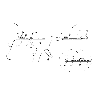
configured to be
maneuverable through the first portion and second portion and engageable with
the first
shoulder and second shoulder.
[0007] In another embodiment, the present invention includes an instrument for
repairing a
meniscus including a needle having a longitudinal extending bore and an open
distal end, a
housing operatively connected to a proximal end of the needle, the housing
having a lumen, a
slot including a first portion, a second portion, a first shoulder and a
second shoulder, and a
first grip and a second grip, and a pusher configured to rotate and slide
within the lumen of
the housing and the longitudinal extending bore of the needle, the pusher
having an extension
extending through the slot and configured to be maneuverable through the first
portion and
second portion and engageable with the first shoulder and second shoulder.
[0008] In a further embodiment, the present invention includes a system for
repairing a
meniscus, including a suture assembly including a first anchor, a second
anchor, and a
flexible suture connecting the first anchor and the second anchor, the
flexible suture including
a slide knot between the first anchor and the second anchor, and an inserter,
including a
needle having a longitudinal extending bore and an open distal end, the bore
being configured
to receive the first anchor and the second anchor, a housing operatively
connected to a
-2-
CA 2968651 2017-05-25
SYKSM 3.0E-1006
proximal end of the needle, the housing having a lumen, a pusher configured to
rotate and
slide within the lumen of the housing and the longitudinal extending bore of
the needle, and a
sheath releasably secured to the housing by a press-fit engagement and having
a lumen, the
needle being positionable within the lumen.
BRIEF DESCRIPTION OF THE DRAWINGS
[0009] Features of the invention are shown in the drawings, in which like
reference numerals
designate like elements. The drawings form part of this original disclosure,
in which:
[0010] FIG. 1 is a side view of an embodiment of a system for all-inside
suture fixation for
implant attachment and soft tissue repair of the present invention;
[0011] FIG. 2 is a top view of an embodiment of a needle of the system of FIG.
1;
[0012] FIG. 3 is a side view of the needle of FIG. 2;
[0013] FIG. 4 is a cross-sectional view taken along line 4-4 in FIG. 2;
[0014] FIG. 5 is a side view of another embodiment of the needle for the
system of FIG. 1;
[0015] FIG. 6 is atop view of the needle of FIG. 5;
[0016] FIG. 7 is a cross-sectional view taken along line 7-7 in FIG. 6;
[0017] FIG. 8 is a side view of a pusher of the system of FIG. 1;
[0018] FIG. 9 is a top view of an anchor of a suture of the system of FIG. 1;
[0019] FIG. 10 is an end view of the anchor of FIG. 9;
[0020] FIG. 11 is a side view of the anchor of FIG. 9;
[0021] FIG. 12 is a top view of another embodiment of an anchor of the suture
for the system
of FIG. 1;
[0022] FIG. 13 is an end view of the anchor of FIG. 12;
[0023] FIG. 14 is a side view of the anchor of FIG. 12;
[0024] FIG. 15 is a view of an anchor threaded onto a suture of the system of
FIG. 1;
[0025] FIG. 16 is a view of the anchor and suture of FIG. 15 with a loop and a
self-locking
slide knot formed in the suture;
[0026] FIG. 17 is a view of the anchor and suture of FIG. 16 with a second
anchor positioned
on the suture;
[0027] FIG. 18 is a partial view of the second anchor and suture of FIG. 17;
[0028] FIG. 19 is a partial view of the second anchor and suture of FIG. 17
with a needle
threaded on the suture;
[0029] FIG. 20 is a partial view of the needle threaded on the suture and
passing through the
center of the suture at the second anchor;
-3-
CA 2968651 2017-05-25
SYKSM 3.0E-1006
[0030] FIG. 21 is a partial view of the needle passing through the center of
the suture at the
second anchor a second time;
[0031] FIG. 22 is a view of the anchor with a knot securing it to the suture;
[0032] FIG. 23 is a partial view of the suture and the second anchor at one
end thereof:
[0033] FIG. 24 is a perspective view of a meniscus with an implant positioned
on the
meniscus;
[0034] FIG. 25 is a view of the implant after it has been secured to the
remaining surrounding
soft tissue, such as meniscus;
[0035] FIG. 26 is a view of the suture and anchor configuration of the system
of FIG. 1;
[0036] FIG. 27 is a top view of the needle with the pusher extended therefrom;
[0037] FIG. 28 is a side view of the suture being threaded into the pusher and
the needle;
[0038] FIG. 29 is a side view of the suture further being threaded into the
pusher and the
needle;
[0039] FIG. 30 is a top view of the needle with the suture loaded therein;
[0040] FIG. 31 is a side view of the needle of FIG. 30;
[0041] FIG. 32 is a top view of the needle of the system of FIG. 1 piercing
the implant and
meniscus of FIG. 25 at a first location;
[0042] FIG. 33 is a top view of the needle of FIG. 32 after the first anchor
has been deployed
from the needle with the pusher;
[0043] FIG. 34 is a perspective view of the needle of FIG. 32 after it has
been pulled back
through the meniscus and implant;
[0044] FIG. 35 is a top view of the needle of FIG. 32 piercing the implant and
remaining
surrounding soft tissue, such as meniscus, of FIG. 25 at a second location;
[0045] FIG. 36 is a top view of the needle of FIG. 35 after the second anchor
has been
deployed from the needle with the pusher;
[0046] FIG. 37 is a top view of the needle of FIG. 35 after is has been pulled
back through
the meniscus and implant;
[0047] FIG. 38 is a top view of the needle of FIG. 37 with the pusher extended
out of the
needle;
[0048] FIG. 39 is a top view of the needle of FIG. 38 with the pusher pushing
the knot
against the implant;
[0049] FIG. 40 is a top view of the needle of FIG. 39 after it has been pulled
back following
knot pushing and suture tensioning;
-4-
CA 2968651 2017-05-25
SYKSM 3.0E-1006
[0050] FIG. 41 is a side view of the needle of FIG. 40 with the suture exposed
to the needle
cutting surface;
[0051] FIG. 42 is a side view of another embodiment of the needle of FIG. 40
with the suture
exposed to a cutting surface on a cutting sheath;
[0052] FIG. 43 is a top view of the repaired meniscus with the suture tightly
in place;
[0053] FIG. 44 is a side view of another embodiment of a system for all-inside
suture fixation
for implant attachment and soft tissue repair of the present invention;
[0054] FIG. 45 is a proximal end view of a body portion of the system of FIG.
44;
[0055] FIG. 46 is a side view of an embodiment of a pusher of the system of
FIG. 44;
[0056] FIG. 47 is a cross-sectional view of the pusher taken along line 47-47
in FIG. 46;
[0057] FIG. 48A is a side view of a proximal end of the pusher of FIG. 46 in a
first position
relative to the body portion;
[0058] FIG. 48B is the proximal end view of the body portion with a portion of
the pusher in
the first position of FIG. 48A;
[0059] FIG. 48C is a side view of a needle of the system of FIG. 44 and a
distal end of the
pusher, with the pusher in the first position of FIG. 48A;
[0060] FIG. 49A is a side view of the proximal end of the pusher of FIG. 46 in
a second
position relative to the body portion;
[0061] FIG. 49B is the proximal end view of the body portion with a portion of
the pusher in
the second position of FIG. 49A;
[0062] FIG. 49C is a side view of the needle and the distal end of the pusher,
with the pusher
in the second position of FIG. 49A;
[0063] FIG. 50A is a side view of the proximal end of the pusher of FIG. 46 in
a third
position relative to the body portion;
[0064] FIG. 50B is the proximal end view of the body portion with a portion of
the pusher in
the third position of FIG. 50A;
[0065] FIG. 50C is a side view of the needle and the distal end of the pusher,
with the pusher
in the third position of FIG. 50A;
[0066] FIG. 51A is a side view of the proximal end of the pusher of FIG. 46 in
a fourth
position relative to the body portion;
[0067] FIG. 51B is the proximal end view of the body portion with a portion of
the pusher in
the fourth position of FIG. 51A;
-5-
CA 2968651 2017-05-25
SYKSM 3.0E-1006
[0068] FIG. 51C is a side view of the needle and the distal end of the pusher,
with the pusher
in the fourth position of FIG. 51A;
[0069] FIG. 52A is a side view of the proximal end of the pusher of FIG. 46 in
a fifth
position relative to the body portion;
[0070] FIG. 52B is the proximal end view of the body portion with a portion of
the pusher in
the fifth position of FIG. 52A;
[0071] FIG. 52C is a side view of the needle and the distal end of the pusher,
with the pusher
in the fifth position of FIG. 52A;
[0072] FIG. 53A is a side view of the proximal end of the pusher of FIG. 46 in
a sixth
position relative to the body portion;
[0073] FIG. 53B is the proximal end view of the body portion with a portion of
the pusher in
the sixth position of FIG. 53A;
[0074] FIG. 53C is a side view of the needle and the distal end of the pusher,
with the pusher
in the sixth position of FIG. 53A;
[0075] FIGS. 54 and 55 are schematic views showing an embodiment of a system
formed in
accordance with the present invention, wherein the system includes an anchor
assembly and
an inserter.
[0076] FIG. 56 is another illustration of the embodiment of FIGS. 54 and 55
where the
housing of the inserter is transparent for ease of illustration.
[0077] FIGS. 57-59 illustrate a schematic of the distal portion of the
inserter and the anchor
assembly and further wherein portions of the anchor assembly (i.e., the
terminus knot and the
slip knot) are shown in schematic form for clarity of illustration;
[0078] FIGS. 60-70A are schematic views showing further details of the anchor
assembly of
the system of FIGS. 54-59, wherein the terminus knot and the slip knot are
shown in
schematic form in FIG. 60 for clarity of illustration, and further wherein
certain variations of
the terminus knot and the slip knot are shown in line drawings in FIGS. 61, 68-
70 and 68A-
70A;
[0079] FIGS. 71-75 are schematic views showing further details of the inserter
of the system
of FIGS. 54-59, specifically the proximal portions of the inserter;
[0080] FIGS. 76-82 illustrate exemplary uses of the system of FIGS. 54-59.
DETAILED DESCRIPTION
[0081] U.S. Patent Application Serial No. 13/410,501, filed March 2, 2012,
U.S. Patent
Application Serial No. 11/501,235, filed August 9, 2006, U.S. Patent
Application Serial
-6-
No. 11/348,467, tiled February 7, 2006, and U.S. Provisional Patent
Application Serial No.
60/650.131, filed February 7,2005.
10082] A system 1 for repairing soft tissue, such as for example a meniscus,
according to an
embodiment of the present invention is illustrated in FIG. 1. The system 1
includes an
applicator 10 that is constructed and arranged to deploy a suture 12 to soft
tissue, such as the
meniscus. The suture 12 generally includes a flexible length of suture
material 58 and
includes a pair of anchors 60, 70 positioned thereon. The suture 12 will be
discussed in
greater detail below.
100831 The applicator 10 includes a body portion 14 that defines a handle 16
that is
configured to be grasped by the user. The body portion 14 of the applicator 10
receives a
cannula 18 that extends from the body portion 14 in a direction that is away
from the handle
16. The body portion 14 and cannula 18 may be constructed and arranged like
those
described and shown in U.S. Pat. No. 5,928,252. Because the inner workings of
the body
portion 14 are not related to the present invention, they are not described in
detail herein.
100841 The applicator 10 also includes a needle 20 that is connected to a
distal end of the
cannula 18. Of course, the needle 20 may be considered to be a part of the
cannula 18 itself
The needle 20 will be described in greater detail below. The applicator 10
also includes a
pusher 23 that includes a hollow rod 24 that extends through the body portion
14, the cannula
18, and is slidingly received by the needle 20. A knob 26 is attached to one
end of the rod
24 and a spacer 28 with a tab 29 is disposed between the knob 26 and a
proximal end 15 of
the body portion 14 so that the movement of the knob 26 relative to the body
portion 14 and,
hence, movement of the rod 24 relative to the needle 20, may be limited to
prevent premature
deployment of one of the anchors 60 prior to the placement of the other anchor
70, as
described in further detail below. A trigger 30 is connected to and extends
from the body
portion 14, as shown in FIG. 1. The trigger 30 is configured to manually
control the
advancement of the rod 24 within the cannula 18. A side lever 32 is connected
to the body
portion so as to be pivotable thereon. Operation of the side lever 32 will be
discussed in
greater detail below.
100851 As shown in FIG. 1, a depth penetration limiter 21 is placed over the
distal end of the
cannula 18 so as to partially cover the needle 20. The limiter 21 provides the
user with a
visualization of the depth of the needle 20 in the tissue to avoid
neurovascular injury. An
-7-
CA 2968651 2018-11-07
CA 2968651 2017-05-25
SYKSM 3.0E-1006
outer sheath 22 is placed over the limiter 21 to aid in the insertion of the
cannula 18 into the
incision already created in the patient. The outer sheath 22 may be designed
to partially
surround the limiter 21 so that the user may still see at least a portion of
the limiter 21 when
the needle 20 is being inserted into the incision. The outer sheath 22 is
removed by the user
once the cannula 18 has been inserted into the incision site.
[0086] One embodiment of a needle 20a that may be used as the needle 20 in
FIG. 1 is shown
in FIGS. 2-4. As shown, the needle 20a includes a sleeve 34a that is attached
to the cannula
18 at a proximal end. The needle 20a also includes a distal end 36a that is
connected to the
sleeve 34a and is constructed and arranged to be inserted into a meniscus or a
tissue. The
distal end 36a is substantially straight and includes a point 38a for piercing
the meniscus or
tissue and a slot 40a, which allows for the flexible length 58 of the suture
12 to extend out of
the needle 20a. As shown in the Figures, the distal end 36a of the needle 20a
also includes a
cutting surface 37a that is constructed and arranged to cut excess suture 12,
which will be
described in greater detail below.
[0087] As shown in FIGS. 2-4, a cutting sheath 35a that at least partially
surrounds the distal
end 36a may also be provided. In the illustrated embodiment, the cutting
sheath 35a
completely surrounds the circumference of the distal end 36a. In other
embodiments, the
cutting sheath 35a may only partially surround the distal end 36a. The cutting
sheath 35a is
configured to be slidable relative to the distal end 36a so that it may be
moved longitudinally
along the distal end 36a toward the point 38a, and then moved back again
toward the sleeve
34a. The cutting sheath 35a may include a tab that extends outward from the
needle 20a so
that the user may manipulate the cutting sheath 35a via the tab. As shown, the
cutting sheath
35a includes at least one cutting surface 33a that is constructed and arranged
to cut excess
suture 12, which will be described in greater detail below.
[0088] As shown in FIG. 4, the distal end 36a is configured to hold the pair
of anchors 60, 70
of the suture 12. The needle 20a may include a dimple 39a located near the
point 38a to
assist in seating the anchors 60, 70 prior to deployment of the anchors 60, 70
from the needle
20a, as will be described in greater detail below. The needle 20a may be
manufactured from,
for example stainless steel, and is sized to withstand insertion through the
implant and the
meniscus substantially without bending or budding.
[0089] Another embodiment of a needle 20b that may be used as the needle 20 in
the
applicator 10 is shown in FIGS. 5-7. As shown, the needle 20b includes a
sleeve 34b that is
attached to the cannula 18 at a proximal end. The needle 20b also includes a
distal end 36b
-8-
CA 2968651 2017-05-25
SYKSM 3.0E-1006
that is connected to the sleeve 34b and is constructed and arranged to be
inserted into a
meniscus or a tissue. The distal end 36b is curved such that it extends at an
angle a relative
to the sleeve 34b. The angle a may be about 15-45 degrees, and for example,
about
30 degrees. The distal end 36b also includes a point 38b for piercing the
meniscus or tissue
and a slot 40b, which allows for portions of the suture 12 to extend out of
the needle 20b.
The distal end 36b of the needle 20b also includes at least one cutting
surface 37b that is
constructed and arranged to cut excess suture 12.
[0090] As shown in FIGS. 5-7, a cutting sheath 35b that at least partially
surrounds the distal
end 36b may also be provided. In the illustrated embodiment, the cutting
sheath
35b completely surrounds the circumference of the distal end 36b. In other
embodiments, the
cutting sheath 35b may only partially surrounds the distal end 36b. The
cutting sheath 35b is
configured to be slidable relative to the distal end 36b so that it may be
moved longitudinally
along the distal end 36b toward the point 38b, and back again to the sleeve
34b. The cutting
sheath 35b may include a tab that extends outward from the needle 20b so that
the user may
manipulate the cutting sheath 35b via the tab. As shown, the cutting sheath
35b includes a
cutting surface 33b that is constructed and arranged to cut excess suture 12.
[0091] As shown in FIG. 7, the distal end 36b is also configured to hold the
pair of anchors
60, 70. The needle 20b may also include a dimple 39b located near the point
38b to assist in
seating the anchors 60, 70 prior to deployment. Like the needle 20a of FIGS. 2-
4, the needle
20b may be manufactured from, for example, stainless steel, and is sized to
withstand
insertion through the implant and the meniscus substantially without bending
or buckling.
[0092] An embodiment of the pusher 23 is shown in greater detail in FIG. 8.
The rod 24 is
hollow and is configured to receive the flexible length 58 of the suture 12
that extends away
from the needle 20. The knob 26 includes a hole for receiving the rod 24, so
that the flexible
length 58 of the suture 12 may extend through the knob 26 as well. A distal
portion of the
rod 24 includes a pair of slots 42 that are configured to allow the flexible
length 58 of the
suture 12 to be threaded out of the rod 24 via one slot 42 (the distal slot)
and back into the rod
24 via the other slot 42 (the proximal slot), as represented by an exposed
portion 44 of the
flexible length 58 of the suture 12. This threading of the suture 12 properly
aligns the
exposed portion 44 relative to the rod 24 to facilitate the cutting of the
suture 12, which will
be described in further detail below. As shown in FIG. 7, the rod 24 may be
flexible so that it
may be used with the embodiment of the needle 20b described above.
-9-
CA 2968651 2017-05-25
SYKSM 3.0E-1006
[0093] FIGS. 9-11 illustrated an embodiment of an anchor 46 that may be used
as the anchors
60, 70 of the suture 12. As shown, the anchor 46 includes a tab 48 that
extends upward from
a body 50. The body 50 has opposing ends 51 that are substantially
perpendicular to a
longitudinal axis LA of the anchor 46. A hole 52 that is centered on the
longitudinal axis LA
extends through the body 50 and the tab 48 where the body 50 and tab 48 are
connected.
Otherwise, the body 50 includes a hollowed out half-cylinder 53 at portions
where the tab
48 is not connected. The anchor 46 may be made out of any material desired
such as,
polymer, for example polyether ether ketone (PEEK), or a bioabsorbable
polymer, for
example poly(L-lactide).
[0094] Another embodiment of an anchor 54 for use in the suture 12 of the
system 1 is shown
in FIGS. 12-14. As shown, the anchor 54 is a solid rod with a pair of holes 56
that extend
substantially perpendicularly through the longitudinal axis of the rod. The
holes 56 are sized
to receive a flexible portion of the suture 12. A recessed channel 57 is
located between the
holes 56 to seat the flexible length 58 of the suture 12. Like the anchor 46,
the anchor
54 may be made out of any material desired such as, polymer, for example
polyether ether
ketone (PEEK), or a bioabsorbable polymer, for example poly(L-lactide).
[0095] In another embodiment of an anchor that may be used as one or both of
the anchors
60, 70 of the suture 12, the anchor may include at least one barb that is
formed from or
connected to a main body portion of the anchor. The barb may be constructed
and arranged
to be biased to an orientation in which a free end of the barb extends away
from the body, yet
is oriented such that the free end is near the body when suitable pressure is
applied to the
barb. The use of such an anchor with the system 1 will be described in greater
detail below.
[0096] Unless otherwise indicated herein, further discussions of the anchors
60, 70 will be
for the anchor 46 illustrated in FIGS. 9-11, although it is understood that
the anchor 54 of
FIGS. 12-14 may be used with slight modifications to the language used to
describe the
assembly of the suture 12. Such modifications would be readily appreciated by
one of skill in
the art and are therefore not described herein.
[0097] FIGS. 15-23 show the various stages of an embodiment of assembling the
suture 12 of
the system 1 of FIG. 1. FIG. 15 shows the flexible length 58 of the suture 12
with one anchor
60 threaded thereon. FIG. 16 shows a loop 62 and a knot 64 that closes the
loop 62, with the
anchor 60 being located within the loop 62. The knot 64 may be a self-locking
slide knot.
Methods for tying a self-locking slide knot are described in, for example, "A
New Clinch
Knot," Weston, P. V., Obstetrics & Gynecology, Vol. 78, pp. 144-47 (1991);
"Physical
-10-
Properties of Self Locking and Conventional Surgical Knots," Israelsson, F.
A., et al.,
European Journal of Surgery, Vol. 160, No. 6-7, pp. 323-27 (1994); "Nicky's
Knot--A New
Slip Knot for Arthroscopic Surgery," De Beer, J. F., et at., Arthroscopy: The
Journal of
Arthroscopic and Relate Surgery, Vol. 14, No 1, pp. 109-110 (1998); "The Giant
Knot: A
New One-Way Self-Locking Secured Arthroscopic Slip Knot," Fleega, B. A., et
at.,
Arthroscopy: The Journal of Arthroscopic and Relate Surgery, Vol. 15, No 4,
pp. 451-52
(1999); "Arthroscopic Knot Tying Techniques," Nonage, W. M., et al.,
Arthroscopy: The
Journal of Arthroscopic and Relate Surgery, Vol. 15, No 5, pp. 515-521 (1999);
"The SMC
Knot--A New Slip Knot With Locking Mechanism," Kim, S., et al., Arthroscopy:
The
Journal of Arthroscopic and Relate Surgery, Vol. 16, No 5, pp. 563-65 (2000);
"Technical
Note: A 'New' Arthroscopic Sliding Knot," Field, M. H., et at., Orthopedic
Clinics of North
America, Vol. 32, No. 3, pp. 525-26 (2001); "Arthroscopic Knot Tying," Kim,
S., et at.,
Techniques in Shoulder & Elbow Surgery, Vol. 4, No. 2, pp. 35-43 (2003); "The
PC Knot:
A Secure and Satisfying Arthroscopic Slip Knot," Pallia, C. S., Arthroscopy:
The Journal of
Arthroscopic and Relate Surgery, Vol. 19, No 5, pp. 558-560 (2003); and "The
Tuckahoc
Knot: A Secure Locking Slip Knot," Wiley, W. 13., et al., Arthroscopy: The
Journal of
Arthroscopic and Relate Surgery, Vol. 20, No 5, pp. 556-59 (2004),
100981 Once the self-locking slide knot 64 has been tied, another anchor 70 is
slid onto the
flexible length 58 until it is located approximately 7 mm from the knot 64, as
shown in
FIG. 17 (note that the Figures are not necessarily drawn to scale). This
distance is only meant
to be an example and is not intended to be limiting in any way. The flexible
length 58 of the
suture 12 is tied off with one hitch knot 74 on the anchor 70, as shown in
FIG. 18.
100991 Next, as shown in FIG. 19, a needle 72 is threaded with the remainder
of the flexible
length 58. The end of the flexible length 58 with the needle 72 is passed
through the center
of the suture of the hitch knot twice to hold the hitch knot 74 in place, as
shown in FIGS. 20
and 21. As shown in FIG. 22, the excess flexible length 58 is cut, leaving
approximately
2 mm as a tail. Finally, as shown in FIG. 23, the tip of the flexible length
58 may be melted
to prevent fraying of the suture 12. An assembled suture 12 before it is
loaded into the
applicator 10 is shown in FIG. 26.
101001 FIG. 24 shows a damaged meniscus 80 having a rim 81, and an implant 82
positioned
adjacent the damaged part of the meniscus 80. The implant 82 may be any type
of implant
82 suitable for such meniscus repair. For example, the implant 82 includes
collagen. In an
-11-
CA 2968651 2018-11-07
CA 2968651 2017-05-25
SYKSM 3.0E-1006
embodiment, the implant 82 includes the CMI, a collagen-based meniscus
implant. The
implant 82 illustrated in the Figures has already been cut to the appropriate
size. Both ends
of the implant 82 may be temporarily stapled or sutured using conventional
means to hold the
implant 82 in place while it is being secured to the meniscus 80. FIG. 25
shows a pair of
staples 84, or sutures, holding the implant 82 in place.
[0101] To load the suture 12 into the applicator 10, the cannula 18, with the
needle 20a
attached, is inserted into the body portion 14 of the applicator 10. In this
embodiment, the
needle 20a of FIGS. 2-4 is shown. However, it is understood that the needle
20b may also be
used in the same way. The illustrated and described embodiments are not
intended to be
limiting in any way. While holding down the side lever 32 with a finger or a
thumb, the rod
24 of the pusher 23 is inserted by the user into the proximal end 15 of the
body portion
14 until the end of the rod 24 extends past the point 38a of the needle 20a
with the slots
42 facing upward, as shown in FIG. 27.
101021 Next, as shown in FIG. 28, an end 59 of the suture 12 that is opposite
the anchor 70 is
threaded though the rod 24 of the pusher 23 at the distal end 36a of the
needle 20a. The end
59 of the suture 12 is laced through the distal end of the rod 24, pulled out
of the rod 24 at the
distal slot 42, threaded back into the rod 24 at the proximal slot 42, thereby
leaving the
exposed portion 44 outside of the rod 24. The end 59 of the suture 12 may
extend several
inches outside the pusher 23 beyond the proximal end 15 of the body portion 14
of the
applicator 10 so that the user may grasp the suture 12 during the implant
attachment
procedure, which will be described below. Once the suture 12 has been loaded
into the
applicator 10, the user then presses the side lever 32 and retracts the pusher
23 back into the
needle 20a, as shown in FIG. 29, to locate the slots 42 and the exposed
portion 44 of the
suture 12 before the proximal end of the needle slot 40a, as shown in FIG. 30.
The anchor
60 is inserted into the distal end 36a of the needle 20a, and is followed by
the anchor 70, as
shown in FIGS. 30 and 31. The end 59 of the flexible length 58 that extends
out of the
pusher 23 at the proximal end 15 of the body portion 14 of the applicator 10
may be pulled so
that the knot 64 is generally located on a side of the anchor 60 that is
opposite the other
anchor 70, as shown in FIG. 31 After the anchors 60, 70 are loaded into the
cannula 18, a
portion of the flexible length 58 may extend outside of the cannula 18 via the
slot 40a of the
needle 20a, as shown in FIGS. 30 and 31. ln this arrangement, the pulling of
the trigger
30 causes the anchor 70, the anchor 60, and the knot 64 to be deployed in that
order.
-12-
CA 2968651 2017-05-25
SYKSM 3.0E-1006
[0103] Once the system 1 is assembled, the user places the spacer 28 between
the knob
26 and the proximal end 15 of the body portion 14 so that the advancement of
the anchor
60 will be limited until the placement of the anchor 70 is complete. The user
then inserts the
depth penetration limiter 21 and the outer sheath 22 over the distal end of
the cannula 18 so
as to cover the needle 20 during insertion of the needle 20 into the incision
site. Once the
needle 20 has been inserted into the incision site, the outer sheath 22 may be
removed from
the cannula 18. Of course, the use of the spacer 28, the outer sheath 22, and
the depth
penetration limiter 21 should be considered optional. The illustrated
embodiment is not
intended to be limiting in any way.
[0104] The user may then advance the anchors 60, 70 until the anchor 70 is
located near the
point 38a of the needle 20a, without extending out of the needle 20a. The
dimple 39a may be
used to assist with the placement of the anchor 70. In embodiments where the
dimple 39a is
used, the user should feel a slight resistance to the advancement of the
anchor 70, which
signals the user to stop advancing the pusher 23. Of course, the use of the
dimple 39a should
be considered to be optional. The illustrated embodiment is not intended to be
limiting in any
way.
[0105] While griping the handle 16 and the trigger 30 on the applicator 10,
the user inserts
the needle 20a into a patient at an incision site so that the needle 20a may
then be inserted
through the implant 82 and through the meniscus 80 at a first location 86, for
example near
the center of the implant 82, to a side opposite the insertion site, as shown
in FIG. 32. The
user should be sure that the hitch knot 74 on the anchor 70 has passed through
the meniscus
80, as shown in FIG. 32. In an embodiment, the user then advances the pusher
23 via the
trigger 30 until the anchor 70 is pushed outside the needle 20a, as shown in
FIG. 33. The
user should be careful to not advance the pusher 23 further to avoid the
premature
deployment of the anchor 60. The use of the spacer 28 assists in preventing
the premature
deployment of the anchor 60. In addition to, or in lieu of the spacer 23, the
dimple 39a that is
located near the point 38a of the needle 20a may also be used to provide the
user with tactile
feedback that the anchor 60 has been advanced to its proper pre-deployment
position.
[0106] As shown in FIG. 34, the user then retracts the needle 20a slowly from
the meniscus
80 and the implant 82, leaving the anchor 70 behind on the opposite side of
the meniscus 80.
The anchor 60 will remain inside the needle 20a. If the user hasn't already
done so, the user
next advances the anchor 60 until the anchor 60 is located near the point 38a
of the needle
-13-
CA 2968651 2017-05-25
SYKSM 3.0E-1006
20a. Again for embodiments that include the dimple 39a, the dimple 39a may be
used to
guide the user to correctly position the anchor 60.
[0107] While gripping the handle 16 and the trigger 30 on the applicator 10,
the user inserts
the needle 20a though the implant 82 and through the meniscus 80 at a second
location 88,
which may be for example near the first location 86, until the center of the
anchor 60 is
outside the opposite side of the meniscus 80, as shown in FIG. 35. If the user
hasn't already
done so, the user next removes the spacer 28 from the rod 24 by grasping the
tab 29 and
pulling the spacer 28 away from the rod 24. The user then advances the pusher
23 until the
anchor 60 is pushed outside the needle 20a, as shown in FIG. 36. The user then
retracts the
needle 20a, thereby leaving the anchor 60 on the opposite side of the meniscus
80, as shown
in FIG. 37.
[0108] Having deployed both anchors 60, 70, the user may then advance the
pusher 23 via
the trigger 30 so that the rod 24 extends approximately 1 cm beyond the point
38a of the
needle 20a, as shown in FIG. 38. While gripping the handle 16 and the trigger
30 of the
applicator 10, the user then holds the tip of the rod 24 against the knot 64
and pushes the knot
64 to the surface of the implant 82, being careful not to push the knot 64
through the implant
82. The user continues to grip the handle 16 and the trigger 30 while gently
pulling on the
end 59 of the flexible length 58 of the suture 12 at the proximal end 15 of
the body portion
14 of the applicator 10 until slack in the suture 12 is taken up, and the
anchors 60, 70 sit flat
against the meniscus 80, as shown in FIGS. 39 and 40.
[0109] With the knot 64 now secured, the user may extend the rod 24 of the
pusher 23 out of
the needle 20a approximately I cm. The user may then rotate the pusher 23 up
to
approximately 180 degrees, or until the slots 42 and the exposed portion 44 of
the suture
12 are positioned to come into contact with the cutting surface 37a when the
pusher 23 is
pulled back toward the proximal end 15 of the body portion 14 of the
applicator 10, as shown
in FIG. 41. Holding the end 59 of the flexible length 58 that extends out of
the proximal end
15, the user may shear the exposed portion 44 of the suture 12 against the
cutting surface 37a
by sliding the pusher 23 longitudinally against the cutting surface 37a, as
shown in FIG. 41,
thereby leaving a short tail 67 near the knot 64, as shown in FIG. 43. The
pusher 23 may
have to be moved back and forth against the cutting surface 37a before the
suture 12 is fully
cut.
[0110] In another embodiment, after the knot 64 is secured, while holding the
end 59 of the
flexible length 58 that extends out of the proximal end 15, the user may shear
the exposed
-14-
CA 2968651 2017-05-25
SYKSM 3.0E-1006
portion 44 of the suture 12 against the cutting surface 33a by sliding the
cutting sheath
35a along the distal end 36a and toward the point 38a of the needle 20a, as
shown in FIG. 42,
thereby leaving a short tail 67 near the knot 64, as shown in FIG. 43. The
cutting sheath
35a may have to be moved back and forth along the distal end of the needle 20a
before the
suture 12 is fully cut.
[0111] The aforementioned system 1 and method provide an all-inside suture
fixation to the
implant and meniscus, because the needle 20a of the applicator 10 has not been
removed
from the patient's body between the deployment of the anchor 70, the pushing
of the knot 64,
and the cutting of the excess flexible length 58 of the suture 12. This may be
beneficial to the
patient because it may reduce the time the applicator 10 is in the patient's
body, and allows
for a single, small entry point of the needle 20a, at the incision, into the
patient's body.
[0112] The user may then repeat the steps shown in FIGS. 32-43 for any
remaining sutures
12 that are needed to complete the fixation of the implant 82 to the meniscus
80. Generally,
it may take three or more sutures 12 to secure the implant 82.
[0113] Of course, in alternative embodiments, the user may remove the body
portion 14 of
the applicator 10 and pusher 23 from the cannula 18, and trim the excess
flexible length 58 of
the suture 12 with scissors, or some other cutting device. The illustrated
embodiments are
not intended to be limiting in any way.
[0114] Also, in alternative embodiments, one or both of the anchors 60, 70 may
be the anchor
described above that includes one or more barbs. This allows the user to
advance the pusher
23 via the trigger 30 only until a distal end of the anchor is located
adjacent the point of the
needle 20 in an orientation in which the barb is no longer engaged by the wall
of the needle
20. When the anchor is in this position, the wall of the needle 20 is no
longer exerting
pressure on the barb, thereby allowing the barb to be biased outward and away
from the body
of the anchor. The barb may then be used to engage the anchor with the
meniscus 80 so that
when the user pulls the needle 20 back through the meniscus 80 and the implant
82, the
entirety of the anchor will pull out of the needle 20 without further
advancement of the
pusher 23.
[0115] It is also contemplated that the needle 20 may be designed such that
the tab 48 on the
anchor 46 may be used to engage the anchor 46 with the meniscus 80 before the
anchor 46
exits the needle 20. This allows the entirety of the anchor 46 to be pulled
out of the needle 20
when the needle 20 is pulled back through the meniscus 80, rather than pushing
the entirety
-15-
CA 2968651 2017-05-25
SYKSM 3.0E-1006
of the anchor 46 out of the needle 20 with the pusher 23, as described in the
embodiments
above.
101161 Although the above-described procedure was in the context of attaching
an implant to
a meniscus with needle penetration of the implant and the meniscus in a
substantially
horizontal stitch, a substantially similar procedure may be used for the
placement of other
types of stitches, such as vertical and oblique, as would be appreciated by
one of skill in the
art. The illustrated and described embodiments should not be considered to be
limiting in any
way.
101171 In addition, although the above-described procedure was in the context
of attaching an
implant to a meniscus, a substantially similar procedure may be used to repair
soft tissue, as
would be appreciated by one of skill in the art. The illustrated and described
embodiments
should not be considered to be limiting in any way. For example, to repair a
tear in the
meniscus 80 with the suture 12, the needle 20 may be inserted through the
meniscus 80 a first
location near the tear. The first anchor 70 of the suture 12 may then be
delivered to an
opposite side of the meniscus 80, and the needle 20 retracted from the
meniscus 80, without
pulling out of the body. The needle may then be inserted through the meniscus
80 at a
second location on an opposite side of the tear as the first location. The
second anchor 60 of
the suture 12 may then be delivered to the opposite side of the meniscus 80.
Once the second
anchor 60 is in the proper position, the user may then push the knot 64 to a
surface of the
meniscus 80 to tighten the suture. The excess of the flexible length 58 of the
suture 12 may
then be cut with any of the cutting methods described above.
[0118] In another embodiment, illustrated in FIGS. 44-52C, a system 100 for
repairing a
meniscus is provided. The system 100 includes an applicator 110 that is
constructed and
arranged to deploy the suture 12, which includes the flexible length 58 and
the two anchors
60, 70, as described above, to the meniscus. In this embodiment, the
applicator 110 includes
a body portion 114 that is configured to be grasped by the user. As shown in
FIGS. 44 and
45, the body portion 114 includes a pair of extensions 116 at a proximal end
115 of the body
portion 114. Each of the extensions 116 is constructed and arranged to engage
a finger of the
user such that the body portion 114 is may be held in between the fingers in a
similar way
that a syringe is typically held.
[0119] As illustrated in FIG. 44, the body portion 114 of the applicator 110
receives a
cannula 118 that extends from a distal end 113 of the body portion 114 in a
direction that is
away from the proximal end 115. The cannula 118 may be constructed and
arranged like the
-16-
cannula 18 described and illustrated above, and in U.S. Pat. No. 5,928,252 and
may be
connected to the body portion 114 in a similar manner.
101201 The applicator 110 also includes a needle 120 that has a cutting
surface 121 at a distal
end thereof. The needle 120 is connected to a distal end of the cannula 118 so
that it is
operatively connected to the distal end 113 of the body portion 114. Of
course, the needle
120 may be considered to be a part of the cannula 118 itself. The needle 120
may be of the
same design as the needle 20a discussed above. As such, details of the needle
120 will not
will be described in further detail. Instead, reference should be made to the
needle previously
described and illustrated.
[0121] The applicator 110 also includes a pusher 123. The pusher 123 includes
a rod 124
(shown in FIG. 46) that extends through a central lumen 112 of the body
portion 114, a
central bore (not shown) of the cannula 118, and is slidingly received by the
needle 120. A
knob 126 is attached to one end of the rod 124 and is configured to be grasped
by the user so
that the user may manipulate the rod 124, as described in further detail
below. As shown in
FIG. 46, the rod 124 includes proximal end 125 and a distal end 127, which has
a smaller
diameter than the diameter of proximal end 125, as illustrated. The distal end
127 is
configured to include a pair of slots 142 that are similar to the slots 42
discussed above. A
central bore 122 extends through the rod 124 and the knob 126 so that the
flexible length
58 of the suture 12 may be threaded through the slots 142, through the rod
124, and through
the knob 126, as shown in FIG. 46.
[01221 As illustrated in FIG. 46, the pusher 123 includes a first projection
128 that projects
from the rod 124 and defines a first stop surface 129 on one side thereof. The
first projection
128 may be configured as a square or rectangular tab, or may be in the shape
of a cylinder.
The illustrated embodiment is not intended to be limiting in any way. The knob
126 of the
pusher 123 includes a stopper portion 130 that is connected to the rod 124 and
defines a
second stop surface 131. The pusher 123 also includes a second projection 132
that projects
from the rod = 124 and defines a third stop surface 133 on one side thereof.
The second
projection 130 is axially spaced from the first projection 128 and is axially
located between
the first projection 128 and the distal end 127 of the rod 124.
[0123] As shown in FIG. 47, the second projection 130 is also radially spaced
from the first
projection 128. The radially spacing is defined by angle f3, and in the
illustrated embodiment,
the angle p is about 90 degrees. It is contemplated that the angle 13, may be
in the range of
-17-
CA 2968651 2018-11-07
CA 2968651 2017-05-25
SYKSM 3.0E-1006
about 10 degrees to about 370 degrees, as will be appreciated in the
discussion below. The
illustrated embodiment is not intended to be limiting in any way.
[0124] As shown in FIG. 45. the body portion 114 defines an outer surface 134
at its
proximal end that is configured to engage the stop surfaces 129, 131, 133
described above as
the pusher 123 is moved to different positions relative to the body portion
114 and needle
120. The body portion 114 also includes an opening 136, shown in the Figures
to be shaped
as a keyhole, that is axially connected to the central lumen 112 and is
constructed and
arranged to receive the first projection 128 and the second projection 130 of
the pusher 123,
as discussed in further detail below. The arrangement of the opening 136 in
the proximal end
115 of the body portion 114 is such that the pusher 123 should be in the
proper orientation
relative to the body portion 114 in order for the pusher 123 to move toward
the needle 120 in
an axial direction. Once the first projection 128 or the second projection 130
has passed
through the opening, the respective projection 128, 130 is then located within
the central
lumen 112 of the body portion 114. The central lumen 112 is sized to allow the
projections
128, 130 to rotate with the rod 124 about a central axis. However, when one of
the
projections 128, 130 is positioned within the opening 136, the rod 124 will be
prevented from
rotating.
[0125] FIGS. 48A-53C illustrate portions of the system 100 during different
stages of
repairing a meniscus or other soft tissue. As shown in FIGS. 48A-C, the pusher
123 is
disposed in a first orientation and first axial position relative to the body
portion 114 and the
needle 120. In this orientation and position, the third stop surface 133 is
engaged with the
outer surface 134 of the body portion 114 such that pressure applied to the
knob 126 toward
the body portion 114 will not cause the pusher 123 to move in an axial
direction. This allows
the first anchor 70 to stay within the needle 120, as shown in FIG. 48C, even
if pressure is
applied to the pusher 123 via the knob 126. This may allow the user to apply
pressure to the
applicator 110 via the knob 126 as the needle 120 is initially inserted
through the implant 82
and meniscus 80, as described above. For example, the user may hold the body
portion 114
and engage the extensions 116 with two fingers, while applying pressure to the
knob 126 with
a thumb, like a syringe.
[0126] Once the needle 120 is in the proper location for the discharge of the
first anchor 70,
the user may rotate the pusher 123, via the knob 126, to a second orientation,
which is 90
degrees from the first orientation, as shown in FIGS. 49A-C. This orientation
aligns the
second projection 132 of the pusher 123 with the opening 136 of the body
portion 114, as
-18-
CA 2968651 2017-05-25
SYKSM 3.0E-1006
shown in FIG. 49B. Because the pusher 123 has not yet been moved axially, the
first anchor
70 is still located in the needle 120, as shown in FIG. 49C.
[0127] The user may then apply pressure to the pusher 123 in an axial
direction via the knob
126 until the first surface 129 of the first projection 128 engages the outer
surface 134 of the
body portion 114, as shown in FIG. 50A. At this position, the second
projection 132 has
passed all the way through the opening 136 of the body portion 114 such that
is in the central
lumen 112. As shown in FIG. 50C, the first anchor 70 has been discharged by
the pusher 123
out of the needle 120. Other aspects of the discharge of the anchor 70 are
discussed above
and shown in FIG. 33.
[0128] As discussed above and shown in FIGS. 34 and 35 with reference to the
needle 20a,
the user may then pull the needle 120 in a similar manner so that it clears
the meniscus 80
and the implant 82, and then insert the needle through the implant 82 and the
meniseus 80 at
a second location. Once the distal end of the needle 120 is in the location
where the second
anchor 60 should be discharged, the user may then rotate the pusher 123 to a
third orientation,
as shown in FIGS. 51A-C, which is 90 degrees from the second orientation, and
180 degrees
from the first orientation. At this orientation, the first protrusion 128 is
aligned with the
opening 136, and the second anchor 60 is still located within the needle 120.
[0129] The user may then apply pressure to the pusher 123 via the knob 123
until the second
stop surface 131 of the stopper 130 engages the outer surface 134 of the body
portion 114, as
shown in FIGS. 52A-B. As illustrated, in this position, the first projection
128 has passed all
of the way through the opening 136 and is in the central lumen 112 of the body
portion 114.
As shown in FIG. 52C, the second anchor 60 has been discharged from the needle
120 by the
pusher 123. Other aspects of the discharge of the second anchor 60 are
discussed above and
shown in FIG. 36. As discussed above and shown in FIGS. 37-40, the knot 64 of
the suture
12 may then be pushed against the implant 82, although in this embodiment, the
distal end
127 of the rod 124 of the pusher 123 is used to push the knot 64 rather than
the rod 24 shown
in FIGS. 37-40. Once the knot 64 has been tightened and any slack is taken out
of the
flexible length 58 of the suture 12, the pusher 123 may be rotated out of the
third orientation,
as shown in FIGS. 52A-C so as to shear the flexible length 58 of the suture 12
against the
cutting surface 121 of the needle 120. Once the flexible length 58 has been
cut, the
applicator 110 may be pulled out of the body. The applicator 110 may then be
disposed of,
or, if desired, may be cleaned, sterilized, and used again.
-19-
CA 2968651 2017-05-25
SYKSM 3.0E-1006
[0130] In another embodiment, as illustrated in FIGS. 54-59, there is provided
a system 305
which generally comprises an anchor assembly 310 for use in securing together
two or more
objects within the body of a patient (e.g., as in re-approximating soft tissue
portions or
securing an implant to soft tissue), and an inserter 315 for deploying anchor
assembly
310 within the body of a patient. Note that in FIGS. 54-59, portions of anchor
assembly 310
(i.e., the terminus knot and the slip knot, which will be hereinafter
discussed) are shown in
schematic form for clarity of illustration.
[0131] Anchor assembly 310 is shown in further detail in FIGS. 60 and 61.
Anchor assembly
310 generally comprises a pair of anchors 320 (i.e., a distal anchor 320A and
a proximal
anchor 320B) and a suture 325 for adjustably cormecting together the pair of
anchors
320 (i.e., distal anchor 320A and proximal anchor 320B). Note that in FIG. 60,
portions of
anchor assembly 310 (i.e., the terminus knot and the slip knot, which will be
hereinafter
discussed) are shown in schematic foint for clarity of illustration, and in
FIG. 61, the
terminus knot and the slip knot (which will be hereinafter discussed) are
shown in one
exemplary embodiment.
[0132] The pair of anchors 320 (i.e., distal anchor 320A and proximal anchor
320B) are
illustrated as being identical to one another and are shown in greater detail
in FIGS. 62-67.
More particularly, anchors 320 comprise generally cylindrical bodies 330
having upraised
portions 335. The distal ends of anchors 320 comprise a rounded leading edge
337, and
generally cylindrical bodies 330 may be beveled or chamfered at 340. The
proximal ends of
anchors 320 comprise a rounded trailing edge 342, and generally cylindrical
bodies 330 may
be beveled or chamfered at 345. Rounded edges 337, 342 help facilitate smooth
passage of
anchors 320 along the shaft of inserter 315 and through soft tissue, and
minimize trauma to
the tissue, as will hereinafter be discussed. Bevels 340, 345 may facilitate
passage of anchors
320 along the shaft 370 of inserter 315, as will hereinafter be discussed.
[0133] A pair of bores 350 (i.e., a distal bore 350A and a proximal bore 350B)
extend
through generally cylindrical bodies 330 and upraised portions 335 of anchors
320. Bores
350 are sized to slidably receive suture 325 therethrough. as will hereinafter
be discussed. As
illustrated in FIG. 67, A slot 355 connects the lower ends of bores 350 (i.e.,
distal bore 350A
and proximal bore 350B) to one another. Slot 355 is sized so that when suture
325 is
received in slot 355, suture 325 does not extend beyond the outer perimeter of
generally
cylindrical bodies 330. As a result, when anchors 320 are disposed within the
lumen of the
-20-
CA 2968651 2017-05-25
SYKSM 3.0E-1006
shaft of inserter 315 (see below), suture 325 will not cause any vertical
displacement of
anchors 320 within the lumen of the shaft.
[0134] As seen in FIGS. 61 and 68-70, suture 325 is attached to anchors 320 by
passing
suture 325 down distal bore 350A of distal anchor 320A, proximally along slot
355 in distal
anchor 320A, up proximal bore 350B of distal anchor 320A, down distal bore
350A of
proximal anchor 320B, proximally along slot 355 in proximal anchor 320B, up
proximal bore
350 of proximal anchor 320B and then proximally along inserter 315.
[0135] Note that by providing anchors 320 with upraised portions 335, and by
routing suture
325 vertically through anchors 320 so that the suture passes through both
cylindrical bodies
330 and upraised portions 335, anchors 320 have increased material adjacent to
the suture so
as to provide greater strength to the construct. Further, such a suture
routing also separates
the suture from the edges of slot 405, as illustrated in FIG. 59, which may
minimize the risk
of abrasion of the suture 325 by contact on the edges of slot 405. However,
the upraised
portion 335 is not so tall as to extend beyond slot 405, and thus the shape of
anchor
320 provides for high strength while still maintaining a low profile to
minimize trauma to the
soft tissue and/or implant during implantation.
[0136] The distal end of suture 325 is secured to distal anchor 320A. More
particularly, and
looking now at FIGS. 61 and 68-70, in one embodiment of the present invention,
the distal
end of suture 325 comprises a terminus knot 360 which is formed in the length
of suture
entering distal bore 350A of distal anchor 320A and the length of suture
exiting proximal
bore 350B of distal anchor 320A. Forming terminus knot 360 in this manner may
provide a
secure knot in the suture while also maintaining a low profile, particularly
while the anchors
are positioned within shaft 370. Such a low profile knot may provide improved
tactile
feedback for the surgeon during implantation as less force will be required to
pass the knot
through the tissue and/or implant. It should be appreciated that terminus knot
360 may be
replaced/omitted by braiding, fusing or gluing the distal end of suture 325 to
distal anchor
320A so as to secure the distal end of suture 325 to distal anchor 320A,
and/or by forming the
suture integral with distal anchor 320A.
[0137] Still looking now at FIGS. 61 and 68-70, a slip knot 365 is formed in
suture 325 in the
length of suture entering distal bore 350A of proximal anchor 320B and the
length of suture
exiting proximal bore 350B of proximal anchor 320B. Slip knot 365 is formed
such that
when anchors 320A, 320B have been appropriately deployed in the body of a
patient, pulling
on the proximal end of suture 325 locks the slip knot, whereby to set the
expanse of suture
-21-
extending between distal anchor 320A and proximal anchor 32013 (and hence
secure together two or
more objects within the body of a patient, for example, re-approximating two
portions of tissue or
securing an implant to remaining tissue). For example, as illustrated in FIG.
70, slip knot 365 may
be positioned relative to proximal anchor 320B such that there is an amount of
slack (e.g., between
1.64 and 1.66 inches of slack) extending between the distal anchor 320A and
proximal anchor 320B
to allow for tensioning. Further in this example, slip knot 365 may be
positioned between .04 and
0.12 inches adjacent to the terminus knot 360. In one embodiment of the
invention, slip knot 365
may be a so-called one twist half hitch (0T1111) knot. Forming slip knot 365
in this manner may
provide a secure knot in the suture. It should also be appreciated that
"mirror" images of the terminus
knot 360, and/or the slip knot 365, and/or combinations thereof may also be
used. One such
alternative slip knot is illustrated in FIGS. 68A-70A, where slip knot 365' is
a mirror image of slip
knot 365 (though all other features described as to FIGS. 68-70 apply equally
to the same features
illustrated in FIGS. 68A-70A).
101381 Thus it will be seen that anchor assembly 310 comprises a distal anchor
320A. a proximal
anchor 320B, and a suture 325 which connects together distal anchor 320A and
proximal anchor
32013, with a terminus knot being formed at distal anchor 320A and a slip knot
365 (or 365') being
formed between the anchors 320A, 320B.
101391 Looking next at FIGS. 54-59 and 68-75, inserter 315 generally comprises
a shaft 370, a
handle 375 and a pushrod assembly 380 (see FIGS. 56, 58, 69 and 72). Inserter
315 may also include
a sheath 383.
101401 More particularly, shaft 370 generally comprises a hollow tube having a
distal end 385 (FIG.
54), a proximal end 390 and a lumen 395 (FIG. 58) extending thercbetween.
Distal end 385 of shaft
370 terminates in a sharp point 400. A slot 405 (FIG. 68) is formed in distal
end 385 of shaft 370
and terminates in a proximal shoulder 410.
[0141] Shaft 370 is sized to slidably receive anchors 320 therein. More
particularly, and as seen in
FIGS. 58, 59 and 69, generally cylindrical bodies 330 of anchors 320 are
slidably received within
lumen 395 of shaft 370, with upraised portions 335 of anchors 320 being
slidably received in slot 405
of shaft 370. Note that the disposition of upraised portions 335 of anchors
320 in slot 405 provides
anchors 320 with a known disposition relative to shaft 370 and prevents
anchors 320 from rotating
relative to shaft 370 (and the remainder of inserter 315) when anchors 320 are
disposed in shaft 370.
Note also that, as seen in FIG. 59, upraised portions 335 of anchors 320 do
not extend radially beyond
the perimeter of shaft 370 (i.e., the outermost portions of anchors 320 are
contained within an axial
projection of the cross-section of shaft 370), so that upraised portions 335
of anchors 320 do not
engage tissue as shaft 370 of inserter 315 is advanced through tissue. A
dimple 415 (FIG. 69) may
be formed in lumen 395 just proximal to sharp point 400. Dimple 415 provides
nominal resistance
to the passage of anchors 320 along lumen 395, such that anchors 320 cannot
-22-
CA 2968651 2018-11-07
CA 2968651 2017-05-25
SYKSM 3.0E-1006
accidentally fall out of the distal end of shaft 370 and/or be accidentally
forced out of the
distal end of shaft 370 when inserter 315 is repositioned; at the same time,
however, anchors
320 can be driven past dimple 415 and out of the distal end of shaft 370 with
the force
generated by pushrod assembly 380, as will hereinafter be discussed. It should
be
appreciated that dimple 415 also provides audible and/or tactile feedback to
the surgeon
which indicates when an anchor 320 is driven past dimple 415 (and out the
distal end of shaft
370). Note that bevels 340 at the distal ends of anchors 320 facilitate
passage of anchors
320 past dimple 415, and further may help to reduce potential trauma to the
anchors
themselves during passage past the dimple. Shaft 370 may be straight or
curved, as desired.
101421 Note that, inasmuch as shaft 370 is fixed to handle 375 and inasmuch as
anchors
320 are fixed against rotation relative to shaft 370 (i.e., by virtue of
upraised portions 335 of
anchors 320 being disposed in slot 405 of shaft 370), the user will always
know the rotational
disposition of anchors 320, even when the distal end of shaft 370 is disposed
at a remote
location within the body, from the rotational disposition of handle 475.
101431 Still looking now at Figs. 54-59 and 68-75, handle 375 comprises a body
420 (FIG. 72) having a bore 425, a first grip 430, a second grip 435 and a
third grip 440.
Body 405 comprises a slot 445 (FIG. 75) having a first portion 450, a second
portion 455 and
a third portion 460. A first shoulder 465 is formed at the distal end of first
portion 450 and
separates first portion 450 from second portion 455, and a second shoulder 470
is formed at
the distal end of second portion 455 and separates second portion 455 from
third portion 460.
The first shoulder 465 may also include a proximal projection 466 such that,
due to the bias
of spring 484, a button actuator 485 (and thus pusher 480, both discussed
below)) would be
trapped against first shoulder 465. Thus, such a position may be suitable for
transport and
packaging of inserter 315, as well as a beneficial pre-operative and starting
position since the
actuator and pusher can only be actuated by interaction of the surgeon or
other user (e.g., by a
proximal force on the actuator 485 or end cap 483 and proximal extension 482,
as discussed
below). Similarly, the second shoulder 470 may include a proximal ramp 471
which, similar
to the proximal projection 466, may assist in seating the actuator 485 against
the second
shoulder 470 until the surgeon is ready to navigate to the third portion 460.
The ramp
471 may be less severe of a shape as compared to projection 466, however,
since the force
from the spring is less, if not nonexistent, and there is less of a need to
protect against
movement of the actuator 485 due to this position occurring during mid-
surgery, rather than
-23-
CA 2968651 2017-05-25
SYKSM 3.0E-1006
during packaging and shipping. Instead, ramp 471 may be useful to provide a
tactile
response to the surgeon as the surgeon navigates slot 445 and reaches the
third portion 460.
[0144] Pushrod assembly 380 generally comprises a cylinder 475 (FIG. 72) which
is sized to
be slidably received in bore 425 of body 420 of handle 375, a pusher 480
(FIGS. 56, 58, 69
and 72) which is secured to the distal end of cylinder 475 and is sized to be
slidably received
in lumen 395 of shaft 370, and an extension 482 (FIG. 72) which is secured to
the proximal
end of cylinder 475 and is sized to extend proximally out of body 420 of
handle 375.
[0145] Pusher 480 may be foinied of any material desired. For example, pusher
480 may be
formed of superelastic Nitinol so that pusher 480 may both be naturally
lubricious for ease of
passing through shaft 370 and flex as it moves through a curved portion of
shaft 370. If
desired, pusher 480 may have a narrowed width at one or more portions along
its length so as
to further enhance flexibility. By way of example but not limitation, pusher
480 may
comprise a distal component 480A (FIG. 58) formed out of a relatively thin
Nitinol rod and a
proximal component 480B formed out of a thicker Nitinol rod or a thicker, less
flexible
material (e.g., stainless steel). Pusher 480 may be secured to cylinder 475 by
securing pusher
480 to another member (e.g., a connector 481, FIG. 72) which is itself secured
to cylinder
475. Such a construction can be advantageous where the proximal end of pusher
480 is
relatively thin (i.e., relative to cylinder 475) and made out of metal, and
cylinder 475 is
relatively wide (i.e., relative to the proximal end of pusher 480) and made
out of plastic, since
connector 481 can be of intermediate width (which makes it easier to secure to
cylinder 475)
and made out of metal, so that pusher 480 can be connected to connector 481 by
crimping
(e.g., by grinding a circumferential groove into the proximal end of pusher
480, and then
crimping connector 481 onto the circumferential groove in pusher 480). In one
example, the
pusher 480 may have a "D"-shaped cross-section (not shown), which provides a
flat surface
on one side. This shape may provide for even further improved action of the
pusher within
shaft 370, particularly through any bend along the length of the shaft which
could otherwise
cause the pusher to crimp. The connection between pusher and connector 481 may
also thus
be "D"-shaped, which may provide an improved connection between the elements
and inhibit
rotation of the pusher relative to cylinder 475.
[0146] Extension 482 (FIG. 72) terminates in an end cap 483. A spring 484 is
disposed
within bore 425 of body 420, as illustrated the spring may be positioned
coaxially over
extension 482, and biases cylinder 475, and hence pusher 480, distally. A
button actuator
485 is secured to cylinder 475 of pushrod assembly 380 and extends through
slot 445 in body
CA 2968651 2017-05-25
SYKSM 3.0E-1006
420. If desired, button actuator 485 may be contoured (e.g., "cupped") and/or
textured so as
to facilitate engagement by the finger of a user during use (e.g., such as
when the user is
wearing a wet glove, etc.). Button actuator 485 allows the user to move
cylinder 475 within
body 420 (and hence pusher 480 within shaft 370) as will hereinafter be
discussed.
101471 More particularly, the thumb (or another finger) of a user can be used
(in conjunction
with spring 484) to step button actuator 485 through a series of motions
within slot 445 in
body 420, whereby to step pusher 480 through a series of motions within shaft
370 so as to
provide controlled deployment of anchors 320 from the distal end of shaft 370.
More
particularly, by moving button actuator 485 from first portion 450 of slot 445
into (and along)
second portion 455 of slot 445, and then moving button actuator 485 into (and
along) third
portion 460 of slot 445, pusher 480 will be stepped through a corresponding
series of motions
with shaft 370 so as to provide controlled deployment of anchors 320 from the
distal end of
shaft 370, as will hereinafter be discussed. Likewise, instead of actuator
485, extension
482 and end cap 483 may instead be engaged by a user's hand to step pusher 480
through the
series of motions to provide controlled deployment of anchors 320. While
spring 484 may
not have sufficient force to actually perform the deployment of anchors 320,
the spring biases
actuator 485, and thus pusher 480, in a distal direction such that the spring
force is in the
same direction as the deployment actions of the user. As such, the user does
not need to
apply additional force during deployment of the anchors 320 to overcome the
spring force
(except when moving the actuator 485 away from engagement with the first and
second
shoulders 465, 470).
[0148] Further, sheath 383 may be disposed over at least a portion of shaft
370. Sheath
383 comprises a distal end 490 (FIG. 54), a proximal end 495 and a lumen 500
extending
therebetween. The lumen has a diameter sufficient for passage of shaft 370
therethrough, and
in instances where, as illustrated, the shaft 370 includes a bend along its
length, the lumen
may have a diameter sufficient to allow passage of such a nonlinear shaft 370
therethrough.
Sheath 383 may also have a length that is somewhat shorter than the length of
shaft 370.
Further, the sheath may be cut even shorter, if desired, by trimming a desired
length of the
distal portion of the sheath (see FIG. 76, cutting lines 387). In use, as
discussed below, if the
user determines preoperatively that a longer length of shaft 370 should be
available for
passage through the tissue or implant, the user can remove the sheath from the
shaft 370 and
trim the sheath at cutting lines 387, and then re-sheath the shaft 370 and
continue with the
procedure. The user may make this determination prior to use of the inserter
315 or by
-25-
CA 2968651 2017-05-25
SYKSM 3.0E-1006
positioning the distal end of inserter 315 through the tissue or implant and
determining
whether the sheath should be shorter to provide for added length of shaft 370
extending
distally from the sheath. Proximal end 495 of sheath 383 is releasably mounted
to handle
375 (e.g., by fitting sheath 383 over an extension 501 formed on handle 375,
such as by a
press-fit engagement) such that the distal end of shaft 370 normally protrudes
from the distal
end of sheath 383. Sheath 383 may be selectively detached from handle 375
(e.g.,
dismounted from extension 501 of handle 375) and moved distally in order to
temporarily
cover the distal end of shaft 370 (e.g., while the distal end of system 305 is
being advanced to
a remote site within the body). Sheath 383 can then be returned proximally and
re-mounted
on extension 501 of handle 375, whereby to limit the depth that shaft 370 can
penetrate tissue
(i.e., before the distal end of sheath 383 contacts the tissue and prevents
further distal
movement of shaft 370). In one form of the invention, the distance between
distal end 490 of
sheath 383 and sharp point 400 of shaft 370 is 18 mm when sheath 383 is
mounted on
extension 501 of handle 375.
[0149] In one embodiment of the invention, when anchor assembly 310 is mounted
in the
distal end of shaft 370, the free end of suture 325 extends out through slot
405 in shaft 370,
enters lumen 500 of sheath 383, extends proximally through sheath 383, and out
the proximal
end 495 of sheath 383 (e.g., as illustrated in FIGS. 54-56). When sheath 383
is releasably
mounted on extension 501 of handle 375, the proximal end of suture 325 may be
releasably
"pinched" between proximal end 495 of sheath 383 and handle 375, whereby to
releasably
hold the free end of suture 325 to inserter 315.
[0150] In use, in one embodiment, system 305 is initially in the state where
button actuator
485 is disposed in first portion 450 of slot 445, with spring 484 urging
cylinder 475 of
pushrod assembly 380 distally towards first shoulder 465, and with first
shoulder 465
preventing button actuator 485 from moving out of first portion 450 of slot
445. Anchors 320
of anchor assembly 310 are disposed in the distal end of shaft 370, just
proximal to dimple
415. In this state, the distal end of pusher 480 is proximal to, or just
engaging, the proximal
end of proximal anchor 320B, and may not apply significant distally-directed
force to
proximal anchor 320B. Sheath 383 is disposed over shaft 370, with the proximal
end of
sheath 383 releasably secured to extension 501 of handle 375. With sheath 383
in this
position, suture 325 extends proximally through lumen 500 of sheath 383 and,
upon exiting
the proximal end 495, can be pinched between the proximal end 495 of sheath
383 and
handle 375.
-26-
CA 2968651 2017-05-25
SYKSM 3.0E-1006
[0151] When anchors 320 are to be deployed in the body, sheath 383 can be
advanced
distally so as to cover the distal tip of shaft 375 (e.g., in order to prevent
shaft 370 from
getting caught on the tissue or causing damage to tissue or to limit the
chance that portions of
suture 325 extending through slot 405, as in FIGS. 57 and 58, could snag)
while inserter
315 is advanced to an internal surgical site. If desired, inserter 315 may be
advanced to an
internal surgical site through a surgical cannula (e.g., a plastic
arthroscopic cannula). Note
that as the distal end of inserter 3 15 is advanced to the internal surgical
site, with sheath
383 positioned distally and over sharp point 400 of shaft 370, it protects the
surgical cannula
and intervening tissue from the sharp point 400.
[0152] Once the distal end of inserter 315 has reached the internal surgical
site, sheath 383, if
positioned distally during insertion of inserter 315, is retracted proximally,
e.g., so as to be re-
seated on extension 501 of handle 375 (at this point, sheath 383 may or may
not capture
suture 325 to the proximal end of handle 375). Then inserter 315 is maneuvered
such that the
distal end of shaft 370 is passed through an object (e.g., tissue) at a first
location, with the
distal end of sheath 383 limiting the extent of distal advancement as the
distal end of sheath
383 engages the object. Then button actuator 485 is advanced from first
portion 450 of slot
445 into second portion 455 of slot 445, i.e., by pulling proximally on button
actuator 485 (or
end cap 483) against the power of spring 484 so as to cause button actuator
485 to clear first
shoulder 465 and projection 466, rotating button actuator 485 (or end cap 483)
circumferentially, and then advancing button actuator 485 (using either
actuator 485 or end
cap 483) distally along second portion 455 of slot 445 until button actuator
485 engages
second shoulder 470. The user can either release the actuator 485 (or proximal
extension
482) to allow the spring to force the actuator 485 distally through the second
portion 455, or
the user can control the movement of the actuator through the second portion
455. Either
way, this action advances cylinder 475 distally such that pusher 480 contacts
proximal anchor
320B and/or pushes proximal anchor 320B (and hence distal anchor 320A)
distally, whereby
additional distal force by the user deploys distal anchor 320A out of the
distal end of shaft
360. Note that second shoulder 470 prevents button actuator 485 from advancing
so far as to
cause deployment of proximal anchor 320B from shaft 360.
[0153] At this point a slight proximal force may be applied to suture 325,
whereby to snug
proximal anchor 320A into position relative to the object (e.g., tissue) and
to remove
undesired slack from suture 375.
-27-
CA 2968651 2017-05-25
SYKSM 3.0E-1006
[0154] Shaft 370 is then withdrawn from the object (e.g., tissue), i.e., by
moving inserter
315 proximally, inserter 315 is moved laterally (i.e., to any location other
than the first
location) to a second location relative to the object. and then the distal end
of shaft 370 is
advanced through the object (e.g., tissue) at the second location. Button
actuator 485 is then
advanced from second portion 455 of slot 445 into third portion 460 of slot
445, i.e., by
pulling proximally on button actuator 485 (or end cap 483) so as to clear
second shoulder 470
and ramp 471 (a distal spring force may or may not be present from spring 484
during this
step), rotating button actuator 485 (or end cap 483) circumferentially, and
then advancing
button actuator 485 distally along third portion 460 of slot 445, until button
actuator 485
engages the distal end of third portion 460 of slot 445. This action advances
cylinder 475
distally, such that pusher 480 contacts proximal anchor 320B and deploys
proximal anchor
320B out of the distal end of shaft 370. The third portion 460 dead-ends which
may prevent
the pusher from extending distally from shaft and damaging surrounding tissue.
[0155] Shaft 370 is then withdrawn from the object (e.g., tissue), i.e., by
moving inserter 315
proximally, and then the proximal end of suture 325 is pulled proximally
whereby to snug
distal anchor 320B into position relative to the object (e.g., tissue) and to
cinch slip knot 365,
whereby to set the expanse of suture extending between distal anchor 320A and
proximal
anchor 320B. In this way anchors 320A, 320B can be used to hold two or more
objects
together within the body of a patient, such as in re-approximating soft tissue
portions or
securing an implant to soft tissue.
[0156] Significantly, with the present invention, the user has the option of
holding (and
actuating) inserter 315 with a variety of grips. By way of example but not
limitation, and
looking now at FIG. 76, the user may hold inserter 315 so that the index
finger engages first
grip 430, the thumb engages second grip 435 or button actuator 485, and/or the
middle, ring
and little finger wrap around the barrel of body 420 of handle 375. This
manner of holding
inserter 315 is somewhat analogous to the manner in which a user might hold a
steak knife or
a pool cue. Alternatively, in another example and looking now at FIG. 77, the
surgeon may
hold inserter 315 so that the middle and ring fingers engage third grip 440
and the thumb
engages end cap 483. This manner of holding inserter 315 is somewhat analogous
to the
manner in which a user might hold a syringe.
[0157] In still another alternative example, as illustrated in FIGS. 78-82,
the surgeon may
hold the inserter 315 like a ballpoint pen. In this exemplary use (based on
the discussion
herein), the surgeon may engage the extension 482 and/or the end cap 483
between thumb
-28-
CA 2968651 2017-05-25
SYKSM 3.0E-1006
and index finger, with the other three fingers wrapped around handle 375 such
that third grip
440 is positioned between two fingers (such as pinkie and ring fingers, as
illustrated in FIGS.
78, 79 and 81). This grip allows for both rotation of extension 482, and thus
actuator 485,
and, by pressing on the proximal surface of the end cap 483 with the thumb
(FIG. 82), axial
movement of the extension 482, and thus pusher to deploy the anchors. As
illustrated in
FIG. 80, the extension 482 may be released while the actuator 485 is
positioned within the
second portion 455, such that spring 484 automatically moves actuator 485, and
thus pusher
480 distally. However, spring 484 may not have sufficient force to eject the
distal anchor
from shaft 370. Such a spring force may decrease the risk of accidental
deployment of the
distal anchor, such that depression of the thumb on end cap 483 is required
for actual
deployment.
101581 It should also be appreciated that, inasmuch as shaft 370 is fixed to
handle 375 and
inasmuch as anchors 320 are fixed against rotation relative to shaft 370
(i.e., by virtue of
upraised portions 335 of anchors 320 being disposed in slot 405 of shaft 370),
the position of
first grip 430 and second grip 435 of handle 375 indicate the rotational
disposition of anchors
320 within shaft 370 even when the distal end of shaft 370 is disposed at a
remote location
within the body. And it should also be appreciated that where shaft 370 is
curved, the
position of first grip 430 and second grip 435 of handle 375 also indicate the
orientation of
the curvature of shaft 370.
101591 In another embodiment, the present invention includes a method of
packaging the
inserter 315 including positioning the actuator 485 against the first stop 465
to prevent
movement of the actuator 485 relative to the handle 375, optionally
sterilizing the inserter
315 and/or packaging, and packaging the inserter 315 in at least one layer of
packaging. The
inserter 315 may also include the anchor assembly 310 positioned within the
shaft 370 and
ready for use. The packaging may also include an instructions for use or
surgical technique
document detailing at least one surgical method for which inserter 315 may be
used.
[01601 It will be appreciated that certain changes may be made to novel system
305 without
departing from the scope of the present invention. By way of example but not
limitation, the
configuration of anchor assembly 310 may be modified, e.g., the configuration
and/or number
of anchors 320 may be modified, terminus knot 360 may comprise a knot
different than that
disclosed, slip knot 365 may comprise a slip knot different than that
disclosed above, etc. By
way of further example but not limitation, the configuration of inserter 315
may be modified
from that disclosed.
-29-
CA 2968651 2017-05-25
SYKSM 3.0E-1006
[0161] The foregoing disclosure of embodiments of the present invention has
been presented
for purposes of illustration and description. It is not intended to be
exhaustive or to limit the
invention to the precise forms disclosed. Many variations and modifications of
the
embodiments described herein will be apparent to one of ordinary skill in the
art in light of
the above disclosure. The scope of the invention is to be defined only by the
claims
appended hereto, and by their equivalents.
[0162] Further, in describing representative embodiments of the present
invention, the
specification may have presented the method and/or process of the present
invention as a
particular sequence of steps. However, to the extent that the method or
process does not rely
on the particular order of steps set forth herein, the method or process
should not be limited to
the particular sequence of steps described. For example, any number of sutures
may be
prepared ahead of time. In addition, the advancement of the anchors within the
cannula may
occur before or after needle insertion. In addition, the delivery of the
second anchor may not
require that the needle be fully withdrawn; for example when two anchors are
to be delivered
through a single insertion site. As one of ordinary skill in the art would
appreciate, other
sequences of steps may be possible. Therefore, the particular order of the
steps set forth
herein should not be construed as limitations on the claims. In addition, the
claims directed
to the method and/or process of the present invention should not be limited to
the
performance of their steps in the order written, and one skilled in the art
can readily
appreciate that the sequences may be varied and still remain within the spirit
and scope of the
present invention.
[0163] It should be understood that many additional changes in the details,
materials, steps
and arrangements of parts, which have been herein described and illustrated in
order to
explain the nature of the present invention, may be made by those skilled in
the art while still
remaining within the principles and scope of the invention.
-30-