Note: Descriptions are shown in the official language in which they were submitted.
CA 02970753 2017-06-13
WO 2016/113687 PCT/1B2016/050148
WEARABLE DOPPLER ULTRASOUND BASED CARDIAC MONITORING
CROSS REFERENCE TO RELATED APPLICATIONS
[0001] This Application claims the benefit of US Provisional Application
62/103,633,
filed January 15, 2015, which is incorporated herein by reference in its
entirety.
BACKGROUND
[0002] A conventional Holter monitor is a small portable, wearable,
battery operated
device designed to record and store a person's ECG continuously while he
maintains his
normal daily routine and even during exercise. The ECG recording is usually
done using 3-9
patch electrodes fixed to the chest skin by appropriate adhesive. Each
electrode is connected
by insulated wire leads to the monitor that includes the ECG amplifiers, data
storage and
analysis, etc. It may be worn around the neck or attached to a belt. Most
often the recording
duration is 24-48 hours. Some systems, that use large capacity memory storage,
can be used
for longer periods of time. The data thus collected is usually analyzed
offline, but some
analysis may be carried out by the device itself during use.
[0003] A Holter monitor test is usually performed after a traditional
cardiac rhythm
test doesn't provide enough information about the heart's condition. Holter
monitors are
typically used for cardiac rhythm monitoring. As such they may be used to
diagnose atrial
fibrillation and flutter, multifocal atrial tachycardia, Paroxysmal
supraventricular tachycardia,
Extra systoles, Bradycardia, etc.
[0004] While Holter monitors are in wide use, they are associated with a
number of
serious deficiencies, primarily relating to discomfort to the patient and
technical faults.
Patient discomfort is mainly due to the numerous electrode patches and to the
associated
wiring. In view of this fact, the monitoring duration is often too short and
often a sub-
CA 02970753 2017-06-13
WO 2016/113687 PCT/1B2016/050148
optimum number of electrodes (e.g., 3 electrodes) are used, both factors
leading to difficulty
in detecting certain arrhythmias such as atrial fibrillation and paroxysmal
events. In addition,
the signature of atrial fibrillation in the ECG recordings is small relative
to the noise. This
makes atrial fibrillation difficult to identify, especially as the appearance
of the fibrillation is
often transient and rare. Additional important issues relate to bad recording
quality due to
bad signals and noise or artifacts. These problems mostly result from patient
movement
which affects the signal quality and introduces electric noise (including
muscle electric
activity). Furthermore, electrodes often lose good contact with skin, in which
case noise
becomes a very serious problem. In addition often there is interference from
electrically noisy
environments. Noisy records strongly affect automatic signal analysis and may
also make it
very difficult or even impossible to analyze manually.
[0005] When the recording of ECG signals is finished (usually after 24 or
48 hours),
it is up to the physician or trained technical staff to perform the signal
analysis. Since it
would be extremely time demanding to browse through such a long signal, there
often is an
integrated automatic analysis process in each Holter software which
automatically identifies
different types of heart beats, rhythms, etc., creates a registry, and
displays suspected
segments. However the success of the automatic analysis is strongly dependent
on signal
quality. The quality is strongly affected by the quality of the attachment of
the electrodes to
the patient body. Furthermore, when the patient moves, additional distortion
is introduced.
Such noisy records are very difficult to process.
[0006] The automatic analysis commonly provides the physician with
information
about ECG morphology, heart beat morphology, beat interval measurement, heart
rate
variability, rhythm overview, and patient diary. Advanced systems also perform
spectral
analysis, ischemic burden evaluation, graphs of patient's activity, or PQ
segment analysis.
2
CA 02970753 2017-06-13
WO 2016/113687 PCT/1B2016/050148
[0007] Most Holter devices monitor the ECG using just two or three
channels.
Today's trend is to minimize the number of leads to maximize the patient's
comfort during
recording. Although 2-3 channel recording has been used for a long time in the
Holter
monitoring history, using such a small number of electrodes results in
relatively low
accuracy. Recently 12 lead Holter monitors have also appeared. These systems
use the
classic Mason-Likar lead system, thus producing the signal in the same
representation as
during the common rest ECG and/or stress test measurement. However, recordings
from
these 12-lead monitors often have significantly lower resolution than those
from a standard
12-lead ECG.
[0008] Modern Holter units typically record an EDF-file onto digital
flash memory
devices, etc. The data is uploaded into a computer which then automatically
analyzes the
input, counting ECG complexes, calculating summary statistics such as average
heart rate,
minimum and maximum heart rate, and detecting areas in the recording worthy of
further
study by the technician or physician.
SUMMARY OF THE INVENTION
[0009] One aspect of the invention is directed to an apparatus for
monitoring the
operation of a heart of a patient. This apparatus includes an ultrasound
transducer configured
to transmit ultrasound energy into the lungs of the patient and receiving
ultrasound energy
reflected from the lungs of the patient. It also includes an ultrasound
processor configured to
detect Doppler shifts in the received reflections and process the Doppler
shifts into power and
velocity data and a memory configured to store data. It also includes a
processor configured
to identify cardiac cycles based on the power and velocity data, determine
when an identified
cardiac cycle is abnormal, store data corresponding to the abnormal cardiac
cycle in the
memory when a cardiac cycle is abnormal, and output the stored data.
3
CA 02970753 2017-06-13
WO 2016/113687 PCT/1B2016/050148
[0010] In some embodiments, the processing of Doppler shifts into power
and
velocity data is implemented using an algorithm designed to increase signal
from moving
borders between blood vessels in the lung and air filled alveoli that surround
the blood
vessels (with respect to other reflected ultrasound signals). In some
embodiments the
processor is further configured to identify features in a plurality of cardiac
cycles, and the
features in any given cardiac cycle are identified after the given cardiac
cycle has been
identified. In some embodiments, the processor is further configured to
identify a nature of
the abnormality after making the determination that a cardiac cycle is
abnormal. In some
embodiments, the processor is further configured to identify cardiac cycles by
determining an
envelope of the power and velocity data and identify cardiac cycles based on
the determined
envelope.
[0011] In some embodiments, the processor is further configured to
determine when
an identified cardiac cycle is abnormal by match filtering using a match
filter kernel that
corresponds to a normal heartbeat. Optionally, this match filter kernel
includes a first feature
that corresponds to systole, a second feature that corresponds to diastole,
and a third feature
that corresponds to atrial contraction.
[0012] In some embodiments, the processor is further configured to
determine when
an identified cardiac cycle is abnormal by match filtering using a first match
filter kernel
when the patient's heartrate is below a threshold rate, and match filtering
using a second
match filter kernel when the patient's heartrate is above the threshold rate.
Optionally, the
first match filter kernel includes a first feature that corresponds to
systole, a second feature
that corresponds to diastole, and a third feature that corresponds to atrial
contraction. The
second match filter kernel includes a first feature that corresponds to
systole and a second
4
CA 02970753 2017-06-13
WO 2016/113687 PCT/1B2016/050148
feature that corresponds to diastole but does not include a feature that
corresponds to atrial
contraction.
[0013] In some embodiments, the processor is further configured to
determine when
an identified cardiac cycle is abnormal by determining when the identified
cardiac cycle
includes at least one of atrial fibrillation and atrial flutter.
[0014] Another aspect of the invention is directed to a method of
monitoring the
operation of a heart of a patient. This method includes the steps of
transmitting ultrasound
energy into the lungs of the patient, receiving ultrasound energy reflected
from the lungs of
the patient, detecting Doppler shifts in the received reflections, and
processing the Doppler
shifts into power and velocity data. This method also includes the steps of
identifying cardiac
cycles based on the power and velocity data, determining when an identified
cardiac cycle is
abnormal, storing, when a determination is made that a cardiac cycle is
abnormal, data
corresponding to the abnormal cardiac cycle, and outputting the data that was
stored.
[0015] In some embodiments, the step of processing the Doppler shifts
into power
and velocity data includes an algorithm designed to increase signal from
moving borders
between blood vessels in the lung and air filled alveoli that surround the
blood vessels, with
respect to other reflected ultrasound signals. Some embodiments further
include the step of
identifying features in a plurality of cardiac cycles, and the features in any
given cardiac
cycle are identified after the given cardiac cycle has been identified. Some
embodiments
further include the step of identifying, after a determination is made that a
cardiac cycle is
abnormal, a nature of the abnormality. In some embodiments, the step of
identifying cardiac
cycles includes the steps of determining an envelope of the power and velocity
data and
identifying cardiac cycles based on the determined envelope.
CA 02970753 2017-06-13
WO 2016/113687 PCT/1B2016/050148
[0016] In some embodiments, the step of determining when an identified
cardiac
cycle is abnormal includes the step of match filtering using a match filter
kernel that
corresponds to a normal heartbeat. Optionally, the match filter kernel
includes a first feature
that corresponds to systole, a second feature that corresponds to diastole,
and a third feature
that corresponds to atrial contraction. In some embodiments, the step of
determining when an
identified cardiac cycle is abnormal includes the steps of match filtering
using a first match
filter kernel when the patient's heartrate is below a threshold rate, and
match filtering using a
second match filter kernel when the patient's heartrate is above the threshold
rate.
Optionally, the first match filter kernel includes a first feature that
corresponds to systole, a
second feature that corresponds to diastole, and a third feature that
corresponds to atrial
contraction, and the second match filter kernel includes a first feature that
corresponds to
systole and a second feature that corresponds to diastole but does not include
a feature that
corresponds to atrial contraction.
[0017] In some embodiments, the step of determining when an identified
cardiac
cycle is abnormal includes the step of determining when the identified cardiac
cycle includes
at least one of atrial fibrillation and atrial flutter.
BRIEF DESCRIPTION OF THE DRAWINGS
[0018] FIG. 1 depicts a transducer 3 that is used with the system.
[0019] FIG. 2A is a block diagram of a first embodiment of the invention.
[0020] FIG 2B is a block diagram of a second, integrated, embodiment of
the
invention.
[0021] FIG. 3A depicts the power and velocity Doppler data for a normal
heartbeat.
6
CA 02970753 2017-06-13
WO 2016/113687 PCT/1B2016/050148
[0022] FIG. 3B depicts the power and velocity Doppler data for heartbeats
with an
atrial extra systole of sinus origin.
[0023] FIG. 3C depicts the power and velocity Doppler data for heartbeats
with a
ventricular extra systole.
[0024] FIG. 3D depicts the power and velocity Doppler data for a patient
with atrial
fibrillation.
[0025] FIG. 3E depicts the power and velocity Doppler data for a patient
with atrial
flutter.
[0026] FIG. 4 is a schematic representation of the basic data handling
procedure that
is implemented by the processor.
[0027] FIG. 5 is an example of LDS power and velocity data for a series
of four
heartbeats.
[0028] FIGS. 6A and 6B depict templates for use in some embodiments.
[0029] FIGS. 7A and 7B depict templates for use in other embodiments.
[0030] FIGS. 8A and 8B depict feature definitions for the embodiments of
FIG. 6A
and 6B.
[0031] FIGS. 9A and 9B depict feature definitions for the embodiments of
FIG. 7A
and 7B.
[0032] FIG. 10A depicts the identified features for a normal heartbeat.
[0033] FIG. 10B depicts the identified features for atrial extra systole
arrhythmias.
7
CA 02970753 2017-06-13
WO 2016/113687 PCT/1B2016/050148
[0034] FIG. 10C depicts the identified features for ventricular extra
systole
arrhythmias.
[0035] FIG. 10D depicts the identified features for atrial fibrillation
arrhythmias.
[0036] FIG. 10E depicts the identified features for atrial flutter
arrhythmias.
[0037] FIGS. 11A and 11B represent the performance measures obtained by
an SVM
classifier for recognizing atrial fibrillation.
[0038] FIG. 12 provides an example of how the readings obtained from both
an LDS-
based system and a conventional ECG-based system are affected by patient
movement.
DESCRIPTION OF THE PREFERRED EMBODIMENTS
[0039] The embodiments described below, which are referred to herein as
"D-Holter"
(for Doppler based Holter) minimizes most of the problems associated with
standard Holter
devices. D-Holter uses Doppler ultrasound sonograms (DCG for Doppler
Cardiogram)
instead of the electric signal registration used in conventional ECG-based
Holter devices. D-
Holter is based on the inventor's finding that transthoracic Doppler aimed at
the lungs can
detect signals that reflect cardiac activity, as described in Y. Palti et al.,
Pulmonary Doppler
Signals: a Potentially New Diagnostic Tool, Eur J Echocardiography 12; 940-944
(2011); and
Y. Palti et al., Footprints of Cardiac Mechanical Activity as Expressed in
Lung Doppler
Signals, Echocardiography 32(3):407-410 (2015). Doppler signals obtained from
a human
lung are referred to herein as Lung Doppler Signals, or LDS, and they are in
synchrony with
the cardiac cycle. An explanation of LDS is provided in US patent application
12/912,988
(filed October 27, 2010), which is incorporated herein by reference in its
entirety. That
application (which was published as U52011/0125023) describes detecting
Doppler shifts of
reflected ultrasound induced by moving borders between blood vessels in the
lung and air
8
CA 02970753 2017-06-13
WO 2016/113687
PCT/1B2016/050148
filled alveoli that surround the blood vessels, and that the movement of the
border is caused
by pressure waves in the blood vessels that result in changes in diameter of
those blood
vessels. That application also describes approaches for processing the
detected Doppler
shifts with an algorithm designed to increase signal from the moving border
with respect to
other reflected ultrasound signals.
[0040]
Doppler ultrasound is used to determine the power at every relevant velocity
in a target region of the subject, over time. This is accomplished by
generating pulsed
ultrasound beams, picking up the reflected energy, calculating the Doppler
shifts as well as
phase shifts, and processing the data thus obtained to provide the matrix of
power and
corresponding velocities of the ultrasound reflectors.
[0041] The
embodiments described herein are similar to conventional TCD systems
in that the ultrasound beam is directly aimed at the known location of the
target, without
relying on imaging. The front end and data acquisition portion of the
embodiments described
herein are preferably configured similarly to a conventional Trans Cranial
Doppler (TCD)
pulsed Doppler systems. One example of such a system is the Sonara/tek pulsed
Trans-
Cranial-Doppler device. Note that in the Sonara/tek system, the acquired data
is sent to an
external computer that is loaded with software to generate a conventional
Doppler ultrasound
display (e.g., on a monitor associated with the computer) in which the x axis
represents time,
the y axis represents velocity, and power is represented by color. But the
functionality of this
external computer and display is not implemented in the embodiments described
herein.
[0042] The
embodiments described herein are also similar to TCD systems because
they preferably use a relatively wide beam. For example, beams with an
effective cross
section of at least 1/2 cm are preferred (e.g., between 1/2 and 3 cm) may be
used. This may
be accomplished by using a smaller transducer, and by using single element
transducers
9
CA 02970753 2017-06-13
WO 2016/113687 PCT/1B2016/050148
instead of phased array transducers that are popular in other anatomical
applications. When a
wider beam is used, the system can take advantage of the fact that the lungs
contain relatively
large complexes of unspecified geometrical shape consisting of blood vessels
(both arteries
and veins) and their surrounding lung tissues. For example, the same
transducers that are
used in standard TCD probes (like those available for use with the Sonara/tek
machine) may
be used, such as a 21 mm diameter, 2 MHz sensor with a focal length of 4 cm.
[0043] In alternative embodiments, conventional probes for making Doppler
ultrasound measurements of peripheral or cardiac blood vessels may also be
used. But those
probes are less preferred because they typically have narrow beams, often
shaped using a
phased array transducer, to provide a high spatial resolution that is helpful
for making
geometrical characterization of the relatively small targets.
[0044] Note that since imaging the lung with ultrasound is impossible
because of the
scattering, one has to scan for targets without guidelines, except for the
known anatomy. But
this is not problematic because LDS can be obtained from any territory of the
lungs, and the
lungs are large and have a known location. Note also that scattering lowers
the advantage of
scanning by either phase array or by mechanical means. Furthermore, since the
whole lung
depth induces scattering, CW (continuous wave) ultrasound is less effective
than PW (pulsed
wave) Doppler ultrasound for pulmonary applications. Therefore, some preferred
embodiments utilize PW ultrasound with relatively wide beams.
[0045] The D-Holter is preferably a battery operated wearable device that
transmits
ultrasound energy from a specially designed patch-mounted transducer, and
registers and
analyses the ultrasound energy reflected back from a human body.
[0046] FIG. 1 depicts a transducer 3 that is an integral part of the
system. The
transducer 3 is preferably made from a thin flat piezoelectric element 2
(e.g., between 0.1 ¨ 1
CA 02970753 2017-06-13
WO 2016/113687 PCT/1B2016/050148
mm thick) such as a ceramic disk, with a diameter preferably in the range of
0.5 ¨ 5 cm, or
between 1 and 3 cm. The piezoelectric element 2 is activated by applying
electrical signals to
two thin conductive coatings 1 covering each of its two faces. The two
conductive coatings 1
are separated by the piezoelectric element such that they are electrically
isolated from each
other. A relatively thin biocompatible electric insulator 7 completely covers
the whole
transducer 3 such that there is no current leakage to the body surface or the
person handling
the device. Lead wires 4 are connected to each of the conductive coatings 1 so
the transducer
can be driven and so that return signals from the transducer can received.
[0047] FIG. 2A depicts a first embodiment for implementing the D-Holter
using a
two-part system. The first part is the electronics unit 20, and the second
part is the transducer
3 described above in connection with FIG. 1. The transducer 3 is preferably
encapsulated
within a biocompatible casing 8 that is fixed to the chest wall using an
appropriate adhesive 9
similar to the adhesives used for ECG electrode. Taken together, the
transducer 3 in the
casing 8 resembles a patch. The transducer 3 is connected to the electronics
unit via a cable
that contains the leads 4. The electronics unit is preferably worn by the
patient, e.g., by
hooking it on to the patient's belt or by hanging it like a pendant around the
patient's neck.
[0048] The electronics unit 20 includes a signal generator 6 that
generates appropriate
signals for driving the ultrasound transducer. Suitable signals include pulsed
AC signals
ranging from 1-4 MHz. In some preferred embodiments, pulsed AC signals with a
frequency
of about 2 MHz is used. The signal from the signal generator 6 is amplified
and sent to the
transducer 3 via the ultrasound front end 5, and the amplified signal is
delivered to the
transducer 3 via the leads 4, to excite the transducer. A suitable pulse
duration for use this
embodiment will typically be 2-10 microseconds (more preferably 2-5 [iSec),
with a
repetition rate 100-3000 Hz, (more preferably 100-1000 Hz). This repetition
rate is
11
CA 02970753 2017-06-13
WO 2016/113687 PCT/1B2016/050148
sufficiently high to be consistent with the Nyquist criterion rate for
measuring Doppler shifts
corresponding to velocities of 10-15 cm/sec.
[0049] The ultrasound waves reflected back from body reflectors that are
moving
relative to the transducer 3 are picked up by the transducer 3. They are
amplified and
digitized in the ultrasound front end 5 and converted into power and velocity
data in a
conventional manner. The power and velocity data is delivered to the processor
15, which is
programmed to implement the algorithms described below. The processor has
access to
memory 16 for storing any data that will ultimately be delivered to the health
care provider.
The data stored in memory 16 can be delivered via a wired connection via
connector 10,
and/or via a wireless connection (e.g., Bluetooth). A battery 14 provides
power for the entire
device.
[0050] Optionally, battery power can be conserved by using shorter pulse
durations
and lower repetition rates (within the confines of the Nyquist criterion
discussed above).
Rechargeable or interchangeable batteries may be used to reduce the size and
weight of the
electronics unit 20 (as compared, for example, including a battery designed to
last for a full
two weeks).
[0051] The FIG 2B embodiment is another preferred embodiment in which the
transducer 3 and all of the components that were located in the electronics
unit 20 of the FIG.
2A embodiment (including the battery 14) are housed in the electronics unit
20' located
within a larger patch-shaped housing 8' in order to provide a stand-alone
system. In a
variation of the FIG. 2B embodiment (not shown), the patch-shaped housing
includes all of
the components that are located in the patch-shaped housing 8' of the FIG. 2B
embodiment
except for the battery 14. In this variation, the battery is housed externally
to the patch
shaped housing and is connected via a cable.
12
CA 02970753 2017-06-13
WO 2016/113687 PCT/1B2016/050148
[0052] Advantageously, in both the FIG. 2A and FIG. 2B embodiments, only
one
adhesive connection point to the patient's body is required. This stands in
contrast
conventional ECG-based Holter systems, which typically use between 3 and 12
adhesive
connection points to the patient's body, and require a larger number of
connection points in
order to achieve improved accuracy. When a large number of electrodes is used,
the
electrode array will be uncomfortable for long term monitoring, and may
interfere with the
patient's ability to sleep. In contrast, an LDS-based system requires only a
single adhesive
connection to the patient. This less intrusive approach provides improved
comfort for long
term monitoring, which is particularly important for those situations that
require continuous
monitoring over the course of one or more weeks (e.g., diagnosing atrial
fibrillation and atrial
flutter).
[0053] FIGS. 3A-3F are included to describe the theory of operation of
the
embodiments described herein. But it is important to note that the displays
depicted in those
figures are not actually generated by the D-Holter system that is worn by the
patient. Instead,
these figures depict the displays would be obtained if the LDS power and
velocity data
obtained by the D-Holter system were processed into a conventional Doppler
ultrasound
display in which the x axis represents time, the y axis represents velocity,
and power is
represented by color. (Note that in the figures, the conventional color
display is replaced by
grayscale for purposes of filing in this patent application.) Five different
scenarios are
depicted in FIGS. 3A-3F: normal heartbeats (FIG. 3A); heartbeats with an
atrial extra systole
(FIG. 3B); heartbeats with a ventricular extra systole (FIG. 3C); heartbeats
with atrial
fibrillation (FIG. 3D); and heartbeats with atrial flutter (FIG. 3E).
[0054] It has been postulated that the LDS represent movements generated
by the
cardiac mechanical activity that propagate through the lung along its vascular
system. The
13
CA 02970753 2017-06-13
WO 2016/113687 PCT/1B2016/050148
Doppler system measures the movement velocity by the frequency shifts as well
as the
changes in the reflected ultrasound power amplitude. These reflected
ultrasound waves, as
picked up by the D-Holter system over the lung, are in the order of 80-100 dB,
i.e. much
stronger than the flow signals picked up by the standard Doppler systems from
flow in blood
vessels. This fact makes it possible to use the described simple patch
transducers that rely on
a single piezoelectric element, without the need for incorporating any
focusing technology
(e.g., by using a phased array transducer) into the system.
[0055] FIG. 3A shows that the LDS 30 for a normal heartbeat includes at
least three
distinct elements labeled S, D and A. These elements represent the mechanical
movements
associated with cardiac systole, diastole, and atrial contraction
respectively. FIG. 3A also
includes a conventional ECG trace (near the bottom) to illustrate the
correlation between the
various features (i.e., S, D, and A) of the LDS and the various features
(e.g., an R wave) of
the ECG. But it is important to note that the ECG traces that appear in FIG 3A
(and in the
other figures in this application) are not actually generated by the
embodiments described
herein, and are included for reference and/or comparison purposes only to
explain the theory
of operation.
[0056] FIG. 3B shows that the LDS 32 for heartbeats with an atrial extra
systole of
sinus origin are registered in the D-Holter recordings and how they can be
clearly identified
by their distinct structure. More specifically, an additional full three
element signal 32
(A+D+S) appears at some point during a normal cycle, interrupting the normal
cycle.
[0057] FIG. 3C shows that the LDS 34 for heartbeats with a ventricular
extra systole
are registered in the D-Holter recordings. More specifically, an odd shaped
long duration
single element 34 interposes the normal sequence of events.
14
CA 02970753 2017-06-13
WO 2016/113687 PCT/1B2016/050148
[0058] FIG. 3D depicts LDS tracings 36 recorded from a patient with
Atrial
Fibrillation (AF). This recording shows clear S and D signals. But the
presystolic signal
(labeled A in the normal tracing seen in FIG. 3A) is missing when AF occurs,
as seen in FIG.
3D. The presence of this pattern 36 (i.e., the missing "A" signal) in the LDS
recording makes
it possible to detection AF by analyzing the LDS, and an algorithm for
detecting this situation
is described below.
[0059] FIG. 3E depicts LDS tracings 38 recorded and from a patient with
Atrial
Flutter (AFT). This recording shows a large number of extra "A" artifacts 38.
The presence
of this pattern in the LDS recording makes it possible to detection AFT by
analyzing the LDS
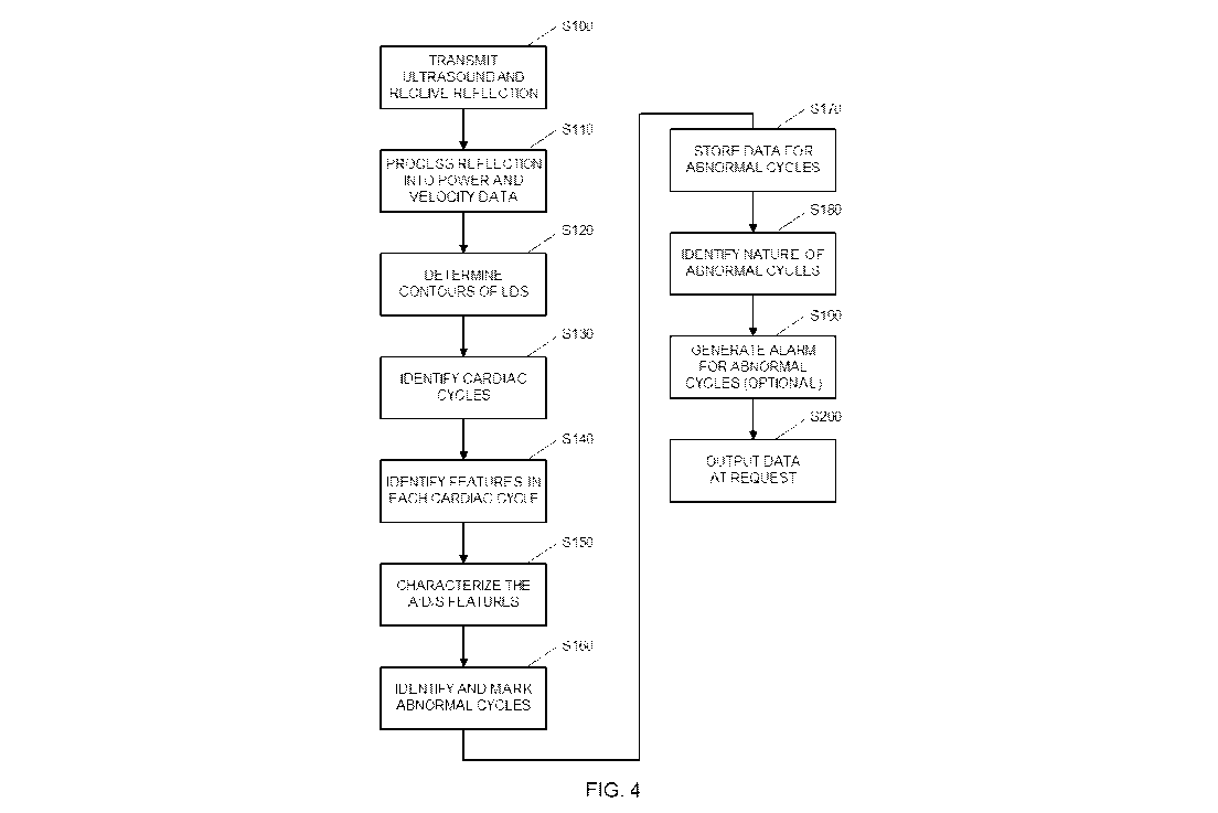
[0060] FIG. 4 is a schematic representation of the basic data handling
procedure that
is implemented by the processor 15 (shown in FIGS. 2A and 2B), and details of
the various
steps depicted in FIG. 4 are described below.
[0061] In step S100, ultrasound energy is transmitted into the patient,
and the
reflected ultrasound energy is received, in a conventional manner. In step
S110, Doppler
shifts in the received reflections are detected and processed into power and
velocity data in a
conventional manner, similar to the processing for conventional Doppler
Sonograms. Note
that because the Doppler returns from different positions on the patient's
chest are similar,
the placement of the transducer in an exact spot on the patient's chest in not
necessary.
[0062] Conventional Doppler systems collect power and velocity data from
many
different depths or gates (e.g., 16 gates). But because the returns from
different depths within
the patient's lungs are roughly similar, D-Holter systems do not have to
collect the Doppler
data from multiple gates. Instead, the data from a single gate can be used for
all subsequent
processing described herein. This results in a significant decrease in the
amount of data that
must be processed. Optionally, the optimal gate or gates can be determined by
analyzing the
CA 02970753 2017-06-13
WO 2016/113687 PCT/1B2016/050148
sonograms obtained from a few depths. Subsequently to this determination only
the selected
gate data will be stored.
[0063] In step S120, the contours (i.e., envelope) of the LDS power and
velocity data
is determined using any conventional envelope-detecting algorithm. The top
panel of FIG. 5
is an example of LDS power and velocity data 50 for a series of four
heartbeats. And the
trace 52 in the middle panel of FIG. 5 shows the contour (i.e., the envelope)
of that LDS data.
(Note once again that displays depicted in FIG. 5 are not generated by the D-
Holter system.
But they are included to explain what is happening in the various processing
steps.)
[0064] In step S130, the cardiac cycles are identified. An assumption is
made that
when the D-Holter is connected to the patient and activated, the heart rate is
usually operating
in steady state and the LDS are usually stable and repetitive. If this is not
the case (e.g., when
an arrhythmia is actively occurring), a regular ECG would suffice to make the
diagnosis. The
benefits of D-Holter are larger when the arrhythmias are intermittent,
especially when those
arrhythmias occur at a very low frequency of incidence.
[0065] An adaptive approach is preferably used in order to keep up with
any temporal
changes during the monitoring time, such as when the heart rate (HR) increases
(e.g., during
exertion) or decreases (when the exertion ends). The step of identifying
cardiac cycles is
therefore preferably updated periodically (e.g. every 30-60 seconds) and the
HR is re-
estimated.
[0066] The identification of cardiac cycles without relying on an ECG
signal is
preferably based on estimating the heart rate (HR) using a Matched Filtering
(MF) technique
that involves one or more templates of LDS data that correspond to a normal
cardiac cycle.
16
CA 02970753 2017-06-13
WO 2016/113687 PCT/1B2016/050148
[0067] In some preferred embodiments that rely on MF, a pair of templates
is used,
with one template of the pair being used for slower HRs, and the other
template of the pair
being used for faster HRs. It is advantageous to use different templates for
fast and slow
HRs, because the expected features of normal LDS varies as a function of the
HR. More
specifically, as the heart beats faster, the "A" and "D" features in the LDS
(as best seen in
FIG. 3A) move towards each other and eventually merge together into what
appears to be a
single "A" feature.
[0068] In these preferred embodiments, the step of identifying the
cardiac cycles
(i.e., S130) includes two major stages: estimating the HR and match filtering.
HR estimation
may be implemented, for example, by autocorrelation of the contour of the
spectrogram or
the raw data. The peaks of the autocorrelation are detected and the average
time difference
between the peaks is calculated. The reciprocal of the average time is the
estimated HR. The
variance of the time difference between the peaks is also defined as the EIR
estimated
variability. Once the EIR is determined, a template for match filtering is
selected based on
whether the EIR is greater than a threshold rate. A preferred threshold is an
EIR of 100, in
which case one MF template would be selected when the EIR is greater than 100
and the other
MF template would be selected when the EIR is less than 100. The envelope of
the LDS is
then match-filtered against the selected template. The purpose of this step is
detecting the
repeatability of a specific selected template. The output of the matched
filtering is a
continuous signal (or a digital representation thereof), the peak of which
represents the start
of each cardiac cycle.
[0069] The calculation is conducted in either one of the following two
cases: More
specifically, when the EIR is lower than the threshold, template A is used as
the MF kernel,
otherwise template B is used. In one preferred embodiment (referred to herein
as the Pattern
17
CA 02970753 2017-06-13
WO 2016/113687 PCT/1B2016/050148
I embodiment), the templates in the pair have the shapes depicted in FIGS. 6A
and 6B. In an
alternative preferred embodiment (referred to herein as the Pattern II
embodiment), the
templates in the pair have the shapes depicted in the FIGS. 7A and 7B.
[0070] In either scenario, the template is flipped and convoluted with
the LDS
spectrogram contour or the LDS raw data to calculate the matched filter
signal. The peaks of
this signal are determined. A single cardiac cycle (i) is represented by a
time frame that
extends from [detected peak (i) time] and ends in [detected peak (i) +
estimated cardiac cycle
duration (1/HR)] time.
[0071] Alternative approaches for identifying the cardiac cycles may also
be used.
For example, the contour data that was determined in step 120 may be analyzed
to determine
the highest velocity that appears in the contour over a given time (e.g., 2
seconds), and the
time at which that highest velocity was measured is deemed to be the start of
a cardiac cycle.
Because the LDS repeats in a periodic manner the vast majority of the time,
the next point in
time at which that same velocity appears (with a small tolerance of e.g., 5%)
is deemed to be
the start of the next cardiac cycle.
[0072] After identification of the cardiac cycles in step S130,
processing proceeds to
step S140, which is an optional step. In step S140, the various features of
each cardiac cycle
are identified. In the embodiment that uses Pattern I, the features are
identified in two
different ways, depending on the HR. More specifically, when the HR is lower
than the HR
threshold (discussed above); the "S" signal is defined as the signal in the
first third of the
cardiac cycle, the "D" signal is defined as the signal in the second third of
the cardiac cycle,
and the "A" signal is defined as the signal in the last third of the cardiac
cycle. When the HR
is more than the HR threshold; the "S" signal is defined as the signal in the
first half of the
cardiac cycle, the "A" is defined as the signal in the second half of the
cardiac cycle, and the
18
CA 02970753 2017-06-13
WO 2016/113687 PCT/1B2016/050148
"D" signal is defined as Null. FIGS. 8A and 8B depict these definitions for
the Pattern I
embodiment.
[0073] In the alternative embodiment that uses Pattern II, the features
are also
identified in two different ways, depending on the HR. When the HR is lower
than the HR
threshold; the "A" signal is defined as the signal in the first third of the
cardiac cycle, the "S"
signal is defined as the signal in the second third of the cardiac cycle, and
the "D" signal is
defined as the signal in the last third of the cardiac cycle. When the HR is
more than the HR
threshold; the "A" signal is defined as the signal in the first half of the
cardiac cycle, the "S"
is defined as the signal in the second half of the cardiac cycle, and the "D"
signal is defined
as Null. FIGS. 9A and 9B depict these definitions for the Pattern II
embodiment.
[0074] After identification of the cardiac cycles in step S140,
processing proceeds to
step S150, which is also an optional step. In step S150, characterizations of
the A, D, and S
features (which were identified in step S140) in are calculated from the LDS.
Examples of
these characterizations include power integrals, durations, average
velocities, peak velocities,
slopes, etc.
[0075] In step S160, any cycle that is abnormal is identified and marked.
One
example of an algorithm that may be used to determine which cycles are
abnormal is to
define normal cycles as one of the patterns used above (template A or template
B), depending
on the HR. All other patterns are defined as "Abnormal" cycles. Optionally, a
support-
vector-machine (SVM) based classifier may be used to implement this step. In
this situation,
the SVM is preferably trained offline to differentiate between the two
classes; Normal and
Abnormal cycles, using its features. The product of the learning (training)
stage is a
mathematical model which is used online to differentiate (classify) between
these classes,
preferably using a matched filter.
19
CA 02970753 2017-06-13
WO 2016/113687 PCT/1B2016/050148
[0076] In alternative embodiments, the decision to classify a cycle as
abnormal may
be based on a set of rules. Examples of rules that may be used to classify a
cycle as abnormal
include: (a) cycles in which the measured HR differs from an adaptive
estimation of HR that
is based on the HR of the previous few cycles by an amount that is larger than
a threshold
(e.g. 20%); (b) If the adaptive HR estimation switches from using pattern A to
B, or vice
versa; (c) If the estimated HR exceeds an upper threshold (e.g. 120 BPM) or
falls below a
lower threshold (e.g., 40 BPM); (d) if the features identified in step S140 do
not match an
expected set of features for a given HR (e.g., if an expected feature is
missing, or if an
unexpected extra feature is present; or (e) if a characterization of a feature
calculated in step
S150 has an unexpected value (e.g., if the duration of a feature exceeds an
expected value by
a threshold percentage). Cycles that do not meet one of the rules for an
"abnormal" cycle are
classified as normal.
[0077] In step S170, data for any cycle that has been identified in step
S160 as being
abnormal is stored in the memory 16 (shown in FIG. 2A and 2B). A time stamp
that
identifies the time of the abnormal cycle is preferably stored together with
the data for the
abnormal cycle. In some embodiments, only the power and velocity data for the
abnormal
cycle is stored. In these embodiments, there is no need to determine the
nature of the
abnormality in real time in the D-Holter device that is being worn by the
patient. Instead, the
nature of the abnormality can be determined by an external device at a later
time. This may
be accomplished at the end of the testing period, for example, by outputting
the power and
velocity data and associated time stamps for all abnormal cycles to the
external device, so
that the external device can analyze the data (and/or display the data so that
a human operator
can determine the nature of the abnormality).
CA 02970753 2017-06-13
WO 2016/113687 PCT/1B2016/050148
[0078] In those embodiment that perform the steps of identifying features
in the
cardiac cycle (step S140, discussed above), the storing step S170 preferably
includes storing
data for each abnormal cycle indicating which features were identified in step
S140. In those
embodiment that perform the steps of characterizing features in the cardiac
cycle (step S150,
discussed above), the storing step S170 preferably includes storing the
characterizations for
the features were characterized in step S150. In these embodiments, the power
and velocity
data for the abnormal cycle may also be stored in memory.
[0079] Notably, there is no need to store any data for any of the normal
cycles. This
dramatically reduces the memory that must be include in system, because the
vast majority of
cycles will be normal cycles. This is especially important when the power and
velocity data
itself is stored in memory, because that data is relatively large.
[0080] In step S180, which is an optional step, the nature of the
abnormal cycle is
identified. Examples of abnormal cycles include atrial extra systoles,
ventricular extra
systoles, atrial fibrillation (AF), and atrial flutter (AFT), and expected
feature patterns for
normal heartbeats and the four abnormal patterns mentioned above are shown in
FIGS. 10A-
10E, respectively. For example, as compared to the expected normal set of
features which is
shown in FIG. 10A, the "A" feature is missing at the end of the cardiac cycle
in AF (FIG.
10D), and a large number of extra "A" features are present in AFT (FIG. 10E).
Optionally,
within the set of "abnormal" cycles classified previously, the SVM may be used
with a
different models to identify which of the various abnormalities or arrhythmias
is present.
Any deviation from the normal expected patterns is recognized.
[0081] FIGS. 11A and 11B represent one example of performance measures
obtained
by an SVM classifier for recognizing AF. Sensitivity, Specificity and Accuracy
are used as
performance measures. More specifically, FIG. 11A represents the performance
obtained
21
CA 02970753 2017-06-13
WO 2016/113687 PCT/1B2016/050148
while learning and training using a validation set (using a set that included
2/3 of a set of 325
cardiac cycles known to represent AF, and 325 cardiac cycles of non-AF).
Assuming that the
SVM is trained properly, the validation performance will be a good estimate
for the future
performance of the SVM on unseen sets of new data.
[0082] FIG. 11B represents the performance obtained while using the SVM
with the
pre-trained model from the validation set on the remaining 1/3 of the set of
325 cardiac cycles
known to represent AF, plus the 325 cardiac cycles of non-AF. Both plots
(FIGS. 11A and
11B) show similar behavior, indicating that the learnt model is general enough
to correctly
classify previously unseen new data.
[0083] The testing depicted in FIGS. 11A and 11B was achieved as follows:
The
sonograms of five AF subjects and eight non-AF subjects were recorded and
sampled at 3
kHz, for a duration of 325 cardiac cycles for each subject. An algorithm that
calculates the
power integral in 80 msec windows that precede the start of S feature was
activated on the
data. SVM was used classify AF vs. non-AF cycles. As seen in FIG. 11, three
consecutive
cycles are identified with 90% accuracy / sensitivity / specificity within the
string of normal
cycles. These results establish that D-Holter can advantageously diagnose AF
with a very
high degree of certainty, even when the fibrillation episode is extremely
short (e.g., only 2-4
cycles embedded in a large number of normal cycles).
[0084] Similar performance can be expected in patients with atrial
flutter (AFT). In
these cases (see FIG. 10D), the excitatory electric signals are regular but
very rapid such that
the atria contract in synchrony but at a very high pace (as high as 400
contractions/min).
Under these conditions the cardiac conducting system cannot cope with the high
rate and
responds in ventricular contraction of much lower pace. Note that in this
case, the electric
activity that would be reflected in an ECG would be hard to diagnose in noisy
recordings and
22
CA 02970753 2017-06-13
WO 2016/113687 PCT/1B2016/050148
short episodes. In contrast, the LDS recordings for patients with AFT show a
chain or
multiple pronounced signals (labeled A in FIG. 10D) that dominate the tracing.
The flutter
signals that represent the synchronous atrial contraction are very distinct
and easily
recognizable. The D-Holter system is therefore superior to conventional ECG-
based Holter
systems for diagnosing AFT as well.
[0085] Returning now to FIG. 4, processing continues is step S190, which
is also an
optional step. In step 5190, an alarm or another indicator is used to notify
the patient or
medical personnel that an abnormal cycle has been detected. The alarm may
include audible
and/or visual alerts. Optionally, after a predetermined number of abnormal
cycles (e.g., 5-10)
have been detected, the patient may be notified that enough data has been
collected, and the
data collection process can be ended early. The notification may be
accomplished using
include audible and/or visual alerts. This will allow the patient to avoid
wearing the D-Holter
device longer than necessary, to minimize discomfort to the patient and cost.
[0086] After enough data has been collected (e.g., after 48 hours have
elapsed) or
after the predetermined number of abnormal cycles are detected, data
collection stops, and
the collected data is output in step S200. Returning to FIGS. 2A and 2B, this
may be
accomplished by having the processor 15 read the data that was stored in
memory in step
S170 to an external or remote computer via any conventional interface, such as
a wired
interface that uses connector 10 and/or a wireless interfaces (not shown).
[0087] An important advantage of D-Holter relates to detecting the
conditions of AF
and AFT. AF is a highly prevalent condition in people above 65. It is the
result of
desynchronized electric activity and as a result desynchronized contraction of
different areas
in the atria. The uncoordinated contractions render the atrial contraction
ineffective and thus
reduce the cardiac performance. Furthermore, AF may result in the formation
and
23
CA 02970753 2017-06-13
WO 2016/113687 PCT/1B2016/050148
dissemination of blood thrombi that may pose a serious medical problem such as
pulmonary
embolism.
[0088] The normal electric activity associated with atrial contraction,
the P wave of
the ECG, is small and sometimes hard to detect. In AF a minute irregular
oscillation replaces
the P wave. This abnormal electric activity is often very difficult to detect,
especially in noisy
recordings, and when the AF is interrupted by long intervals between
fibrillatory episodes. In
such cases the conventional ECG based Holter recording time needs to be very
long in order
to be sufficient for detection. However, the conventional ECG based Holter
wearing duration
usually does not extended beyond 24 ¨ 48 hours in view of the described
inconvenience to
the patient, in which case the AF condition may not be detected. This problem
is overcome
by using the D-Holter for two reasons: First, it is much more convenient to
use as it requires
only one electrode rather than the multi-electrode and complex wiring that are
required by the
conventional ECG based Holter monitors; and second, the AF condition is easier
to detect
based on the more obvious abnormality in the LDS (as opposed to the more
subtle
abnormality in the P wave of the ECG signals).
[0089] Another advantage of D-Holter over the conventional ECG based
Holter
systems is due to the fact that the D-Holter records the mechanical activity
of the heart rather
that the electric activity associated with the heart. The D-Holter signals
therefore provided a
clearer indication of each cardiac cycle, and its main components, from which
cardiac
rhythm, pulse intervals, etc. can be determined.
[0090] Another advantage of D-Holter over the conventional ECG based
Holter is
that LDS obtained from different positions on the chest wall have very similar
characteristics.
Therefore, in contrast to conventional ECG based Holter, relatively small
transducer
24
CA 02970753 2017-06-13
WO 2016/113687 PCT/1B2016/050148
movements with respect to the chest will not result in significant recording
changes or
movement artifacts in D-Holter systems.
[0091] Yet another advantage of D-Holter over the conventional ECG based
Holter is
that D-Holter measurements are much less sensitive to noise generated by
electric equipment
and by EMG generated by the chest muscles. FIG. 12 provides an example of how
the
readings obtained from both an LDS-based system and a conventional ECG-based
system can
change in the presence of patient movement. Note how the LDS (the upper trace
62) remains
relatively constant even though the patient is moving, while the ECG (the
lower trace 64)
drops out between t=147 and t=153 when the patient is moving.
[0092] Note that the embodiments described above are used to diagnose
various
cardiac abnormalities without relying on conventional ECG measurements.
However, in
alternative embodiments, the processing of the LDS described above may be
combined with a
conventional ECG-based system to obtain two different modalities of
information
simultaneously. Such embodiments may be useful to detect mechano-electric
dissociation.
[0093] While the present invention has been disclosed with reference to
certain
embodiments, numerous modifications, alterations, and changes to the described
embodiments are possible without departing from the sphere and scope of the
present
invention, as defined in the appended claims. Accordingly, it is intended that
the present
invention not be limited to the described embodiments, but that it has the
full scope defined
by the language of the following claims, and equivalents thereof