Note: Descriptions are shown in the official language in which they were submitted.
= 1
MULTICORE OPTICAL FIBER FOR MULTIPOINT DISTRIBUTED SENSING AND
PROBING
TECHNICAL FIELD
[0001] The technical field generally relates to optical fibers, and more
particularly to optical
fibers for use in multipoint quasi-distributed sensing and probing
applications.
BACKGROUND
[0002] Quasi-distributed fiber-optic sensors and probes enabling multipoint
light delivery
to and/or light collection from a region of interest have found applications
in various fields.
Examples of fields include medicine, optogenetics, biological and chemical
sensing,
environmental and structural monitoring, oil and gas industry, military, and
transportation.
These sensors and probes can provide various advantages including immunity to
electromagnetic interference, electrical passivity, small size and light
weight, resistance to
harsh environments, and possibility of multiplexed operation. However,
existing quasi-
distributed fiber-optic sensors and probes also possess limitations in terms
of sensitivity
and spatial resolution, especially for applications in space-confined and
other restricted
environments in which compact multipoint sensing and probing is required or
desired.
Challenges therefore remain in the development of optical fibers for use in
quasi-
distributed sensing and probing applications.
SUMMARY
[0003] The present description generally relates to techniques using a
multicore optical
fiber for light delivery and collection via a linear array of lateral coupling
zones
longitudinally distributed parallel to the fiber axis and azimuthally aligned
with one another.
Each one of the lateral coupling zones enables light to be laterally coupled
to and/or from
a corresponding core of the multicore optical fiber.
[0004] In accordance with an aspect, there is provided a multicore optical
fiber having a
fiber axis, the multicore optical fiber including:
¨ a cladding;
CA 2971051 2017-02-16
= 2
¨ multiple cores disposed in the cladding, each one of the multiple cores
following a
helical trajectory about the fiber axis; and
¨ a set of lateral coupling zones longitudinally distributed and
azimuthally aligned
with respect to the fiber axis, each one of the lateral coupling zones forming
an
optical coupling path extending and enabling lateral coupling of light between
a
corresponding one of the multiple cores and an exterior of the multicore
optical
fiber.
[0006] In some implementations, at least one of the lateral coupling zones
includes a
cavity extending inwardly from an outer lateral surface of the multicore
optical fiber toward
a corresponding one of the multiple cores.
[0006] In some implementations, the cavity extends at least partly into the
corresponding
core and defines an optical interface therebetween.
[0007] In some implementations, the optical interface is oriented with respect
to the
corresponding core to enable the lateral coupling of light to be effected via
total internal
reflection inside the corresponding core at the optical interface.
[0008] In some implementations, the at least one of the lateral coupling zones
further
includes a light reflector disposed inside the cavity and along the optical
coupling path.
[0009] In some implementations, the light reflector includes a reflective
layer deposited on
a wall of the cavity.
[0010] In some implementations, the light reflector includes a reflective
microsphere.
[0011] In some implementations, the cavity is filled at least partly with a
material having a
refractive index different than a refractive index of the corresponding core.
[0012] In some implementations, the at least one of the lateral coupling zones
further
includes focusing optics arranged on the outer lateral surface of the
multicore optical fiber
and extending over and across an opening of the cavity.
CA 2971051 2017-02-16
= 3
[0013] In some implementations, the cavity is spaced outwardly from the
corresponding
core in a manner such that a lateral gap is formed therebetween, the lateral
gap enabling
evanescent wave coupling of light thereacross between the corresponding core
and the
exterior of the multicore fiber.
[0014] In some implementations, the cavity is formed by laser processing.
[0015] In some implementations, at least one of the lateral coupling zones
includes a light
deflector arranged in the corresponding core.
[0016] In some implementations, the light deflector includes a fiber Bragg
grating, the fiber
Bragg grating having a grating axis tilted with respect to a light-guiding
path of the
corresponding core.
[0017] In some implementations, in a cross-section transverse to the fiber
axis, the
multiple cores are arranged along a perimeter of a closed-shape figure
centered with
respect to the fiber axis.
[0018] In some implementations, at least one of the lateral coupling zones is
configured
to couple light from the corresponding one of the multiple cores to the
exterior of the
multicore optical fiber.
[0019] In some implementations, at least one of the lateral coupling zones is
configured
to couple light from the exterior of the multicore optical fiber to the
corresponding one of
the multiple cores.
[0020] In some implementations, at least one of the lateral coupling zones is
configured
to couple light both out of and into the corresponding one of the multiple
cores.
[0021] In some implementations, the helical trajectory of each core has a
spatial repetition
period ranging from 5 millimeters (mm) to 50 centimeters (cm).
[0022] In some implementations, adjacent ones of the lateral coupling zones
are spaced-
apart by a distance ranging from 100 micrometers (pm) to 10 cm.
CA 2971051 2017-02-16
= 4
[0023] In some implementations, the lateral coupling zones are uniformly
spaced-apart.
[0024] In some implementations, the multiple cores include between 2 and 50
cores.
[0026] In some implementations, the helical trajectories followed by the
multiple cores
result from a permanent spin imparted to the multicore optical fiber.
[0026] In some implementations, each one of the multiple cores follows the
helical
trajectory along an entire length thereof.
[0027] In some implementations, each one of the multiple cores follows the
helical
trajectory along a partial length thereof.
[0028] In some implementations, the multicore optical fiber further includes a
centered
core coaxially aligned with and following a straight trajectory along the
fiber axis.
[0029] In accordance with another aspect, there is provided an optical probing
system for
at least one of light delivery to and light collection from a probed region.
The optical probing
system includes a multicore optical fiber having a fiber axis and including a
cladding,
multiple cores disposed in the cladding and extending helically about the
fiber axis, and a
set of lateral coupling zones longitudinally distributed and azimuthally
aligned with respect
to the fiber axis. Each one of the lateral coupling zones forms an optical
coupling path
enabling at least one of:
¨ lateral coupling of guided light out of a corresponding one of the multiple
cores for
delivery to the probed region; and
¨ collection of incoming light from the probed region for lateral coupling
into the
corresponding one of the multiple cores.
[0030] In some implementations, the optical probing system further includes a
light
injection assembly configured to inject the guided light into the multiple
cores.
[0031] In some implementations, the optical probing system further includes a
light
detection assembly configured to receive the collected light from the multiple
cores.
CA 2971051 2017-02-16
= 5
[0032] In some implementations, the optical probing system further includes an
additional
set of lateral coupling zones and at least one of:
¨ a light injection assembly coupled to the additional set of lateral
coupling zones
and configured to inject the guided light into the multiple cores; an
¨ a light detection assembly coupled to the additional set of lateral
coupling zones
and configured to receive the collected incoming light from the multiple
cores.
[0033] Other features and advantages of the present description will become
more
apparent upon reading of the following non-restrictive description of specific
embodiments
thereof, given by way of example only with reference to the accompanying
drawings.
BRIEF DESCRIPTION OF THE DRAWINGS
[0034] Fig. 1 is a schematic perspective view of a multicore optical fiber, in
accordance
with an exemplary embodiment.
[0035] Fig. 2 is another schematic perspective view of the multicore optical
fiber of Fig. 1,
wherein the cladding is shown as being transparent to better illustrate the
helical
trajectories followed by the multiple cores around the fiber axis.
[0036] Fig. 3 is a longitudinal cross-sectional view of the multicore optical
fiber of Fig. 1,
taken along section line 3, depicting the longitudinal distribution of lateral
coupling zones
along the length of the fiber.
[00371 Figs. 4A to 4D are transverse cross-sectional views of the multicore
optical fiber of
Fig. 1, taken along section lines 4A to 4D. Each one of Figs. 4A to 4D depicts
a different
one of the longitudinally distributed lateral coupling zones.
[0038] Fig. 5 is a schematic perspective view of a multicore optical fiber, in
accordance
with another exemplary embodiment, in which each one of the multiple cores
follows a
helical trajectory only along a partial length thereof. The cladding is shown
as being
transparent to better illustrate the helical trajectories followed by the
multiple cores around
the fiber axis.
CA 2971051 2017-02-16
= 6
[0039] Fig. 6 is a schematic perspective view of a multicore optical fiber, in
accordance
with another exemplary embodiment, in which the multicore optical fiber
includes multiple
off-centered cores extending helically about a centered core coaxially aligned
with the fiber
axis. The cladding is shown as being transparent to better illustrate the
helical trajectories
followed by the multiple cores around the fiber axis.
[0040] Fig. 7 is a schematic plan view of a multicore optical fiber, in
accordance with
another exemplary embodiment, illustrating the helical trajectories followed
by the cores
and the arrangement of the lateral coupling zones.
[0041] Fig. 8 is a schematic longitudinal cross-sectional view of a lateral
coupling zone of
a multicore optical fiber, in accordance with a first variant, in which the
lateral coupling
zone includes a cavity and a curved light reflector deposited inside the
cavity.
[0042] Fig. 9 is a schematic longitudinal cross-sectional view of a lateral
coupling zone of
a multicore optical fiber, in accordance with a second variant, in which the
lateral coupling
zone includes a cavity and a plane light reflector deposited on the cavity.
[0043] Fig. 10 is a schematic longitudinal cross-sectional view of a lateral
coupling zone
of a multicore optical fiber, in accordance with a third variant, in which the
lateral coupling
zone includes a cavity forming an optical interface with the core and enabling
coupling of
light by total internal reflection of light upon the core side of the optical
interface.
[0044] Fig. 11 is a schematic longitudinal cross-sectional view of a lateral
coupling zone
of a multicore optical fiber, in accordance with a fourth variant, in which
the lateral coupling
zone includes a cavity and a light reflector embodied by a reflective
microsphere located
inside the cavity.
[0046] Fig. 12 is a schematic longitudinal cross-sectional view of a lateral
coupling zone
of a multicore optical fiber, in accordance with a fifth variant, in which the
lateral coupling
zone includes a light deflector disposed in the core.
CA 2971051 2017-02-16
= 7
[0046] Fig. 13 is a schematic longitudinal cross-sectional view of a lateral
coupling zone
of a multicore optical fiber, in accordance with a sixth variant, in which
lateral coupling of
light is achieved by evanescent wave coupling.
[0047] Fig. 14 is a schematic representation of an optical probing system for
light delivery
and light collection, in accordance with an embodiment. Fig. 14A is an
enlargement of
portion 14A of Fig. 14.
[0048] Fig. 15 is a schematic representation of an optical probing system for
light delivery
and light collection, in accordance with another embodiment, including two
longitudinally
spaced-apart sets of lateral coupling zones.
[0049] Fig. 16 is a schematic representation of an optical probing system for
light delivery
and light collection, in accordance with another embodiment, in which each
lateral
coupling zone is used either for light delivery or light collection.
[0050] Fig. 17 is a schematic representation of an optical probing system for
light delivery,
in accordance with another embodiment, in which all the lateral coupling zones
are used
only for light delivery.
[0051] Fig. 18 is a schematic representation of an optical probing system for
light
collection, in accordance with another embodiment, in which all the lateral
coupling zones
are used only for light collection.
[0052] Fig. 19 is a schematic representation of an optical probing system for
light delivery,
in accordance with another embodiment, including a set of lateral coupling
zones for light
delivery to a probed region and an additional set of lateral coupling zones
coupled to a
light injection assembly.
[0053] Fig. 20 is a schematic representation of an optical probing system for
light
collection, in accordance with another embodiment, including a set of lateral
coupling
zones for light collection from a probed region and an additional set of
lateral coupling
zones coupled to a light detection assembly.
CA 2971051 2017-02-16
= 8
DETAILED DESCRIPTION
[0064] In the following description, similar features in the drawings have
been given similar
reference numerals and, to not unduly encumber the figures, some elements may
not be
indicated on some figures if they were already identified in one or more
preceding figures.
It should also be understood herein that the elements of the drawings are not
necessarily
depicted to scale, since emphasis is placed upon clearly illustrating the
elements and
structures of the present embodiments.
[0056] The present description generally relates to a multicore optical fiber.
The multicore
optical fiber includes multiple cores disposed in a cladding and having at
least a portion
thereof following a helical trajectory along the length of the fiber. The
multicore optical fiber
also includes a set of longitudinally distributed and azimuthally aligned
lateral coupling
zones for enabling lateral optical coupling between the multiple cores and the
outside of
the fiber. The present description also generally relates to an optical fiber-
based probing
system including such a multicore optical fiber for at least one of light
delivery to and light
collection from a probed region.
[0066] The present techniques can be used in a variety of multipoint quasi-
distributed
fiber-based sensing and probing applications where it is desirable to provide
lateral optical
coupling. The present techniques can be implemented in various types of fiber-
based
systems intended for use in fields such as, for example and without
limitation,
biophotonics, chemical sensing, telecommunications (e.g., for coupling with an
array of
injection laser diodes), and spectroscopy. Non-limiting examples of possible
applications
include: delivery of optically encoded stimulation signals for medical
applications (e.g.,
optical cochlear neuron stimulation) with millimetric or sub-miliimetric
spatial resolution;
depth-dependent analysis of tissue; or depth-dependent spatial addressing at
high spatial
or high spectral resolution in optogenetics or fiber ertdoscopy, with or
without recollection
of the optical signal emitted from the sample under test; light delivery to
and/or light
collection from a series of densely packed photonic integrated circuits; and
light injection
into a multicore fiber from a linear array of fibers or directly from a linear
laser diode array
or a set of planar micro-chips for sensing or telecommunication applications.
[0057] In the present description, the terms "quasi-distributed" is intended
to refer to the
fact that the multicore optical fiber disclosed herein enables lateral
coupling of light
CA 2971051 2017-02-16
= 9
between the multiple cores and the environment at discrete, spaced-apart
locations that
are longitudinally distributed along the fiber axis.
[0058] In the present description, the term "optical probe" and variants
thereof are
intended to refer to any optical system or device which can deliver optical
energy to a
region of interest and/or collect optical energy from the region of interest.
More particularly,
the term "optical probe" and variants thereof is meant to encompass optical
systems and
devices used solely for light delivery, optical systems and devices used
solely for light
collection, and optical systems and devices used for both light delivery and
light collection.
[0069] In the present description, the terms "light" and "optical" are
intended to refer to
radiation in any appropriate region of the electromagnetic spectrum. The terms
"light" and
"optical" are therefore not limited to visible light, but can include, for
example, the infrared
wavelength range. For example, in some embodiments, the signals guided by the
multicore optical fiber can have wavelengths ranging from about 400 nm to
about
1800 nm. Of course, other wavelength ranges may be considered in other
embodiments.
[0060] In the present description, the terms "longitudinal" and "axial", and
variants thereof,
are intended to refer to a direction that is parallel or near parallel to the
length of the
multicore optical fiber. Meanwhile, the terms "transverse", "lateral" and
"radial", and
variants thereof, are intended to refer to a direction that lies in a plane
perpendicular or
substantially perpendicular to the length of the multicore optical fiber and
to the longitudinal
and axial directions as just defined.
Multicore optical fiber
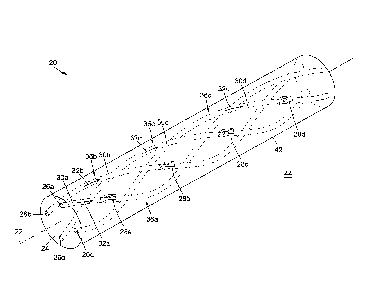
[0061] Referring to Figs. Ito 3 and 4A to 4D, there is illustrated an
exemplary embodiment
of a multicore optical fiber 20 having a fiber axis 22. For brevity, the
expression "multicore
optical fiber" may, in some instances, be shortened to "multicore fiber",
"optical fiber" or
simply "fiber". It is also noted that the term "fiber axis" may be used
interchangeably with
the terms "longitudinal axis" and "longitudinal fiber axis".
[0062] The multicore fiber 20 generally includes a cladding 24, multiple off-
centered
cores 26a to 26d embedded in the cladding 24, and a set of lateral coupling
zones 28a to
28d distributed at spaced-apart intervals parallel to the fiber axis 22. Each
lateral coupling
CA 2971051 2017-02-16
40 10
zone 28a to 28d enables in-coupling of light to and/or out-coupling of light
from a
corresponding one of the cores 26a to 26d. More detail regarding the
structure,
configuration and operation of these and other possible components of the
multicore
optical fiber 20 will be provided below.
[0063] For ease of representation, the multicore optical fiber 20 illustrated
in Figs. 1 to 3
and 4A to 40 includes only four cores 26a to 26d disposed in a single-layer
cladding 24
having a circular outer contour. However, depending on the application, the
cladding 24
may have a circular or non-circular geometry, and may have either a single-
layer structure
or a multilayer structure (e.g., double-clad and triple-clad structures).
Also, in other
embodiments, the fiber 20 can include two, three or more than four cores. In
some non-
limiting embodiments, the multicore fiber 20 can include between 2 and 50
cores, for
example between 6 and 18 cores.
[0064] In the embodiment of Figs. I to 3 and 4A to 40, the cores 26a to 26d
form light-
guiding paths 30a to 30d along which respective optical signals 32a to 32d are
guided. To
this end, each of the cores 26a to 26d is made of a material having a
refractive index
higher than the refractive index of the cladding material. Depending on the
application, the
multicore fiber 20 can have various cladding and core compositions and exhibit
different
refractive index profiles (e.g., graded-index profile or a step-index
profile). For example, in
some embodiments, the cladding 24 can be made of pure silica and the cores 26a
to 26d
can be made of silica containing one or more index-changing dopants (e.g.,
rare-earth
dopant materials such as erbium, ytterbium and thulium in the case of active
fibers, and
Ge02, P205, A1203, and F in the case of passive fibers). In other embodiments,
other
suitable materials can be used for the cladding and the cores (e.g., plastic,
sapphire, and
composite glasses).
[0065] Each one of the cores 26a to 26d has a circular cross-section. However,
a non-
circular cross-section (e.g., elliptical) is possible in other embodiments. In
some non-
limiting embodiments, the cores 26a to 26d can have a diameter ranging from
about 5 pm
to about 30 pm, although other core sizes can be used in other embodiments.
The core
size can depend on various factors, for example the number of cores and the
cross-
sectional overall size of the multicore fiber 20. Each of the cores 26a to 26d
can be either
single mode or multimode. It is noted that multimode cores can generally
provide better
CA 2971051 2017-02-16
= 11
lateral coupling efficiency, which can be advantageous in scenarios where the
optical
power of the laterally coupled light is of importance.
[0066] The arrangement of the cores 26a to 26d over the cross-section of the
fiber 20 can
assume various symmetrical or non-symmetrical configurations. For example, in
some
implementations, the cores 26a to 26d can be arranged, uniformly or not, along
a
perimeter of a closed-shape figure 34, as shown in Fig. 4A. The closed-shape
figure 34
may or may not be centered with respect to the fiber axis 22. In some
implementations,
the closed-shape figure 34 may be a circle or another curved shape. In other
implementations, the closed-shape figure 34 may be a polygon, regular or
irregular, in
which case the cores 26a to 26d can be located at vertices of the polygon. For
example,
in the embodiment of Figs. 1 to 3 and 4A to 4D, the four cores 26a to 26d are
located at
the corners of a square centered on the fiber axis 22. In yet other
implementations, the
locations of the cores 26a to 26d can correspond to lattice points of an array
or to arbitrary
locations that do not conform to a specific pattern. It will be understood
that the spacing
between the cores 26a to 26d is generally sufficiently large to avoid
excessive mutual
inter-core coupling.
[0067] It is noted that depending on the application, the composition, cross-
sectional
shape and size, refractive index profile, number of guided modes, passive or
active
operation mode, polarization-maintaining properties and other core properties
may be the
same or differ among the different cores.
[0068] Referring still to Figs. 1 to 3 and 4A to 4D, the cores 26a to 26d
follow respective
helical trajectories 36a to 36d about the fiber axis 22. As shown more
specifically in the
transverse cross-sectional views of Figs. 4A to 4D, as each core 26a to 26d
travels along
its respective helical trajectory 36a to 36d, the azimuthal angle it makes
with respect to
the fiber axis 22 gradually changes. Depending on the application, each core
26a to 26d
can extend along its helical trajectory 36a to 36d along the entire length
thereof, as
illustrated in the embodiment of Figs. 1 to 3 and 4A to 4D, or along a partial
length thereof,
as illustrated in the embodiment of Fig. 5.
CA 2971051 2017-02-16
= 12
[0069] The terms "helix", "helical", "helicoidal" and variants thereof refer
to a three-
dimensional figure that involves both a rotation around and a translation
along a helix axis,
which generally coincides with the fiber axis.
[0070] More particularly, the term "helical trajectory" is intended to
describe the general
configuration in which each one of the off-centered cores is wrapped or coiled
around the
fiber axis. It is noted that the terms "helix", "helical", "helicoidal" and
variants thereof are
not intended to be construed by their strictest geometrical definition and are
meant to
encompass both true helices (i.e., circular helices with a constant radius of
curvature) and
helix-like structures having a non-constant radius of curvature. Depending on
the
application, the helix can have a spatial repetition period and a helix angle
which may be
constant or vary along the helix axis.
[0071] Various techniques can be used to impart a helical configuration to the
off-centered
cores of the multicore fiber disclosed herein. In some implementations, the
multicore fiber
can have a permanent spin imparted thereto along the fiber axis. Such
specialty optical
fibers can be referred to as "spun fibers". It will be understood that by
imparting a spin
along a multicore fiber having multiple off-centered cores, a spun multicore
fiber is
obtained in which the off-centered cores rotate in a helical fashion about the
fiber axis.
[0072] In the present description, the terms "spin", "spun" and other
derivatives thereof
are intended to refer to a torsional deformation which is impressed on the
multicore fiber
while the fiber material is in a viscous and substantially unstressed state,
and which is
preserved as a permanent structural modification after the fiber has cooled
down. In this
context, the term "permanent" is intended to refer to a deformation which is
essentially
non-reversible under normal operating conditions and for the intended lifetime
of the
multicore optical fiber.
[0073] In some implementations, a spun multicore fiber can be obtained during
the
drawing process, using either a preform spinning technique, in which the
preform is
rotated, or a fiber spinning technique, in which the fiber is rotated. In
other
implementations, a spun multicore fiber can be obtained by post-drawing
processing.
Such processing can involve the following steps: performing a conventional
drawing
process to obtain an "unspun" multicore fiber, that is, a multicore fiber
produced without
CA 2971051 2017-02-16
= 13
spin; locally heating the unspun multicore fiber to bring at least a portion
thereof to a soft
and viscous state; applying a torque to the locally heated portion of the
unspun fiber such
that a spin is imparted to the locally heated portion and preserved as a
frozen-in structural
modification upon cooling. While the application of this technique is often
restricted to a
limited segment of a fiber, it can provide increased flexibility in terms of
engineering the
imparted spin properties.
[0074] In general, a spun optical fiber can be characterized by a spin
function or profile.
In the present description, the term "spin function" is intended to refer to
the rate (e.g., in
units of degrees per unit length or turns per unit length) and direction
(i.e., left-handed or
right-handed) of the spin imparted to the fiber as a function of position
along the fiber. The
spin function may be of any kind, although spin functions with a constant rate
are often
favored. Moreover, the spin impressed on the fiber may have a constant
handedness (i.e.,
a unidirectional spin function that is either everywhere left-handed or
everywhere right-
handed) along the fiber or may alternate, periodically or not, between a left-
handed and a
right-handed helicity.
[0076] The spin function can also be characterized by a spin pitch, or spatial
repetition
period. The spin pitch represents the length of fiber needed to complete a 360
rotation
about the fiber axis. For example, in some implementations, the multicore
optical fiber
disclosed herein can have a spin pitch that ranges from about one centimeter
to a few
tens of centimeters or more (e.g., from about 5 mm to about 50 cm in a non-
limiting
embodiment). Of course, other spin pitch values can be used in other
embodiments.
Depending on the application, the spin pitch may be constant or vary,
periodically or not,
as a function of the position along the fiber axis, and different cores may
have the same
or different spin pitch values. More detail regarding the spin pitch and how
its value can
be used to control the longitudinal spacing between the lateral coupling zones
of the
multicore fiber will be described further below.
[0076] It should be noted that the terms "spin" and "twist" are employed in
the art to
describe two distinct types of rotation or torsion that can be impressed on a
fiber. This
distinction will be adopted in the present description. As defined above, the
term "spin"
refers to a rotation applied to the fiber in a way that produces a
substantially permanent
deformation after cooling. In contrast, the term "twist" refers to an elastic
rotation applied
CA 2971051 2017-02-16
= 14
to a post-drawn fiber in a way such that the fiber will return to its original
state after
removing the torsional torque. Depending on the application, the multicore
fiber disclosed
herein may be either spun or twisted. In some implementations, spun fibers can
be favored
compared to twisted fibers due to their mechanical stability, resistance to
long-term
fatigue, and manufacturing flexibility that can allow short and/or
longitudinally varying
spatial repetition periods.
[0077] Turning briefly to Fig. 6, it should be noted that if the multicore
optical fiber 20 also
includes a centered core 38, in addition to the multiple off-centered cores
26a to 26d, the
centered core 38 would not follow a helical path, but would remain generally
straight and
coaxially aligned with the fiber axis 22.
[0078] Returning to the embodiment of Figs. 1 to 3 and 4A to 4D, the multicore
optical
fiber 20 includes a set of lateral coupling zones 28a to 28d. The lateral
coupling zones 28a
to 28d are longitudinally spaced-apart from and azimuthally aligned with one
another
relative to the fiber axis 22. Each one of the lateral coupling zones 28a to
28d forms an
optical coupling path or optical channel 40a to 40d that extends between a
corresponding
one of the cores 26a to 26d and an outer lateral surface 42 of the multicore
fiber 20, and
that enables coupling of light between the corresponding core 26a to 26d and
the
exterior 44 of the fiber 20.
[0079] In the present description, the term "lateral coupling zone" generally
refers to a
zone in the multicore fiber in which optical energy can travel or be coupled
between one
of the cores and a location outside of the multicore fiber. For brevity, the
term "lateral
coupling zone" may, in some instances, be shortened to "coupling zone".
Depending on
the application, the lateral coupling zones can provide both unidirectional
and bidirectional
optical coupling, and be configured to transmit all or a portion of the light
received therein,
in either direction. In some implementations, the coupling efficiency can be
spectrally
dependent. Also, depending on the application, the lateral coupling zones can
enable
optical coupling to be effected either by direct optical coupling (see, e.g.,
Figs. 8 to 12) or
by evanescent wave coupling (see, e.g., Fig. 13).
[0080] In the present description, the term "lateral" when referring to the
lateral coupling
zones is intended to refer to the fact that light coupling between the
corresponding core
CA 2971051 2017-02-16
= 15
and the exterior of the fiber is effected through the outer lateral surface of
the multicore
fiber, rather than, for example, through a fiber endface. It is noted that the
term "lateral
coupling" may, in some instances, be used interchangeably with the terms
"radial coupling"
and "side coupling".
[0081] When referring to the spatial arrangement of the set of lateral
coupling zones, the
term "longitudinally distributed" is intended to refer herein to the fact that
the set of lateral
coupling zones is arranged in a manner such that the individual coupling zones
are
disposed, formed or otherwise provided at discrete, spaced-apart locations
along the
length of the fiber. By way of example, the longitudinal cross-sectional view
of Fig. 3 shows
the spaced-apart distribution of the lateral coupling zones 28a to 28d along
the fiber
axis 22. It will be understood that such longitudinally distributed coupling
zones 28a to 28d
can provide multipoint quasi-distributed sensing and probing along the fiber
axis 22.
[0082] When referring to the spatial arrangement of the set of lateral
coupling zones, the
term "azimuthally aligned" is intended to refer herein to the fact that all
the lateral coupling
zones in the set are located at the same azimuthal position or angle in the
multicore fiber,
the azimuthal position or angle being defined relative to the fiber axis. The
term
"azimuthally aligned" is also intended to refer to the fact that all the
lateral coupling zones
in the set are provided in a common azimuthal plane or within a common
azimuthal angular
range with respect to the fiber axis. By way of example, referring to the
transverse cross-
sectional views of Figs. 4A to 4D, it is seen that the four lateral coupling
zones 28a to 28d
are all formed at the same azimuthal position (at 1:30 o'clock position in the
figures)
around the fiber axis 22.
[0083] It is noted that a set of longitudinally distributed lateral coupling
zones provided at
the same azimuth in the multicore fiber can be referred to as a "linear array
of longitudinally
distributed lateral coupling zones". It is also noted that the terms
"azimuthal" and
"azimuthally aligned" may, in some instances, be used interchangeably with the
terms
"circumferential" and "circumferentially aligned", respectively.
[0084] In some implementations, using a set of longitudinally distributed and
azimuthally
aligned lateral coupling zones for enabling multipoint quasi-distributed light
injection to
and/or light collection from a multicore optical fiber with a helical core
arrangement can be
CA 2971051 2017-02-16
= 16
advantageous for applications in space-confined and other restricted
environments where
multipoint sensing and probing over an azimuthally narrow range of angles is
required or
desired. The fact the lateral coupling zones are all provided on the same
optical fiber can
also be an advantage in terms of compactness and design simplicity in
spatially restricted
environments.
[0086] Referring to Figs. 4A to 4D, the optical coupling path 40a to 40d of
each lateral
coupling zone 28a to 28b is the path or channel along which lateral optical
coupling is
effected between the corresponding core 26a to 26d and the exterior 44 of the
fiber 20.
Each optical coupling path 40a to 40d has an inner end 46 and an outer end 48.
The inner
end 46 is located at a point along the helical trajectory followed by the core
26a to 26d,
while the outer end 48 is located at a point on the outer lateral surface 42
of the fiber 20.
It should be noted that the optical coupling path 40a to 40d of each lateral
coupling
zone 28a to 28d need not extend solely in a lateral direction with respect to
the fiber
axis 22, but may exhibit a slight longitudinal deviation or slope as it
extends between its
inner end 46 and its outer end 48.
[0086] Referring to Figs. 1 to 3 and 4A to 4D, in some implementations, one,
some, or all
of the lateral coupling zones 28a to 28d can enable bidirectional coupling of
light between
the cores 26a to 26d and the exterior 44 of the fiber 20. This or these
coupling zones 28a
to 28d allow both in-coupling and out-coupling of light to and from the cores
26a to 26d
via the set of discrete, longitudinally distributed lateral coupling zones 28a
to 28d. In such
implementations, the multicore optical fiber 20 can be used in applications
requiring
multipoint quasi-distributed light delivery and collection.
[0087] In some implementations, one, some, or all of the lateral coupling
zones 28a to 28d
can enable light to be transmitted from the cores 26a to 26d to the exterior
44 of the
fiber 20. This or these coupling zones 28a to 28d allow light to escape or be
out-coupled
from the cores 26a to 26d. In such implementations, the multicore optical
fiber 20 can be
used in multipoint quasi-distributed light delivery applications, in which
guided light 32 is
coupled out the multiple cores 26a to 26d via the set of discrete,
longitudinally distributed
lateral coupling zones 28a to 28d. For example, in Fig. 17, all the cores 26a
to 26d are
used for unidirectional light delivery.
CA 2971051 2017-02-16
= 17
[0088] In some implementations, one, some, or all of the lateral coupling
zones 28a to 28d
can enable light to be received from the exterior 44 to the cores 26a to 26d
of the fiber 20.
This or these coupling zones 28a to 28d allow light to be injected in or be in-
coupled to
the cores 26a to 26d. In such implementations, the multicore optical fiber 20
can be used
in multipoint quasi-distributed light collection applications, in which
incoming light from a
region of interest is coupled into the multiple cores 26a to 26d via the set
of discrete,
longitudinally distributed lateral coupling zones 28a to 28d. For example, in
Fig. 18, all the
cores 26a to 26d are used for unidirectional light collection.
[0089] Therefore, depending on the application or use of the multicore optical
fiber, each
lateral coupling zone can therefore provide one of the following types of
optical coupling:
unidirectional coupling of light from the corresponding core to the exterior
of the fiber (i.e.,
unidirectional coupling for light delivery); unidirectional coupling of light
from the exterior
of the fiber to the corresponding core (i.e., unidirectional coupling for
light collection); and
coupling of light from the corresponding core to the exterior of the fiber,
and vice versa
(i.e., bidirectional coupling for simultaneous light delivery and collection).
Lateral coupling
zones with different configurations can be used to provide different types of
optical
coupling. By way of example, in some implementations, each coupling zone can
be
configured to couple light in a specific spectral range selected in accordance
with the
wavelength(s) of the light traveling in the corresponding core.
[0090] Returning to Figs. 1 to 3 and 4A to 4D, in some implementations, the
distance
between adjacent coupling zones 28a to 28d can range from a few hundreds of
micrometers to a few centimeters, and in some implementations from 1 mm to 10
mm.
Depending on the application, the lateral coupling zones 28a to 28d can be
uniformly
spaced-part, as in Figs. 1 to 3 and 4A to 4D, or nonuniformly spaced-apart.
[0091] Referring to Fig. 7, the minimum achievable distance Dzone between
adjacent
coupling zones 28a to 28d is generally related to the number Nõ,-, of
helically arranged
cores 26a to 26d and the spin pitch Psp,n of their helical trajectories 36a to
36d, as follows:
Pspin = Ncore X Dzone. As mentioned above, the multicore fiber 20 may include
between 2
and 50 cores, and the spin pitch Pspin can be as short as 5 mm. Therefore,
using for
example Ncore = 20 and Pspin = 5 mm, the distance Dzone between adjacent
coupling
zones 28a to 28d can be as small as 250 pm. Such small values can be
advantageous for
CA 2971051 2017-02-16
= 18
multipoint quasi-distributed sensing and probing applications where spatial
resolution is of
importance, especially considering that the lateral coupling zones are not
only
longitudinally distributed, but also azimuthally aligned. This azimuthal
alignment allows
light delivery and/collection to be confined within a narrow range of
azimuthal angles.
[0092] It will be understood that in the exemplary embodiments described so
far, the
lateral coupling zones are arranged in a "close-packed" configuration, in
which the
longitudinal distance between adjacent coupling zones is equal to the
longitudinal offset
between the helical trajectories of adjacent cores. Of course, in other
embodiments, the
lateral coupling zones can be arranged into more complex configurations in
terms of order
and mutual separations provided that they remain in a longitudinally
distributed and
azimuthally aligned arrangement with respect to the fiber axis.
[0093] It will also be understood that in the exemplary embodiments described
so far, only
a single set of longitudinally distributed and azimuthally aligned lateral
coupling zones was
considered, in which the number of coupling zones was equal to the number of
multiple
cores. However, in other variants the multicore fiber can include a plurality
of sets of
longitudinally distributed and azimuthally aligned lateral coupling zones. For
example, in
some embodiments, the different sets can be longitudinally spaced-apart from
one
another, but they may or may not be azimuthally aligned with one another. It
is noted that
depending on the application, the number of coupling zones in each set can be
less or
greater than the number of cores in the multicore fiber, provided that, in any
given set, the
coupling zones remain in a longitudinally distributed and azimuthally aligned
arrangement
with respect to the fiber axis.
[0094] It will therefore be understood that depending on the application or
use of the
multicore optical fiber, the lateral coupling zones can have a variety of
structures,
configurations, and operation principles, which may be the same or different
for each
lateral coupling zone. Several non-limiting examples of implementations for
the lateral
coupling zones will now be described with reference to Figs. 8 to 13.
[0095] It is noted that, unless explicitly stated otherwise, each of these
exemplary
implementations are reciprocal, which means that they enable light to be
coupled laterally
from the core to the exterior of the fiber as readily as they do from the
exterior to the core
CA 2971051 2017-02-16
4111 19
of the fiber. It is also noted that each of the exemplary implementations
illustrated in Figs. 8
to 13 will be described by considering a single lateral coupling zone 28
forming an optical
coupling path 40 that enables lateral coupling of light between a
corresponding core 26
and the exterior 44 of a multicore fiber 20. As mentioned above, the
corresponding core 26
is disposed in a cladding 24 and has a light-guiding path 30 that follows a
helical
trajectory 36 about the fiber axis 22. However, it will be understood that
each of these
examples can be used for one, some, or all of the lateral coupling zones of
the fiber. It is
further noted that other non-limiting examples of lateral coupling
arrangements that may
be suitable for implementing the lateral coupling zones disclosed herein are
described in
co-assigned U.S. Patent Nos. 7,209,605 and 7,883,535.
[0096] Referring to Fig. 8, there is shown a first exemplary implementation of
a lateral
coupling zone 28 of a multicore optical fiber 20. In this implementation, the
lateral coupling
zone 28 includes a cavity 50 formed by removing part of the cladding 24 and
the core 26.
The cavity 50 extends inwardly from the outer lateral surface 42 of the fiber
20 into the
cladding 24 and at least partly into the core 26. By way of example, in the
illustrated
embodiment, the cavity 50 extends through and beyond the core 26 to terminate
in the
cladding 24. The cavity 50 has a cavity opening 52 defined through the outer
lateral
surface 42 of the fiber 20 and a cavity wall 54 extending from the cavity
opening 52 and
defining a cavity interior 56 terminating in a closed bottom 58. The cavity 50
has a limited
extent both longitudinally (e.g., between about 50 pm and about 100 pm) and
azimuthally
(e.g., between about 50 pm and about 100 pm) over the outer lateral surface 42
of the
fiber 20. The size of the cavity 50 can be determined based on the application
requirements, for example in terms of spatial resolution and/or sensitivity.
The cavity
wall 54 has a portion thereof that defines an optical interface 60 between the
cavity
interior 56, on a cavity side 62 of the interface 60, and the core 26, on a
core side 64 of
the interface 60.
[0097] The cavity 50 can be formed by laser processing (e.g., laser ablation
and laser
cutting), chemical or physical etching, mechanical techniques (e.g., drilling,
cutting, and
milling), or any other appropriate micromachining technique. By way of
example, in some
implementations, the cavity 50 can be formed by laser ablation, such as
femtosecond or
CO2 laser ablation. As known in the art, laser ablation can be used to
precisely and
CA 2971051 2017-02-16
= 20
accurately form cavities having complex and/or irregular shapes, ranging in
size from
about a few tens of micrometers to about a few hundred of micrometers.
[0098] Depending on the application, the cavity 50 may be hollow or be filled
at least partly
with a filling material. Several techniques exist for inserting a filling
material inside a cavity
and they need not be discussed in detail herein. In some implementations,
inserting a
filling material inside the cavity can help mitigating Fresnel reflections at
the optical
interface 60 between the core 26 and the cavity interior 56.
[0099] It will be understood that depending on the application, the coupling
efficiency
provided by the lateral coupling zone 28 can be optimized by proper selection
of the size
and shape of the cavity 50 and, if any, of the optical property of the filling
material, notably
its refractive index relative to the refractive indices of the core 26 and the
cladding 24. For
example, in the embodiment of Fig. 8, the cavity 50 is hollow (i.e., filled
with air) and is
shaped as a half paraboloid. Of course, depending on the application, various
other
regular or irregular cavity shapes can be used. It is noted that the term
"cavity" can be
used interchangeably herein with terms such as "groove", "depression", "hole",
"recess",
"aperture", and the like.
[0100] In some implementations, the lateral coupling zone 28 can include a
light
reflector 66 located inside the cavity 50 along the optical coupling path 40.
In the present
description, the term "light reflector" refers to an optical element or a
combination of optical
elements which can reflect, at least partly, the light incident thereonto. In
some
implementations, the light reflector 66 can be a reflective layer deposited
over a portion of
the cavity wall 54. For example, the reflective layer can be embodied by a
metallic mirror
(e.g., a thin metallic layer or film) or a dielectric mirror (e.g., a stack of
dielectric thin films).
Depending on the application, the light reflector 66 can be plane or curved.
By way of
example, in the illustrated embodiment, the light reflector 66 is embodied by
a half
paraboloidal reflector, but other light reflector shapes can be used in other
embodiments.
[0101] Referring still to Fig. 8, the light reflector 66 can be disposed on
the cavity wall 54
such that the optical coupling path 40 formed by the lateral coupling zone 28
includes both
a reflection off the light reflector 66 on the cavity side 62 of the optical
interface 60 and a
transmission across the optical interface 60 between the core side 64 and the
cavity
CA 2971051 2017-02-16
11110 21
side 62. Depending on whether light is coupled out of or into the core 26, the
transmission
will precede or follow the reflection along the optical coupling path 40.
[0102] In the out-coupling direction, guided light 32 propagating in the core
26 toward the
cavity 50 will be transmitted across the optical interface 60 and into the
cavity 50. Inside
the cavity 50, the transmitted light 68 will impinge on and be reflected by
the light
reflector 66 toward the cavity opening 52 and out of the fiber 20 as outcoming
light 70.
Meanwhile, in the in-coupling direction, incoming light 72 passing through the
cavity
opening 52 will impinge on and be reflected by the light reflector 66 toward
the optical
interface 60. The reflected light 74 will then be transmitted across the
optical interface 60
and into the core 26, inside which it will propagate as collected light 76
away from the
cavity 50.
[0103] Referring now to Fig. 9, another exemplary implementation of a lateral
coupling
zone 28 is shown. The features of this implementation are generally similar to
like features
described for the implementation of Fig. 8, and they will not be repeated in
detail below
except for highlighting differences. The lateral coupling zone 28 of Fig. 9
differs from that
of Fig. 8 in that the cavity 50 is shaped as a triangular prism rather than as
a half
paraboloid, such that the light reflector 66 is a plane reflector rather than
a curved one.
Also, the cavity 50 in Fig. 9 is filled with a filling material 78.
[0104] The lateral coupling zone 28 in Fig. 9 includes focusing optics 80
extending across
the opening 52 of the cavity 50 to increase the coupling efficiency of light
in and out of the
fiber 20. For example, in the illustrated embodiment, the focusing optics 80
is embodied
by a piano-convex lens having a flat side 82a facing the cavity 50 and a
curved side 82b
facing the exterior 44 of the fiber 20. In such a configuration, the provision
of a piano-
convex lens can allow the out-coupled light 70 to exit the cavity 50 as a
focusing or
converging beam of light. It is noted that while Fig. 9 only shows light being
coupled from
the core 26 to the exterior 44 of the fiber 20, this implementation could also
enable light
coupling from the exterior 44 of the fiber 20 to the core 26.
[0105] Turning now to Fig. 10, another exemplary implementation of a lateral
coupling
zone 28 is shown. The implementation shown in Fig. 10 differs from the
implementations
shown in Figs. 8 and 9 in the principle according to which light is laterally
coupled by the
CA 2971051 2017-02-16
= 22
cavity 50 between the core 26 and the exterior 44 of the fiber 20. In contrast
to the
implementations of Figs. 8 and 9, the cavity 50 in the implementation of Fig.
10 does not
include a light reflector and is also not traversed by the optical coupling
path 40 between
the core 26 and the exterior 44 of the fiber 20. Instead, the cavity 50 in
Fig. 10 is shaped
such that the optical interface 60 between the core 26 and the cavity interior
56 where light
is coupled from and/or to the core 26 makes an angle 0 with respect to the
light-guiding
path 30 of the core 26 that provides total internal reflection of light from
the core side 64
of the interface 60.
[0106] As such, the optical coupling path 40 formed by the lateral coupling
zone 28
includes a total internal reflection of light on the core side 64 of the
optical interface 60,
but no transmission across the interface 60. More particularly, this means
that in the out-
coupling direction, guided light 32 propagating in the core 26 toward the
cavity 50 will
undergo total internal reflection at the optical interface 60 and be coupled
out of the
fiber 20 as outcoming or delivered light 70. Similarly, in the in-coupling
direction, incoming
light 72 from the exterior 44 of the fiber 20 will traverse the cladding 24,
undergo total
internal reflection at the optical interface 60, and be coupled into the core
for propagation
therealong as collected light 76. In some variants, a filling material (not
shown) may be
inserted inside the cavity 50, if required to achieve total internal
reflection. It is noted that
forming the cavity 50 with a shape such as that shown in Fig. 10 is readily
possible using
conventional micromachining techniques. It is also noted that the
implementation of
Fig. 10 can be advantageous in terms of manufacturing cost, since no light
reflector needs
to be deposited inside the cavity.
[0107] Referring to Fig. 11, in another embodiment, the lateral coupling zone
28 can
include a cavity 50 such as described above and a light reflector embodied by
a reflective
microsphere 86 located inside the cavity 50. In this embodiment, lateral
optical coupling
between the core 26 and the exterior 44 of the fiber 20 is effected by
reflection of light on
the reflective microsphere 86, as illustrated in Fig. 11. The reflective
microsphere 86 may
be glued or otherwise held in place inside the cavity 50. In other variants,
the reflective
microsphere 86 may be replaced with a similar reflective structure, such as,
for example,
a bead or a micro-prism.
CA 2971051 2017-02-16
= 23
[0108] Each one of the embodiments of Figs. 8 to 11 includes lateral coupling
zones
embodied by longitudinally distributed and azimuthally aligned cavities formed
by
removing material from the outer lateral surface of the multicore fiber 20.
The spacing
between such cavities can be of the order of a few hundreds of micrometers
using existing
spinning and micromachining techniques, which may be advantageous in
applications
where high spatial resolution is desired or required. It is noted that such
high spatial
resolution may not be readily achievable using other implementations of
lateral optical
coupling zones disclosed herein, such as lateral coupling zones based on
tilted or slanted
fiber Bragg gratings (see, e.g., the embodiment described below and
illustrated in Fig. 12),
for which a minimum grating length may be required to yield acceptable
coupling
efficiency. Moreover, in contrast to most implementations based on fiber Bragg
gratings,
implementations using lateral coupling zones based on cavities such as those
shown in
Figs. 8 to 11 need not work on a principle of resonance, which can allow a
more stable
and robust operation.
[0109] Referring to Fig. 12, in another embodiment, the lateral coupling zone
28 can
include a light deflector 88 disposed in the core 26 and enabling lateral
coupling of light
between the core 26 and the exterior 44 of the fiber 20. In the present
description, the term
"light deflector" refers to an optical element or a combination of optical
elements which
can deflect, at least partly, the optical path of light incident thereonto.
[0110] In the out-coupling configuration, the light deflector 88 is oriented
such that guided
light 32 traveling in the core 26 and hitting the light deflector 88 will be
deflected generally
laterally outwardly along a path that defines the optical coupling path 40 of
the lateral
coupling zone 28. As illustrated in Fig. 12, the optical coupling path 40
extends between
an inner end 46 located on the light deflector 88 and an outer end 48 located
on the outer
lateral surface 42 of the fiber 20. Meanwhile, in the in-coupling
configuration, the light
deflector 88 is oriented such that external light 72 entering generally
laterally into the
fiber 20 at the outer end 48 of the optical coupling path 40 will be deflected
into the core 26
for propagation therealong as collected light 76.
[0111] The light deflector 88 can be embodied by a reflecting, a refracting or
a diffracting
optical element, or a combination thereof. Non-limiting examples of light
deflectors include
dielectric reflectors (e.g., Bragg reflectors), metallic reflectors (e.g.,
plane and curved
CA 2971051 2017-02-16
= 24
mirrors), diffraction gratings (e.g., fiber Bragg gratings and embedded
photonic crystal
structures), and filters (e.g., interference filters). By way of example, in
the embodiment of
Fig. 12, the light deflector 88 is embodied by a tilted fiber Bragg grating
(FBG) whose
grating axis 90 is tilted with respect to the light-guiding path 30, for
example at a tilt angle
of 450 or another appropriate tilt angle. The fiber Bragg grating can for
example be
inscribed in the core 26 by conventional laser processing techniques.
[0112] In some implementations, the light deflector 88 may be a wavelength-
selective light
reflector configured to enable lateral coupling only for light in a selected
range of
wavelengths. However, in other implementations, the light deflector 88 may not
be
spectrally selective and may provide lateral coupling of light over a broad
spectral range.
It will be understood that in some implementations using a fiber Bragg
grating, lateral
optical coupling may be facilitated if the core is single mode. This is
because the operation
of fiber Bragg gratings is based on additive coherent addition of local
reflections from a
locally periodic variation of the refractive index. This positive interference
is wavelength-
and mode-dependent (through their effective refractive index). In a multimode
core, the
coherent addition of all contributions cannot be mode-independent, which
implies an
overall reduced reflection.
[0113] Referring to Fig. 13, in yet another embodiment, the lateral coupling
zone 28 can
enable lateral coupling between the core 26 to the exterior 44 of the fiber 20
by
evanescent-wave coupling. In this regard, it should be noted that while the
embodiment of
Fig. 13 illustrates a scenario where evanescent wave coupling is used to
provide lateral
out-coupling of light, lateral in-coupling of light by evanescent wave
interaction may also
be possible in some scenarios.
[0114] As known in the art, the evanescent field of light guided in the core
of an optical
fiber remains usually confined inside the cladding. This means that in order
for the
evanescent field to "leak out" of the fiber and interact with the surrounding
medium (e.g. a
sample or a region of interest), the evanescent field must be made to extend
at least partly
out of the fiber. Referring to Fig. 13, in some implementations, this can be
achieved by
locally etching, tapering, polishing or otherwise machining a region of the
cladding 24 to
reduce the thickness of the cladding 24 and bring the outer lateral surface 42
of the
CA 2971051 2017-02-16
= 25
fiber 20 closer to the core 26. The machined region of the cladding 24 defines
the lateral
coupling zone 28 of the fiber 20.
[0116] Referring still to Fig. 13, in some implementations, the lateral
coupling zone 28
includes a cavity 50 extending inwardly from the outer lateral surface 42 of
the fiber 20
and terminating into the cladding 24 at a depth such that a lateral gap 92
remains between
a bottom 94 of the cavity 50 and the core 26. This lateral gap 92 can be
adjusted to fulfill
the conditions for enabling lateral evanescent wave coupling between the core
26 and the
exterior 44 of the fiber 20. That is, the evanescent field of the guided light
32 traveling in
the core 26 is coupled out of the core 26 as delivered light 70. By way of
example, in some
non-limiting implementations, the lateral gap can have a thickness ranging
from about
1 pm to about 5 pm. It will be understood that to provide multipoint quasi-
distributed light
delivery to a region or sample of interest, the cavity 50 defining the lateral
coupling zone 28
generally has a limited extent both longitudinally (e.g., between about 100 pm
and a few
millimeters) and azimuthally (e.g., between about 50 pm and about 100 pm) on
the outer
lateral surface 42 of the fiber 20.
Optical probing system
[0116] Referring now to Figs. 14 and 14A, in accordance with another aspect,
there may
be provided an optical probing system 100 for at least one of light delivery
to and light
collection from a probed region 200.
[0117] Depending on the application, the probed region 200 refers to any
region of interest
which the optical probing system disclosed herein can sense, detect, monitor,
interrogate,
excite, stimulate or otherwise probe by delivering light thereto and/or
collecting light
therefrom. The term "probed region" is to be interpreted broadly to encompass
any object,
structure, substance, material, person or other living organism, environment,
medium or
region of space to which light can transmitted and/or from which light can be
received.
[0118] The optical probing system 100 first includes a multicore optical fiber
20 according
to any one of the embodiments and variants described above or equivalents
thereof. The
multicore optical fiber 20 includes a cladding 24, multiple cores 26a to 26d
disposed in the
cladding 24 and extending helically about the fiber axis 22, and a set of
lateral coupling
zones 28a to 28d longitudinally distributed and azimuthally aligned with
respect to the fiber
CA 2971051 2017-02-16
= 26
axis 22. Each lateral coupling zone 28a to 28d forms an optical coupling path
that enables
either or both of: (1) coupling of guided light 32 out of a corresponding core
26a to 26d for
delivery, as delivered light 70, to the probed region 200; and/or (ii)
collection of incoming
light 72 from the probed region for coupling, as collected light 76, into the
corresponding
core 26a to 26d.
[0119] Referring still to Figs. 14 and 14A, in some implementations, the
optical probing
system 100 can also include a light injection assembly 102. The light
injection
assembly 102 is configured to inject light 96 into the multiple cores 26a to
26d for
propagation therealong as the guided light 32. The guided light 32 is guided
along the
cores 26a to 26d until it reaches the set of lateral coupling zones 28a to
28d, at which
point the guided light 32 is coupled out of the cores 26a to 26d via the
lateral coupling
zones 28a to 28d and delivered to the probed region 200 as probing light 70.
[0120] In the embodiment of Figs. 14 and 14A, the light injection assembly 102
is
configured to inject light into the multiple cores 26a to 26d via an input
endface 98a of the
multicore optical fiber 20, Since various optical coupling techniques are
known in the art
for injecting light through an endface of a multicore optical fiber, a
detailed discussion of
their structure and operation will not be provided herein. By way of example,
some of these
techniques can involve endface coupling through free-space optics, optical
fibers, or
multicore connectors. It is noted that because some implementations of the
present
techniques do not require the cores to be single mode, such implementations
can facilitate
the injection of light into the cores of the multicore fibers.
26 [0121] In the embodiment of Figs. 14 and 14A, the light injection
assembly 102 first
includes a light source module 104 configured to generate input light 96
having multiple
spectral components A1 to A4, each spectral component Ai to A4 having a
wavelength
selected from a plurality of different wavelengths. By way of example, four
such spectral
components Al to A4 are used in the embodiment of Figs. 14 and 14A. The light
source
module 104 can be embodied by any appropriate device or combination of devices
able
to generate input light for the intended probing application. In some
implementations, the
light source module 104 can include one or more laser sources configured to
generate the
input light 96 having the multiple spectral components Al to A4. In other
variants, different
types of light sources can be used besides lasers sources, including, without
limitation,
CA 2971051 2017-02-16
= 27
= light-emitting diodes (LEDs) and other broadband light sources. The
choice of the light
source module can be dictated by several factors depending on the application
in which
the optical probing system is intended to be used.
[0122] Referring still to Figs. 14 and 14A, the light injection assembly 102
also includes
injection optics 106 disposed in a path of the input light 96 generated by the
light source
module 104. The injection optics 106 can be embodied by any appropriate device
or
combination of devices able to split spectrally and spatially the input light
96 into its
spectral components Al to A4 along distinct paths, and to direct each one of
the split
spectral components A1 to A4 into a different corresponding one of the
multiple cores 26a
to 26d for coupling thereto via the input endface 98a of the multicore optical
fiber 20. By
way of example, in the embodiment of Figs. 14 and 14A, the injection optics
106 includes
a diffraction grating 108 to split the input light 96 into its spectral
components Al to A4, and
focusing optics 110 (e.g., lenses) to focus each one of the split spectral
components Al to
A4 into the corresponding cores 26a to 26d. Of course, various other
arrangements for the
injection optics can be used in other implementations.
[0123] It should be noted that while Figs. 14 and 14A provide a multiple-
wavelength
implementation, in which each one of the cores 26a to 26d is injected with
light having a
specific wavelength, single-wavelength implementations, in which each one of
the
cores 26a to 26d is injected with light having the same wavelength, are also
possible. In
such scenarios, it will be understood that the injection optics splits the
input light 96 only
spatially, and not spectrally. For instance, the splitting of the input light
96 can be such
that each one of the cores 26a to 26d receives the same amount of optical
power.
[0124] Referring still to Figs. 14 and 14A, the multiple spectral components
Al to A4 are
injected into the multiple cores 26a to 26d as multiple guided signals that
together form
the guided light 32. The multiple guided signals propagate along the multiple
cores 26a to
26d toward the set of lateral coupling zones 28a to 28d. Once they reach the
set of lateral
coupling zones 28a to 28d, the guided signals are successively coupled out of
the
cores 26a to 26d and delivered to the probed region 200 as a set of
longitudinally
distributed and azimuthally aligned probing signals 70a to 70d. The set of
probing
signals 70a to 70d forms the probing light 70 referred to above.
CA 2971051 2017-02-16
= 28
[0125] In the illustrated embodiment, the probing signals 70a to 70d interact
with the
probed region 200 and induce an optical response from the probed region 200.
For
example, each probing signal 70a to 70d may excite one of a plurality of
probed sites (not
shown) provided in the probed region 200. Without limitation, this optical
response can
include light emanating from the probed region 200 due to transmission,
reflection,
refraction, diffraction, scattering, interference, emission, absorption,
and/or nonlinear
optical phenomena. The incoming light 72 from the probed region 200 can be
collected
into the multicore fiber 20 as incoming light signals 72a to 72d via the set
of lateral coupling
zones 28a to 28d. That is, the lateral coupling zones 28a to 28d enable
coupling of the
incoming light signals 72a to 72d into the corresponding core 26a to 26d for
propagation
therealong as collected light signals 76a to 76d. The collected light signals
together form
the collected light 76.
[0126] Referring still to Figs. 14 and 14A, in some implementations, the
optical probing
system 100 can further include a light detection assembly 112 configured to
receive the
collected light 76 from the multiple cores 26a to 26d after coupling therein
via, and
propagation therealong away from, the set of lateral coupling zones 28a to
28d. In the
illustrated embodiment, the collected light 76 is emitted from the multiple
cores 26a to 26d
at the output endface 98b of the multicore optical fiber 20 which is the same
as the input
endface 98a. This is because the same lateral coupling zones 28a to 28d are
used in this
embodiment for both light delivery and light collection, with the result that
the light to be
delivered to and the light collected from the probed region 200 propagate in
opposite
directions between the lateral coupling zones and one of the fiber endface.
[0127] Turning briefly to Fig. 15, in another embodiment, the multicore fiber
20 can include
a first set of lateral coupling zones 28a' to 28d' and a second set of lateral
coupling
zones 28a" to 28d" provided downstream of the first set with respect to the
direction of
light propagation in the fiber 20. In this embodiment, the light injection
assembly 102 is
configured to inject light 96 into the cores 26a to 26d via the endface 98a of
the fiber 20.
The injected light propagates as guided light 32 along the cores 26a to 26d
until it reaches
the first set of lateral coupling zones 28a' to 28d'. There, the guided light
32 is coupled out
of the cores 26a to 26d and delivered as probing light 70 to the probed region
200.
Meanwhile, incoming light 72 from the probed region 200 is coupled into the
cores 26a to
26d via the second set of lateral coupling zones 28a" to 28d" and guided along
the
CA 2971051 2017-02-16
= 29
cores 26a to 26d toward the opposite endface 98b of the fiber 20. There, the
collected
light 76 is outputted from the fiber 20 and directed to the light detection
assembly 112.
[0128] Returning to Figs. 14 and 14A, the light detection assembly 112 can
include an
optical detector 114 and suitable detection optics 116. The optical detector
114 can be
embodied by any appropriate device or combination of devices able to detect
the light 76
collected from the probed region 200 and outputted from the multiple cores 26a
to 26d as
different collected light signals. The detection optics 116 can be embodied by
any optical
components arranged to provide an optical path for the collected light as it
travels from
the output endface 98b of the fiber 20 to the optical detector 114. The
detection optics 116
can include lenses, mirrors, filters, and any other suitable reflective,
refractive and/or
diffractive optical components.
[0129] The choice of the optical detector can be dictated by several factors
depending on
the nature of the application in which the optical probing system is used,
notably the types
of optical phenomenon that are to be detected and analyzed. In some
implementations,
the optical detector 114 can be embodied by various types of square law
detectors and
spectral detectors including, without limitation, a photodiode array, a
photomultiplier array,
a complementary metal-oxide-semiconductor (CMOS) array, a charge-coupled
device
(CCD) array, a charge injection device (CID) array, another type of pixelated
or non-
pixelated detector, a spectrometer, an optical spectrum analyzer, an optical
vector
analyzer, or another type of spectral measuring device. The signal(s) from the
optical
detector 114 output can be subsequently processed and analyzed to yield
information
about the probed region 200.
[0130] As mentioned above, in the illustrated embodiment, the same fiber
endface is used
for both injecting the guided light 32 into and outputting the collected light
76 from the
multiple cores 26a to 26d. In such scenarios, a light separator 118, may be
provided to
separate the collected light 76 outputted from the fiber 20 from the input
light 96 to be
injected in the fiber 20. Depending on the application, the light separator
118 can be
embodied by various optical components including, without limitation, an
optical circulator,
a directional coupler, a multi-channel optical add-drop multiplexer, or a
dichroic filter in
cases where the injection light and the collected light have different
wavelengths.
CA 2971051 2017-02-16
= 30
[01311 It is noted that in the embodiment of Figs. 14 and 14A, each one of the
lateral
coupling zones 28a to 28d is used for both light delivery and light
collection. Turning to
Fig. 16, in other embodiments, each one of the lateral coupling zones 28a to
28d may be
used only for either light delivery (i.e., coupling zones 28a and 28b in Fig.
16) or light
collection (i.e., coupling zones 28c and 28d in Fig. 16). In such scenarios,
the configuration
of the lateral coupling zones 28a and 28b used for light delivery can differ
from the
configuration of the lateral coupling zones 28c and 28d used for light
collection, for
example if the delivered light and the collected light have different
wavelengths.
[0132] In yet other variants, one or more coupling zones in the set may be
used for
unidirectional coupling (either in-coupling or out-coupling), while the
remainder of the set
may be used for bidirectional coupling.
[0133] Referring to Fig. 17, in another embodiment, the optical probing system
100 can
be used only for light delivery to a probed region 200. In this embodiment,
the optical
probing system 100 can include a multicore optical fiber 20 and a light
injection
assembly 102, but no light detection assembly. The light injection assembly
102 can be
configured to inject light 96 into the multiple cores 26a to 26d of the fiber
20 for
propagation therealong as guided light 32. The guided light 32 is guided along
the
cores 26a to 26d until it reaches the set of lateral coupling zones 28a to
28d, at which
point the guided light 32 is coupled out of the cores 26a to 26d via the
lateral coupling
zones 28a to 28d and delivered to the probed region 200 as probing signals 70a
to 70d
forming probing light 70. In such scenarios, the delivery of the probing light
70 to the
probed region 200 may or may not elicit an optical response from the probed
region 200,
but if it does, then any resulting light emanating from the probed region 200
will not be
collected by the lateral coupling zones 28a to 28d of the fiber 20.
[0134] Referring to Fig. 18, in a further embodiment, the optical probing
system 100 can
be used only for light collection from a probed region 200. In this
embodiment, the optical
probing system 100 can include a multicore optical fiber 20 and a light
detection
assembly 112, but no light injection assembly. Light 72 originating from the
probed
region 200 can be coupled into the fiber 20 as collected light 76 through the
set of lateral
coupling zones 28a to 28d. This collected light 76 can be guided along the
multiple
cores 26a to 26d toward the output endface 98b of the fiber 20. There, the
collected
CA 2971051 2017-02-16
= 31
light 76 escapes from the fiber 20 and is directed to the light detection
assembly 112. In
such scenarios, the light 72 originating from the probed region 200 may or may
not have
been induced by an applied optical excitation, but if it is, then this optical
excitation is not
applied to the probed region 200 via the lateral coupling zones 28a to 28d of
the fiber 20.
[0135] Referring to Fig. 19, in another embodiment, the optical probing system
100 can
include yet another set of lateral coupling zones 120a to 120d in addition to
a set of lateral
coupling zones 28a to 28d used for light delivery to the probed region 200.
The additional
set of lateral coupling zones 120a to 120d is coupled to the light injection
assembly 102
to enable individual injection of input light signals 96a to 96d into each one
of the multiple
cores 26a to 26d. To this end, the light injection assembly 102 can include a
linear array
of laser diodes 104a to 104d, each one of the laser diodes 104a to 104d
emitting a
respective one of the input light signals. The array of laser diodes 104a to
104d is arranged
with respect to the additional set of lateral coupling zones 120a to 120d such
that each
one of the laser diodes 104a to 104d directs its respective input light signal
96a to 96d into
the corresponding coupling zone 120a to 120d of the additional set for
coupling into and
propagation as guided light 32 along the corresponding one of the multiple
cores 26a to
26d of the fiber 20. In some variants, a coplanar array of parallel optical
fibers can be used
instead of a linear array of laser diodes to inject the input light signals
96a to 96d into the
additional set of lateral coupling zones 120a to 120d. The guided light 32 is
guided along
the cores 26a to 26d until it reaches the set of lateral coupling zones 28a to
28d, at which
point the guided light 32 is coupled out of the cores 26a to 26d via the
lateral coupling
zones 28a to 28d and delivered to the probed region 200 as probing signals 70a
to 70d.
[0136] Referring to Fig. 20, in another embodiment, the optical probing system
100 can
include a set of lateral coupling zones 122a to 122d in addition to a set of
lateral coupling
zones 28a to 28d used for light collection from the probed region 200. Light
signals 72a to
72d originating from the probed region 200 can be coupled into the fiber 20 as
collected
light signals 76a to 76d through the set of lateral coupling zones 28a to 28d.
The collected
light signals 76a to 76d are guided as collected light 76 along the multiple
cores 26a to
26d. The additional set of lateral coupling zones 122a to 122d is used to
couple the
collected light signals 76a to 76d individually out of each of the multiple
cores 26a to 26d.
The light detection assembly 112 can include a linear array of photodetectors
114a to
114d arranged with respect to the fiber 20 in such a way that each of the
CA 2971051 2017-02-16
= 32
photodetectors 114a to 114d receives and detects a respective one of the
collected light
signals 76a to 76d outputted from the additional lateral coupling zones 122a
to 122d.
[0137] Returning to the embodiment of the multicore optical fiber 20
illustrated in Figs. 1
to 3 and 4A to 40, it is noted that, for some applications, the lateral
coupling zones 28a to
28d of the fiber 20 may be used for light injection into the cores 26a to 26d
from a light
injection assembly and/or light extraction from the cores 26a to 26d for
detection by a light
detection assembly, but not for light delivery to and/or light collection from
a probed region.
[0138] It is also noted that in other applications, the multicore optical
fiber disclosed herein
can be used for one, some, or all of light delivery to a probed region, light
collection from
a probed region, light injection from a light injection assembly and light
extraction for
detection by a light detection assembly.
[0139] Of course, numerous modifications could be made to the embodiments
described
above without departing from the scope of the appended claims.
CA 2971051 2017-02-16