Note: Descriptions are shown in the official language in which they were submitted.
I
Title: Watercraft with Hydrofoil
Description of Invention
The present invention relates to a watercraft.
Many different types of watercraft are known, which adopt various means of
propulsion. The propulsion may be provided by an engine, sail or manually
provided by a user. Examples of such manual propulsion means are paddles
or oars. In a traditional rowing boat, a seated rower, facing away from the
direction of travel, pulls on one or two oars, which serves to pull the boat
through the water using a lever action. The oars/paddles provide thrust to
carry the watercraft through the water.
Other known watercraft are powered by the use of a single oar extending from
the stern of the boat (e.g. a gondola). The watercraft is propelled through
the
water by the oarsman paddling the oar from side to side.
Various manually propelled watercraft are known from CN101973384,
JPH11291984, FR2565549, DE2840411 and W02012021954.
The present invention seeks to provide an alternative watercraft.
Accordingly, the present invention provides a watercraft comprising:
a chassis;
a drive means;
a hydrofoil; and
Date Recue/Date Received 2022-04-05
2
a drive transfer arm, wherein the drive means is operatively connected
to a first end of the drive transfer arm, and the hydrofoil is pivotably
connected
to a second end of the drive transfer arm,
the watercraft configured such that operation of the drive means causes
the hydrofoil to oscillate, to provide thrust.
Preferably, the watercraft is configured such that operation of the drive
means
causes the hydrofoil to oscillate, to provide both thrust and vertical lift.
Preferably, the hydrofoil is pivotably connected to the second end of the
drive
transfer arm with an adjustable connection mechanism, wherein the distance
between the leading edge of the hydrofoil and the rotational axis of the
pivoting
connection point to the drive transfer arm is adjustable.
Preferably, the watercraft further comprises a control member, operable to
adjust the distance between the leading edge of the hydrofoil and the
rotational axis of the pivoting connection point to the drive transfer arm.
Preferably, the drive means are rotary drive means.
Preferably, the drive means are manually operated by the user of the
watercraft.
Preferably, the manual drive means include a crankset provided with pedals.
Preferably, the drive means further includes a drive wheel operatively
connected to the crankset, wherein the drive wheel is operatively connected to
the first end of the drive transfer arm.
Preferably, the watercraft further comprises a gear arrangement between the
drive wheel and the crankset.
Date Recue/Date Received 2022-04-05
3
Preferably, the watercraft is configured such that for each complete
revolution
of a pedal about the crankset, the hydrofoil completes two oscillation cycles.
Preferably, the drive means is a rotary drive means, and the watercraft
further
comprises a connecting rod,
wherein a first end of the connecting rod is pivotably connected to the
rotary drive wheel at a predetermined distance from the axis of rotation of
the
rotary drive wheel, and the second end of the connective rod is pivotably
connected to the first end of the drive transfer means,
wherein rotation of the rotary drive wheel causes the second end of the
drive arm to prescribe said arcuate path.
Preferably, the drive means comprises a motor.
Preferably, the hydrofoil is substantially pitch stable.
Preferably, the hydrofoil comprises at least one controllable flap.
Preferably, the drive transfer arm is pivotably secured to the chassis, such
that
the second end of the drive transfer arm prescribes an arcuate path in use.
Preferably, the watercraft further comprises a support arm rigidly connected
at
a first section to the drive transfer arm is pivotably connected at a second
section to the chassis, such that the drive transfer arm is rotatable about an
axis passing through the pivoting connection of the support arm to the
chassis.
Preferably, the watercraft further comprises a spring operatively connected
between the chassis and the first end of the drive arm.
Date Recue/Date Received 2022-04-05
4
Preferably, the rotation of the hydrofoil relative to the longitudinal axis of
the
drive transfer arm is limited to within a predetermined range.
Preferably, the hydrofoil is a self-stable reflexed hydrofoil.
Preferably, the hydrofoil has a non-uniform angle of incidence across its
span.
Preferably, the watercraft further comprises a seat for a user, mounted on the
chassis.
Preferably, the seat is arranged to allow the user to sit in a recumbent
position.
Preferably, the watercraft further comprises at least one auxiliary hydrofoil
attached to the chassis, for providing additional lift.
Preferably, the watercraft further comprises.
Preferably, the watercraft is configured such that the inclined plane swept by
the hydrofoil in use, on the downwards stroke, follows a path which is
substantially twice as steep as the lift-to-drag ratio of the watercraft when
gliding through a fluid.
Embodiments of the present invention will now be described, by way of non-
limiting examples only, with reference to the figures in which:
Figure 1 illustrates a watercraft according to an embodiment of the present
invention;
Figure 2 illustrates an enlarged partial cross-section of the connection
mechanism between the drive transfer arm and the hydrofoil of a watercraft
embodying the present invention;
Date Recue/Date Received 2022-04-05
5
Figure 3 illustrates an enlarged view of the crankset 10 of an embodiment of
the invention.
Figure 4 illustrates another watercraft embodying the present invention;
Figure 5 illustrates the hydrofoil of the watercraft in Figure 4; and
Figure 6 illustrates a cross-section of the hydrofoil of figure 5.
Figure 1 illustrates a watercraft 1 embodying the present invention. The
watercraft 1 comprises a chassis 2, drive means 3 and a hydrofoil 4. The
watercraft 1 further comprises a drive transfer arm 5. The drive means 3 is
operatively connected to a first end 5a of the drive transfer arm 5. The
hydrofoil 4 is pivotably connected to a second end 5b of the drive transfer
arm
5.
As will be described in further detail below, the watercraft 1 is preferably
configured such that the operation of the drive means 3 causes the hydrofoil 4
to vertically oscillate, to provide both thrust (propulsion) and vertical lift
to the
watercraft 1. In other embodiments, described later, the hydrofoil is only
adopted to provide propulsion. In all embodiments, the direction of the
propulsion is preferably substantially parallel to the surface of the water.
In the embodiment shown in figure 1, the drive means 3 comprises rotary drive
means. The drive means 3 are manually operated by a user 6 of the
watercraft 1. A seat 7 is connected to the chassis 2. Preferably, the
watercraft
1 is configured such that the user 6 can sit in the seat 7 in a recumbent
position. A recumbent seating position is preferred but not essential. In
other
embodiments, other seating positions may be adopted, including an upright
position.
Date Recue/Date Received 2022-04-05
6
As illustrated in figure 1, the drive means 3 comprises a crankset 10 provided
with pedals 11. Preferably, the crankset 10 comprises two crank arms 12,
each provided with a pedal 11 at a distal end thereof. Preferably, the
longitudinal axes of each crank arm 12 are parallel to one another, such that
the crank arms 12 are arranged 1800 with respect to one another. The pedals
11 are pivotably connected to the distal end of the crank arms 12 in a
conventional manner. The drive means 3 further preferably includes a drive
wheel 13 operatively connected to the crankset 10. Preferably, the drive
wheel 13 is operatively connected to the crankset 10 by means of a chain 14
or a belt etc. A gearing arrangement is preferably provided between the drive
wheel 13 and the crankset 10. The gearing arrangement may be provided by
configuring each of the drive wheel 13 and crankset 10 to have a different
diameter. Other gearing mechanisms are possible. In another embodiment,
there may be no chain/belt provided, and the crankset and drive wheel may be
operatively connected in other ways. For example, both the crankset and drive
wheel may be provided with teeth which directly mesh with one another, or
comprise part of a larger gear train.
In the embodiment shown, the drive wheel 13 is operatively connected to a
first end 5a of the drive transfer arm 5, as will be described in more detail
below.
In an another embodiment, rather than provide a separate crankset 10 and
drive wheel 13 with optional gearing therebetween, the drive means 3 may
comprise a drive wheel to which the pedals are directly attached, thus
providing a direct drive arrangement. In the embodiment shown, the use of a
chain/belt is used in part so as to transfer the rotary motion from the
crankset
10 to a rearward position, where the drive wheel 13 is located. In applicable
embodiments, a gearbox may be provided between the drive means and the
drive wheel 13.
Date Recue/Date Received 2022-04-05
7
A support arm 15 is rigidly connected at a first section, adjacent the first
end
5a, of the drive transfer arm 5. In the embodiment shown, there are two
support arms 15a, 15b. The support arm(s) is pivotably connected at a
second end to the chassis 2, such that the drive transfer arm 5 is rotatable
about an axis 16 passing through the pivoting connection of the support arm
to the chassis 2. In the embodiment shown, both support arms 15a, 15b
terminate at the same point as the axis 16 of rotatable connection to the
chassis. It is to be noted from figure 1 that the longitudinal axis of the
drive
10 transfer arms 5 does not pass through the axis 16 about which the drive
transfer arm 5 is rotatable. Accordingly, when the drive transfer arm 5 is
rotated about the axis 16, both the first 5a and second 5b ends at the drive
transfer arm 5 prescribe arcuate paths.
15 The watercraft 1 further comprises a connecting rod 20. A first end
20a of the
connecting rod 20 is pivotably connected to the rotary drive wheel 13 at a
predetermined distance from the axis of rotation 21 of the rotary drive wheel
13. The second end 20b of the connecting rod 20 is pivotably connected to
the first end 5a of the drive transfer arm 5. The connecting rod 20
effectively
transforms the rotary motion of the drive wheel 13 into a substantially linear
motion at the end 20b of the connecting rod 20. However, by virtue of the
drive transfer arm 5 being pivotably connected to the chassis 2 via support
arm IS, the end 20b of the connecting rod 20 is constrained to follow an
arcuate path, about the axis 16 of rotation. The connecting rod 20 therefore
converts rotational motion of the drive wheel 13 into an oscillating arcuate
motion.
As noted above, the watercraft 1 illustrated in figure 1 causes the second end
5b of the drive transfer arm 5 to describe an oscillating arcuate path, in a
vertical plane. Since the distance from the axis 16 to the distal end 5b of
the
drive transfer arm 5 is greater than the distance from the axis 16 to the
first
Date Recue/Date Received 2022-04-05
8
end 5a of the drive transfer arm 5, the arcuate path described by the second
end 5b is longer than the path prescribed by the first end 5a.
The motion of the second end 5b of the drive transfer arm 5 causes a
corresponding vertically oscillating "flapping" motion of the hydrofoil 4.
Preferably, the watercraft 1 is configured such that for each complete
revolution of a respective pedal 11 about the rotational axis of the crankset
10,
the hydrofoil 4 completes two oscillation cycles. A particular benefit of this
arrangement is that the hydrofoil 'flaps' downwards for every downwards
stroke of each of the user's respective legs. This may be achieved with a 2:1
gearing ratio between the crankset 10 and the drive wheel 13.
An enlarged, cross-sectional, view of the pivoting connection between the
drive transfer arm 5 and the hydrofoil 4 is illustrated in figure 2. In the
embodiment shown, an adjustable connection mechanism 25 is provided
between the drive transfer arm 5 and the hydrofoil 4. As is known, the
hydrofoil 4, as with any foil, has a dynamic centre, in this case a
hydrodynamic
centre, where the pitching moment coefficient for the foil does not vary with
the
lift coefficient (i.e. the angle of attack). The hydrodynamic centre of the
hydrofoil 4 is not illustrated in figure 2.
With reference to figure 2, the hydrofoil 4 is pivotably connected to the
second
end 5b of the drive transfer arm 5 about an axis of rotation 30. Preferably,
the
hydrofoil 4 is substantially pitch stable.
The connection mechanism 25 comprises a male member 26 provided at the
second end 5b of the drive transfer arm 5, which is received in a female part
27 provided in a part of the hydrofoil 4. At least a part of the surface of
the
male member 26 may be substantially cylindrical, which is received in a
corresponding cup surface of the female part 27. Furthermore, the connection
Date Recue/Date Received 2022-04-05
9
mechanism 25 comprises a spring 28 received in an aperture within the
hydrofoil 4. The spring 28 provides a biasing force on the male member 26 of
the connection mechanism 25, urging it towards the leading edge of the
hydrofoil 4. The connection mechanism 25 further comprises a control
member 29, in this embodiment a control wire, which passes through the
centre of the drive transfer arm 5 and is operatively connected to a control
lever (not shown), or equivalent, on the chassis 2, for use by the user 6. The
lower end of the control member 29 is received within the hydrofoil 4. As the
control member 29 is tensioned in use, the tension force opposes the biasing
force of the spring 28. As a result, the position of the male member 26 of the
connection mechanism 25, and thus the axis of rotation 30 is adjusted by
adjusting the control member 29. A benefit of this arrangement is that it
enables the user to alter the angle of attack of the hydrofoil 4, and
therefore
"tune" the behaviour of the hydrofoil 4 to the speed of travel. For example,
the
user 6 may decrease the angle of attack as the speed of the watercraft
increases, and increase the angle of attack as the speed of the watercraft
decreases.
Other methods of adjusting the position of the pivot point along the chord of
the hydrofoil are possible. An alternative pivoting connection is shown in
figures 4 to 6.
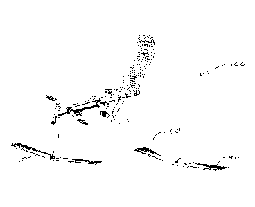
In the embodiment in Figures 4 ¨ 6, the watercraft 100 has a rear drive
hydrofoil 40 foil that is self-stable due to washout, and where the position
of
the fulcrum can be adjusted fore and aft to adjust the mean angle of attack
during the stroke for higher or lower speeds, or for higher or lower
accelerations.
The fulcrum connection between the hydrofoil 40 and drive transfer arm 5 is
shown in figure 5. The connection is designed to allow the fulcrum to move
fore-and-aft relative to the leading edge of the hydrofoil 40.
Date Recue/Date Received 2022-04-05
10
As shown in Figure 6, a male member 126 provided at the second end 5b of
the drive transfer arm 50 is received in a female part 127 provided by a
carriage which is translatably received in the central part of the hydrofoil
40.
The carriage is operable to translate relative to the chord of the hydrofoil
40,
thus changing the location of the pivot point along the chord, and thus the
distance between the pivot point and the leading edge. The position of the
female part 127 (and thus the fulcrum) relative to the leading edge may be
adjusted by a control wire and biasing springs, as with the arrangement
illustrated in figure 2. The wire passes into the drive transfer arm 50
through a
groove that has a cycloid profile, and up the drive transfer shaft to a gear
shift
so the pilot can set the position of the fulcrum.
In another embodiment, rather than provide the user with the ability to adjust
the position of the pivot point in use, the position of the pivot point may
either
be fixed, or only adjustable when the watercraft is not in service. For
example,
a webbing strap may protrude from the second end 5b of the drive transfer
arm 5, and be provided with a pin which is receivable on a rack provided on
the central section of the hydrofoil. The position of the pin in the rack on
the
hydrofoil determines the position of the pivot point and thus the mean angle
of
attack. The position of the pin can be manually set before use. Alternatively,
the webbing may be fixed to the hydrofoil, and the rack may be provided on
the drive transfer arm, achieving the same result.
In the embodiment shown, the pitch stability of the hydrofoil is provided by
adopting a swept wing profile with washout. In another embodiment, pitch
stability is achieved by using a pitch-stable reflexed hydrofoil section
(without
the need for a swept profile).
Date Recue/Date Received 2022-04-05
11
The pitch stability gives a hydrodynamic centre about which the pitching
moments are stable and zero. The pivot at the end of the drive shaft is
attached such so that the pitching moments about the pivot are identically
stable and zero at a given mean angle of attack for the hydrofoil as a whole.
Preferably, the hydrodynamic centre is substantially aligned with the axis 30.
Moving the pivot point forwards changes the angle of attack of the hydrofoil,
and thus moves the system to a different stable state with a new
hydrodynamic centre. Moving the pivot forwards gives a lower mean angle of
attack. Moving the pivot further aft gives a higher mean angle of attack.
The mean angle of attack depends on the position of the pivot point (fulcrum)
along the chord of the hydrofoil and the stability of the hydrofoil. For a
substantially stable hydrofoil, the position of the pivot point determines the
stable mean angle of attack.
A pitch stable hydrofoil allows the hydrofoil to adopt an angle of attack
relative
to the flow, and return to that angle of attack following perturbations from
turbulence or unsteady movements.
Rather than provide pitch stability through the use of a swept wing profile
with
washout or a reflexed hydrofoil section, the hydrofoil may be provided with
adjustable flaps/ailerons, preferably on the trailing edge of the hydrofoil.
The
flaps may only extend along a portion of the trailing edge of the hydrofoil.
Preferably, there are a plurality of flaps, which are symmetrical in form and
location relative to the central fore-aft axis of the hydrofoil. The angle of
the
flaps relative to the main surface of the hydrofoil and/or angle of incidence
is
adjustable so as to provide the hydrofoil with reflex or washout.
Alternatively, the flaps may be provided on a hydrofoil having a swept wing
profile with no base washout (i.e. a symmetric hydrofoil throughout, and with
Date Recue/Date Received 2022-04-05
12
the aerofoils in the tips at the same angle of attack as the aerofoils at the
wing
centreline). In this embodiment, the flaps may be used to generate washout so
that the pitch stability forces the hydrofoil to adopt a positive stable mean
angle of attack positive (nose up, tip flaps up, centreline flaps down) or
mirror-
image configuration in which the pitch stability forces the hydrofoil to adopt
a
negative stable mean angle of attack (nose down, tip flaps down, centre flaps
up).
With reference to figure 1, the watercraft 1 may further comprise a suspension
spring 35 which is operatively connected between the chassis 2 and the
junction of the first end 5b of the drive transfer arm 5 and second end 20b of
the connecting rod 20. The spring 35 is preferably a tension spring.
Accordingly, the force imposed by the spring 35 urges the first end 5a of the
drive transfer arm to move about the rotational axis 16 in an anti-clockwise
direction. In so doing, the spring 35 effectively urges the hydrofoil 4 down
to
its lowest extent of the arcuate path. The spring 35 thereby provides a
suspension system, to carry the weight of the craft and the user, such that a
higher proportion of the user's applied force is used to generate thrust,
rather
than to counteract the watercraft and the pilot's combined weight. The spring
35 is preferably configured to support the weight of the user, rather than to
'recover' the position of the foil after movement by the user. By comparison,
the spring in JPH11291984 and FR2565549 is provided to assist the recovery
stroke.
In one embodiment, the rotation of the hydrofoil 4 relative to the
longitudinal
axis of the drive transfer arm 5 is limited to within a predetermined range.
In
one embodiment, the range is substantially 45 degrees.
The hydrofoil 4 is preferably a self-stable reflexed hydrofoil. The hydrofoil
4
preferably has a non-uniform angle of incidence across its span. In one
embodiment, the hydrofoil has a non-uniform angle of incidence across its
Date Recue/Date Received 2022-04-05
13
span, combined with sweep. In another embodiment, the hydrofoil is a reflexed
hydrofoil.
Preferably, the watercraft 1 further comprises at least one auxiliary
hydrofoil
36a, 36b to provide additional lift (but not thrust) to the watercraft 1.
Furthermore, the watercraft 1 preferably comprises a rudder 37, as illustrated
in figure 1. In figure 1, one auxiliary hydrofoil 36a is provided at the
bottom of
the rudder 37, but this is not essential. The rudder 37 is preferably
operatively
connected to a steering mechanism (not shown) for operation by the user 6.
The drive transfer arm 5 additionally or alternatively includes a rudder
element.
Preferably, the watercraft is configured such that the inclined plane swept by
the hydrofoil in use, on the downward stroke, follows a path which is
substantially twice as steep as the lift-to-drag ratio of the watercraft when
gliding through a fluid. Preferably, the cruise velocity is substantially
three
times greater than the product of the frequency and amplitude of the motion of
the hydrofoil 4.
With reference to figure 3, it is to be noted that, during the rotation of the
pedals 11 about the rotational axis of the crankset 10, the force applied by
the
user will vary. It has been identified that over a radius of a, the force
applied
by the user is at a maximum. It will further be appreciated that during the
range illustrated in figure 3, the force will reach an absolute maximum,
likely
when the force applied by the user's foot is substantially perpendicular to
the
longitudinal axis of the crank arms 12.
Preferably, the watercraft 1 is configured such that the hydrofoil 4 is on a
downward stroke when a respective pedal 11 is passing between points A and
B illustrated in figure 3. This is so as to align the part of maximum applied
user force with the downward stroke of the hydrofoil 4. As noted above, the
watercraft 1 is preferably configured such that for each complete revolution
of
Date Recue/Date Received 2022-04-05
14
a respective pedal 11 about the rotational axis of the crankset 10, the
hydrofoil
4 completes two oscillation cycles. A particular benefit of this arrangement
is
that the downstroke of the hydrofoil is always substantially aligned with the
respective downstroke of one of the user's legs (because the pedals 11 are
separated by 180 degrees).
The embodiments shown adopt manually powered drive means. This is not
essential. In other embodiments, the drive means may be powered, for
example by a combustion engine or electrical motor. In powered
embodiments, the power means preferably exerts a substantially constant
torque, such that the alignment of the power means with the stroke of the
hydrofoil is not essential.
In one embodiment, the hydrofoil is configured to be pitch stable throughout
an
entire cycle (oscillation), and such that the angle of attack is the same
throughout. As a result, the hydrofoil preferably provides lift substantially
throughout the entire cycle (oscillation).
In some embodiments, the watercraft may not be naturally ('hydrostatically')
buoyant. Accordingly, the watercraft may require the operation of the
hydrofoil
to provide additional lift to counteract the weight of the watercraft. Such a
watercraft may be launched by attachment to another moving vessel, such that
the lift from the hydrofoil can be generated to then allow independent
operation
of the watercraft. The watercraft may additionally or alternatively be
provided
with buoyancy means, which are initially in contact with water but come out of
contact with the water (to reduce drag) when the hydrofoil generates
sufficient
lift.
In another embodiment of the present invention, the watercraft may be
hydrostatically buoyant (e.g. a ship), or have controllable positive or
negative
buoyancy (e.g. a submarine), and the hydrofoil may be adopted primarily to
Date Recue/Date Received 2022-04-05
15
provide forward thrust. In such an embodiment, the angle of attack of the
hydrofoil may reverse with the direction of the stroke. For example, on a
downstroke of the drive transfer arm, the hydrofoil may be adapted such that
it
maintains a stable positive angle of attack and on the upstroke of the drive
transfer arm, the hydrofoil may be adapted such that it maintains a stable
negative angle of attack. As a result, on the upstroke, the lift force of the
hydrofoil will act downwardly, but this will be counteracted by the
hydrostatic
buoyancy of the watercraft.
In known 'flapping foil' propulsion systems, it is necessary to mechanically
control the angle of attack of the foil throughout the stroke to maintain an
angle
of attack such that the foil generates thrust on both up and downstrokes. That
requires a complicated mechanism to orient the foil to the flow at the desired
angle of attack. Typically, the drive shaft produces a sinusoidal oscillation
of
the foil, and a second drive shaft or 4 bar linkage, or gearing system drives
a
sinusoidal oscillation of the orientation of the flapping hydrofoil relative
to the
drive shaft so that the flapping hydrofoil adopts an appropriate angle of
attack
for each stroke. The rotation of the hydrofoil relative to the drive shaft has
to
be large at low vehicle speeds (where flapping motion dominates the velocity)
and low at high vehicle speeds (where vehicle speed dominates the flow
velocity over the hydrofoil).
In an embodiment of the claimed invention in which the angle of attack of the
hydrofoil reverses with the direction of the stroke, the hydrofoil naturally
adopts
a stable angle of attack relative to the flow at the hydrofoil (the
combination of
both flapping and vehicle velocity). An advantage of this is that the angle of
attack of the foil is appropriate for propulsion independent of the speed of
the
vehicle or flapping rate of the foil. It also has the advantage that the foil
naturally adjusts its angle of attack to compensate for disturbances of the
vehicle due to turbulence, wave or vehicle motion. In purely thrusting
implementations the pitch stability of the foil has to be set to be of
opposite
Date Recue/Date Received 2022-04-05
16
sense on the upstroke and downstroke (or on strokes to the left versus strokes
to the right). This change in the angle of attack may be implemented using
flaps on the trailing edge of the hydrofoil, so that on a downstroke (or
stroke to
the right) the tip flaps go up and the centre flap goes down (or the tip flaps
go
left and the centre flaps go right), while on an upstroke (or stroke to the
left)
the flaps are reversed (tip flaps down or left, centreline flaps up or right).
In such thrust-only implementations, the drive foil flaps up and down such
that
the force generated on the downstroke is forwards and upwards, and on the
upstroke it is forwards and downwards, ie the foil rotates a long way between
up and downstrokes, particularly at low speeds. At zero speed the foil will
rotate approximately 160 degrees between up and downstrokes. At high speed
it might rotate only 45 degrees between up and downstrokes.
When used in this specification and claims, the terms "comprises" and
"comprising" and variations thereof mean that the specified features, steps or
integers are included. The terms are not to be interpreted to exclude the
presence of other features, steps or components.
The features disclosed in the foregoing description, or the following claims,
or
the accompanying drawings, expressed in their specific forms or in terms of a
means for performing the disclosed function, or a method or process for
attaining the disclosed result, as appropriate, may, separately, or in any
combination of such features, be utilised for realising the invention in
diverse
forms thereof.
Date Recue/Date Received 2022-04-05