Note: Descriptions are shown in the official language in which they were submitted.
- 1 -
10 Deployment Unit for an Avalanche Rescue System,
Use of an Actuating Handle and Deployment Device
Specification:
The invention is directed to a deployment unit for an avalanche rescue system
having an actuating handle comprising a coupling piece.
Such a deployment unit is known from DE 10 2014 111 655 Al, for example.
Avalanche rescue systems for skiers and mountain climbers, for example,
advantageously have a variety of function units, for example, an avalanche
airbag
and/or an avalanche balloon and/or a breathing function unit. However, it is
necessary to be sure that in the event of danger, i.e., when an avalanche is
approaching, the person to be protected must be able to trigger the various
function
units and/or component rescue systems of the avalanche rescue system.
Therefore,
a deployment unit having an actuating handle with which, by tearing off one
portion
of an actuating handle from another portion, a plurality of function units of
the
avalanche rescue system can be activated and/or triggered at the same time is
known from the prior art described in the introduction. The tear-off portion
of the
CA 2971915 2017-06-27
- 2 -
actuating handle is itself part of the function unit. In particular this
portion of the
actuating handle has a mouthpiece. Therefore, function units can be triggered
and
the mouthpiece can be guided toward the person's mouth in a freely mobile
manner
at the same time.
However, it is a problem in the prior art that the function capacity of such a
deployment unit must be ensured at all points in time and in all situations.
In
particular it is necessary to ensure that the handle is not released before
the function
unit is triggered.
The primary object of the invention is to ensure that the handle will not be
released
before deployment of the function unit, for example, an airbag.
The secondary object of the present invention is therefore to improve upon a
deployment unit for an avalanche rescue system and in particular to offer an
inexpensive solution that is easy to produce and can ensure deployment of
function
units of an avalanche rescue system even under the most adverse conditions.
This object is achieved by a deployment unit for an avalanche rescue system,
having
an actuating handle comprising a coupling piece and having a coupling element
that
can be connected to a function unit of the avalanche rescue system, wherein
the
coupling piece and the coupling element can be displaced in a coupling channel
of a
handle holder of the deployment unit and are held by the coupling channel in a
coupling connection, and the coupling connection can be released when the
coupling
piece and/or the coupling element leave(s) the coupling channel.
The coupling element may be connected to a function unit of the avalanche
rescue
system. In particular it is possible to provide that the function unit is
deployed by
displacement of the coupling element. Thus, if the actuating handle is moved
away
and/or torn off from the handle holder, then the coupling piece entrains the
coupling
element with it along the coupling channel. The function unit can be deployed
in this
CA 2971915 2017-06-27
- 3 -
way. Then if the coupling piece and/or the coupling element leave(s) the
coupling
channel, the coupling connection can be released. In other words, the coupling
channel forms a sleeve, which prevents deployment of the coupling connection
between the coupling element and the coupling piece as long as the coupling
piece
and/or the coupling element is/are in the coupling channel. It is thus
possible to
ensure that the coupling element is moved along the coupling channel and
therefore
the function unit is deployed and only then can the actuating handle be moved
freely.
It is especially advantageous if the coupling connection is a form-fitting
and/or force-
locking connection. Coupling connections can therefore be established in a
particularly simple manner. In particular the coupling piece and coupling
element
may engage in one another. Form-fitting and/or force-locking coupling
connections
also enable the deployment unit to be designed to be reusable several times
because after the coupling connection has been released, the connection can be
reestablished easily. The avalanche rescue system may thus also be used again
after its use without requiring expensive replacement parts.
A force-locking connection can be achieved by means of an electrical and/or
magnetic connection, for example. To establish a form-fitting connection, the
coupling piece and the coupling element may have complementary shapes in at
least some areas.
It is possible to provide that the coupling element and/or the coupling piece
can be
arranged in a rotationally fixed manner in the coupling channel. For example,
the
coupling channel may have a noncircular cross section. In particular the
coupling
element and/or the coupling piece may have a rotationally symmetrical oval
cross
section in at least some sections. The coupling element and/or the coupling
piece
may also be formed with a trapezoidal, preferably rectangular cross section.
The
cross section of the coupling channel is designed to be complementary to the
coupling element and/or to the coupling piece in at least some sections. If
the
coupling element and/or the coupling piece has a cross section that
corresponds to
CA 2971915 2017-06-27
- 4 -
and/or is complementary to that of the coupling channel, then the coupling
element
and/or the coupling piece may be arranged in a rotationally fixed manner in
the
coupling channel. Thus, for example, it is possible to ensure that the
actuating
handle is always in an optimal position, i.e., location, on the handle holder.
In
particular it is possible to provide that the actuating handle is arranged in
a position
on the handle holder which makes it possible for a person to reliably grip the
actuating handle.
It is possible to provide that the handle holder is assembled from at least
two handle
holder elements, wherein the coupling channel is formed by at least two of the
handle holder elements. Thus the handle holder can be manufactured especially
easily and the coupling channel can be designed easily. For example, the
handle
holder may be formed from two half-cylinders, which, when joined together,
form the
coupling channel in their internal region.
In a particularly preferred embodiment of the invention, it may additionally
be
provided that the coupling element and/or the coupling piece is/are
displaceable in
the coupling channel by at least a predefinable deployment distance d. For
example,
it is possible to provide that the function unit is connected to the coupling
element
and/or to the coupling piece in such a way that when the coupling element
and/or the
coupling piece is/are displaced by a predefinable deployment distance d, the
function
unit is deployed. Therefore, if the coupling channel has a length that makes
it
possible for the coupling element and/or the coupling piece to be displaceable
by at
least the predefinable deployment distance d within the coupling channel, then
it is
possible to ensure in a simple way that the function unit is reliably deployed
before
the coupling element can be released from the coupling piece.
In addition, it is possible to provide that the handle holder has an assembly
aid
borehole or opening into the coupling channel. After insertion of the
deployment unit,
the coupling piece can be released from the coupling element. For renewed use,
the
two parts must first be joined together again. To do so, an assembly aid pin
can be
CA 2971915 2017-06-27
- 5 -
inserted into the coupling channel through the assembly aid borehole and/or
opening. Then the coupling element, for example, may be displaced out of the
coupling channel until it can be connected to the coupling piece again.
It is also advantageous if the handle holder has an attachment section for
fastening
the handle holder on a carrier system of the avalanche rescue system. The
carrier
system may be, for example, a backpack or a carrier element inserted into a
backpack or may be arranged on the various elements, in particular function
units of
the avalanche rescue system. The carrier system and/or the backpack may have,
for
example, a shoulder belt with a strap. The fixation section of the handle
holder can
be inserted into the strap, thereby securing the handle holder and/or the
deployment
unit, in particular in a predetermined position and/or in a predetermined
location.
Therefore the deployment unit can be mounted on and/or dismantled from the
carrier
system. The position and/or location can also be selected in such a way that
the
person can easily reach the actuating handle in the event of an emergency.
The releasability of the coupling element from the coupling piece can be
facilitated
by providing a bevel on the coupling element and/or the coupling piece in a
coupling
connection area.
It is also especially advantageous if the coupling element and/or the coupling
piece
has/have a catch section to establish the coupling connection. In this case,
in
particular after use of the deployment unit, the connection between the
coupling
element and the coupling piece can be reestablished by inserting the coupling
piece
into the coupling channel until it engages on the coupling element. To do so,
the
catch section may be formed from an elastic material.
It is especially advantageous if the coupling element and/or the coupling
piece is/are
connected to a cable pull. For example, the coupling element may then be
connected to the function unit by a cable pull. In this way the function unit
can be
arranged at a distance from the deployment unit and nevertheless deployed with
the
CA 2971915 2017-06-27
- 6 -
aid of the deployment unit. It is especially advantageous that a cable pull
can be
arranged in a space-saving manner while having a low weight and almost any
desired length.
Furthermore, it is possible to provide that the coupling element and/or the
coupling
piece is/are designed as a cable pull nipple. In particular it is possible to
provide that
both the coupling element and the coupling piece are designed as a cable pull
nipple. Each cable pull nipple may be connected to a cable pull. With suitable
dimensions of the coupling channel in relation to the coupling element and/or
in
relation to the coupling piece, it is then possible to establish a coupling
connection in
a particularly simple manner. To do so, one need only push the cable pull
nipple,
which corresponds to the coupling element, out of the coupling channel, while
the
cable pull nipple corresponding to the coupling piece is arranged downstream
from
the cable pull nipple corresponding to the coupling element, and the
arrangement of
the coupling element and the coupling piece must be reintroduced back into the
coupling channel. A coupling connection formed in this way can be released by
pulling on the cable pull of the cable pull nipple corresponding to the
coupling piece
until the arrangement again exits from the coupling channel because the cable
pull
nipples are rigidly and/or fixedly connected to one another in such an
arrangement.
It is especially advantageous if the cable pull nipple has recesses so that
the cable
pull connected to the cable pull nipple can reach through the other cable pull
nipples.
The actuating handle may be equipped with additional functions and/or function
elements. In particular it is possible to provide that the actuating handle
has a
mouthpiece. Then the breathing of a person. for example, a person in an
avalanche,
can be facilitated by the mouthpiece, so that the actuating handle can be
connected
to a breathing function unit by means of a tube, for example. After the
actuating
handle is released from the deployment device, the actuating handle may be
placed
in a person's mouth.
CA 2971915 2017-06-27
- 7 -
Within the scope of the present invention, use of an actuating handle with a
coupling
piece in a deployment unit according to the invention is also noticed, wherein
the
coupling piece and a coupling element of the deployment unit are displaceable
in a
coupling channel of a handle holder of the deployment unit and are held by the
coupling channel in a coupling connection, and the coupling connection is
releasable
when the coupling piece and/or the coupling element leave the coupling channel
again.
It is possible in particular to provide that different actuating handles
according to the
invention are to be used and/or to be provided. Thus, for example, different
actuating
handles may be adapted individually to the needs of the person using the
actuating
handle. For example, the actuating handles may have variously shaped
mouthpieces. If the actuating handles have suitable coupling pieces, then
various
actuating handles may be used with one and the same deployment unit.
In addition, the scope of the invention also includes a deployment device with
a
deployment unit according to the invention, wherein the deployment device has
a
resetting element for resetting the coupling element of the deployment unit.
The
resetting element may comprise, for example, a spring element, in particular a
torsion spring element and/or may be designed as such. The resetting element
may
be connected to the coupling element, preferably by a cable pull. It is thus
possible
that, after deployment, the coupling element is automatically retracted back
into the
coupling channel. Furthermore, a tensile force threshold to be overcome for
deployment can also be set by means of the resetting element. In particular
the
spring hardness of a resetting element designed as a spring element may
therefore
be adjusted and/or selected for this purpose. Therefore, inadvertent faulty
deployment can be effectively prevented. Furthermore, it is possible to
provide that
the preselectable deployment distance d corresponds to the spring path of a
resetting element, which is designed as a spring element or it is selected as
a
function thereof.
CA 2971915 2017-06-27
- 8 -
In an alternative embodiment, the resetting element may also be connected to
the
coupling piece, preferably by means of a cable pull, in particular to induce a
reset of
the coupling piece after deployment.
The handle holder and/or the coupling element and/or the actuating handle may
advantageously be formed in at least some areas as an injection molded part or
by
3D printing as a 3D printed part. Likewise it is possible to provide that the
handle
holder and/or the coupling element and/or the actuating handle is/are to be
made of
a corrosion-resistant material, for example, aluminum and/or plastic,
preferably ABS
plastic.
In addition, in a particularly advantageous manner it is possible to provide
that the
deployment unit can be connected to more than one function unit by means of
the
coupling element. For example, the coupling element may be connectable to two
or
three function units. For example, the function units may be designed as an
avalanche airbag, an avalanche balloon or an avalanche beeper/pager and/or as
a
breathing function unit.
Additional features and advantages of the invention are derived from the
following
detailed description of exemplary embodiments of the invention, on the basis
of the
figures in the drawings, which show details that are essential to the
invention, as well
as from the claims. The features shown there need not necessarily be
understood to
be drawn to scale and represented in such a way that the particulars according
to
the invention can be made clearly visible. The various features may be
implemented
individually, alone or several together in any combination in variants of the
invention.
The schematic drawing shows exemplary embodiments of the invention as well as
views of individual components of the deployment unit according to the
invention as
well as the deployment device according to the invention, which are explained
in
greater detail in the following description.
CA 2971915 2017-06-27
- 9 -
In the drawings:
Figs. la to 1c show one exemplary embodiment of a deployment unit according to
the invention in different positions of the coupling element and/or
coupling piece;
Fig. 2 shows a deployment device in an alternative embodiment of the
deployment unit.
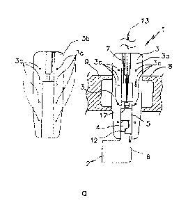
Fig. 1a shows a deployment unit 1 for an avalanche rescue system. Fig. 1a
shows
two handle holder elements 3a, 3b with complementary shapes. These can be
connected to one another by means of handle holder connections 3c arranged on
them, namely plug connections in this embodiment, which are plugged together
in
this embodiment. In the connected state, they form a handle holder 3 of the
deployment unit 1.
The internal structure of the handle holder 3 as well as components of the
deployment unit 1 contained in the handle holder 3 are described in greater
detail
below. To this end, the handle holder 3 is shown as open in Fig. 1a, i.e.,
handle
holder elements 3a, 3b that are not attached to one another are shown.
This shows first a schematically illustrated actuating handle 2 of the
deployment unit
1. A coupling piece 4, which engages with a coupling element 5 in a form-
fitting
manner, is arranged on the actuating handle 2. The coupling piece 4 and the
coupling element 5 are arranged in a coupling channel 6 formed by opposing
recesses in the two handle holder elements 3a, 3b. The coupling channel 6 is
designed to have a rectangular cross section, so that the coupling element 5
and the
coupling piece 4 are arranged in a rotationally fixed position in the coupling
channel
6.
CA 2971915 2017-06-27
- 10 -
The handle holder 3 is secured by means of a fixation section 8 on a carrier
system
9, in particular on a shoulder belt of a backpack, which serves as a carrier
system 9,
by using a strap.
Fig. la additionally shows that the coupling element 5 is connected to a cable
pull
nipple 17 of a cable pull 13. The cable pull 13 therefore leads through a
section of
the coupling element 5 and is secured by the cable pull nipple 17 in that the
cable
pull nipple 17 is supported on the coupling element 5. The coupling piece 4
and the
coupling element 5 are arranged displaceably in the coupling channel 6. The
cable
pull nipple 17 and the cable pull 13 are therefore entrained by the coupling
element 5
when the latter is displaced in the coupling channel 6.
The cable pull 13 may be connected to a function unit of the avalanche rescue
system. Due to the downward displacement of the coupling element 55 coupled to
the cable pull 13 ¨ in the diagram shown in Fig. la ¨ the function unit can be
triggered and/or activated.
Fig. la also shows that the handle holder 3 and/or the handle holder elements
3a, 3b
have an assembly aid borehole 7, which opens into the coupling channel 6. An
assembly aid pin through which the coupling element 5 can be shifted out of
the
coupling channel 6, for example, to establish a coupling connection between
the
coupling piece 4 and the coupling element 5, can be inserted through the
assembly
aid borehole 7. In this exemplary embodiment, the coupling element 5
additionally
has a catch section 12. The catch section 12 is designed so that the coupling
piece 4
can be pushed onto the coupling element 5 and then engages with it in a
coupling
connection. There are therefore various possibilities for establishing a
coupling
connection between the coupling piece 4 and the coupling element 5.
In alternative embodiments of the invention, it is provided that either an
assembly aid
channel 7 or a catch section 12 is formed in a deployment unit.
CA 2971915 2017-06-27
- 11
Fig. lb and Fig. 1 c now show the same deployment unit 1, but the handle
holder
element 3b is not illustrated in either figure for reasons of simplicity.
In particular Figs. lb and lc show two snapshots of the deployment unit 1
while with
the help of the actuating handle 2 the coupling piece 4 and the coupling piece
5 are
pulled out of the handle holder 3. Fig. lb therefore shows a position in which
the
coupling piece 4 and the coupling element 5 are still in the coupling channel
6.
However, Fig. lc illustrates a position, in which the coupling piece 4 has
already
exited from the coupling channel 6.
It can be seen here that, in the position shown in Fig. lc, the coupling
channel 6 no
longer holds the coupling connection between the coupling element 5 and the
coupling piece 4, in contrast with the positions illustrated in Figs. la and
lb. In the
position in Fig. lc, the coupling piece 4 can be released from the coupling
element 5
easily, reliably and with the least possible application of force, in
particular being
released automatically by further pulling on the actuating handle 2. In order
to further
facilitate the release of the connection, the coupling piece 4 and the
coupling
element 5 each have a bevel 11 in a coupling connection area 10. The bevel 11
is
oriented in such a way that when the coupling piece 4 is extracted and/or the
coupling element 5 is pulled out of the coupling channel 6, the coupling piece
4
slides away from the coupling element 5 laterally and thus the coupling
connection is
released automatically.
After releasing the coupling connection, the actuating handle 2 is thus freely
movable.
Furthermore, Fig. lc in combination with Fig. 1 a shows that the coupling
element 5 is
displaced by a preselectable deployment distance d. The length of the coupling
channel 6 is therefore selected so that the coupling element 5 can be
displaced at
least by the deployment distance d within the coupling channel 6 without
having to
release the coupling connection between the coupling piece 4 and the coupling
CA 2971915 2017-06-27
-12-
element 5. The coupling element 5 is therefore shifted at least by the
deployment
distance d before the coupling piece 4 and/or the actuating handle 2 is/are
uncoupled and/or enter(s) the corresponding position shown in Fig. 1c. This
ensures
that the cable pull 13 can also be displaced at least by the deployment
distance d.
Fig. 2 now shows a deployment device 30 with a deployment unit 20. The
deployment unit 20 in this exemplary embodiment corresponds to the deployment
unit 1. It differs only in the design of an alternative actuating handle 21.
This
actuating handle 21 has a mouthpiece 14 in particular. Therefore, after
releasing the
actuating handle 21, the mouthpiece 14 can be brought to the user's mouth
and/or to
the mouth of a person to be protected by the avalanche rescue system, and the
person can be supplied with air, for example. To this end, the actuating
handle 21 is
connected to a respiratory function unit by means of a tube (not shown).
This additionally shows that a resetting element 15, which puts the cable pull
13
under a prestress, is attached to the cable pull 13. The resetting element 15
is
therefore embodied as a spring element. The deployment distance d (Fig. 1c)
and
the minimum required force for deployment are predefined by the choice of the
spring hardness and the spring distance of the resetting element 15.
In addition, it can be seen that a function unit 16 is connected to the cable
pull 13.
The function unit 16 in this exemplary embodiment is designed as an avalanche
balloon 16b, which is connected to a pressurized gas cartridge 16a. The
function unit
16 here is equipped, so that the pressurized gas cartridge 16a is opened and
displacement of the cable pull 13 by the deployment distance d and the
avalanche
balloon 16b is inflated. In other words, the function unit 16 is deployed when
the
cable pull 13 is moved by the deployment distance d.
The present invention therefore makes it possible to pull the actuating handle
2
and/or the actuating handle 21 away from the deployment unit 1 and/or the
deployment unit 20 and thus to reliably deploy the function unit 16.
CA 2971915 2017-06-27
- 13 -
Since the coupling connection in particular does not require any demanding
mechanisms or the like, interference with the deployment unit, in particular
failure of
the function unit 16 to deploy can be effectively prevented even under the
most
adverse temperature conditions, etc.
CA 2971915 2017-06-27
-14-
List of Reference Numerals
1, 20 deployment unit
2, 21 actuating handle
3 handle holder
3a, 3b handle holder elements
3c handle holder connection
4 coupling piece
5 coupling element
6 coupling channel
7 assembly aid bore
8 fixation section
9 carrier system
10 coupling connection area
11 bevel
12 catch section
13 cable pull
14 mouthpiece
15 resetting element
16 function unit
16a pressurized gas cartridge
16b avalanche balloon
17 cable pull nipple
30 deployment device
deployment distance
CA 2971915 2017-06-27