Note: Descriptions are shown in the official language in which they were submitted.
HYDRAULIC FRACTURING SYSTEMS AND PROCESSES UTILIZING PORT
OBSTRUCTION DEVICES FOR SEATING ON PORTS OF A WELLBORE STRING
FIELD
[0001] The present disclosure relates to bodies, deployable by flowing
fluids, for closing
ports that are provided for effecting fluid communication between a wellbore
and a subterranean
formation.
BACKGROUND
[0002] Deployable bodies, are used for effecting zonal isolation within a
wellbore to enable
multi-stage fraccing. Such bodies are intended to provide zonal isolation to
enable targetted
treatment of the subterranean formation.
SUMMARY
[0003] In one aspect, there is provided a flow control apparatus
comprising: a housing; a
housing passage disposed within the housing; a plurality of ports extending
through the housing;
a flow control member, displaceable, relative to the ports, for effecting
opening of the ports;
wherein: the housing includes an external surface; a recessed channel defined
within the external
surface; and each one of the ports, independently, extends into the channel
such that fluid
conducted from the housing passage and through the ports is discharged from
the ports into the
channel.
[0004] In another aspect, there is provided a kit for implementation within
a wellbore for
control fluid communication between a wellbore and a subterranean formation,
comprising: a
flow control apparatus, wherein the flow control apparatus includes: a
housing; a housing
passage disposed within the housing; a plurality of ports extending through
the housing; a
plurality of seats, wherein each one of the seats is respective to a one of
the ports; a flow control
member, displaceable, relative to the ports, for effecting opening of the
ports; wherein: the
housing includes an external surface; a recessed channel defined within the
external surface; and
each one of the ports, independently, extends into the channel such that fluid
conducted from the
CAN_DMS \ 107708141 \ 1 1
CA 2971975 2017-06-27
housing passage and through the ports is discharged from the ports into the
channel; and a
plurality of port obstruction devices for seating on the seats.
[0005] In another aspect, there is provided a process for treating a
subterranean formation
comprising: opening at least one port of a wellbore string disposed within a
wellbore by
displacing a flow control member; conducting treatment material from the
wellbore to the
subterranean formation via the at least one port; and after the conducting of
treatment material,
seating a port obstruction device on each one of the at least one port, such
that each one of the at
least one port, independently, becomes closed.
[0006] In another aspect, there is provided a flow control apparatus
comprising: a housing; a
housing passage disposed within the housing; a seat; a port extending through
the housing; and a
retainer configured for retaining a port obstruction device to the flow
control apparatus.
BRIEF DESCRIPTION OF DRAWINGS
[0007] The preferred embodiments will now be described with the following
accompanying
drawings, in which:
[0008] Figure 1 is a schematic illustration of a system for effecting fluid
communication
between the surface and a subterranean formation via a wellbore;
[0009] Figure 2 is a sectional side elevation view of a flow control
apparatus for use in the
system illustrated in Figure 1, illustrating the ports in the closed
condition;
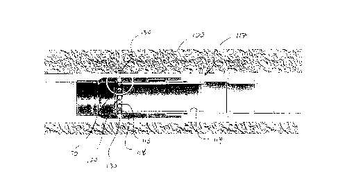
[0010] Figure 3 is a detailed view of detail "D" in Figure 2;
[0011] Figure 4 is a perspective view of a section of an external surface
of the flow control
apparatus, illustrating the recessed channel of the flow control apparatus;
[0012] Figure 5 is a side elevation view of a section of a wellbore string
of the system
illustrated in Figure 1, incorporating the flow control apparatus of Figure 2,
and disposed within
a wellbore, and illustrating port obstruction devices having been seated
within some of the ports
after the completion of a treatment operation (and after having the flow
control member
displaced to the open position);
CAN_DMS \107708141 \ 1 2
CA 2971975 2017-06-27
[0013] Figure 6 is a schematic illustration depicting the fluid flowpath
through a port where
the subterranean formation in the immediate vicinity of the port is resistant
to receiving flow of
fluid being conducted via the port;
[0014] Figure 7 is a detailed side elevation view of a portion of an
embodiment of a flow
control apparatus that is integratable within a wellbore string of the system
illustrated in Figure
1, with a retainer for retaining a port obstruction device within a port
obstruction device
receiving space for seating on a seat, with the port obstruction device being
seated on the seat;
[0015] Figure 8 is a detailed side elevation view of a portion of another
embodiment of a
flow control apparatus, that is integratable within a wellbore string of the
system illustrated in
Figure 1, with a retainer for retaining a port obstruction device within a
port obstruction device
receiving space for seating on a seat, with the port obstruction device being
seated on the seat;
[0016] Figure 9 is a sectional view of an embodiment of a flow control
apparatus that is
integratable within a wellbore string of the system illustrated in Figure 1,
showing the port
disposed in the closed condition, and with both of the flow control member and
the actuatable
valve disposed in the closed positions;
[0017] Figure 10 is a detailed view of Detail "A" in Figure 9;
[0018] Figure 11 is a sectional view of an embodiment of the flow control
apparatus
illustrated in Figure 10, showing the port disposed in the closed condition,
and with the
actuatable valve member disposed in the open position, and with the flow
control member
disposed in the closed position;
[0019] Figure 12 is a detailed view of Detail "B" in Figure 11;
[0020] Figure 13 is a sectional view of an embodiment of the flow control
apparatus
illustrated in Figure 9, showing the port disposed in the open condition, and
with both of the flow
control member and the actuatable valve disposed in the open positions;
[0021] Figure 14 is a detailed view of Detail "C" in Figure 13;
[0022] Figure 15 is a detailed view of Detail "D" in Figure 13;
CAN_DMS \107708141 \ 1 3
CA 2971975 2017-06-27
[0023]
Figure 16 is sectional view of a fragment of another embodiment of a flow
control
apparatus that is integratable within the wellbore string of the system
illustrated in Figure 1,
having an exploding bolt, illustrated prior to fracturing of the bolt; and
[0024]
Figure 17 is sectional view of a fragment of the embodiment of the flow
control
apparatus shown in Figure 16, illustrated after fracturing of the bolt.
DETAILED DESCRIPTION
[0025]
Referring to Figure 1, there is provided a wellbore material transfer system
104 for
conducting material to a subterranean formation 100 via a wellbore 102, from a
subterranean
formation 100 via a wellbore 102, or both to and from a subterranean formation
100 via a
wellbore 102. In some embodiments, for example, the subterranean formation 100
is a
hydrocarbon material-containing reservoir.
[0026]
In some embodiments, for example, the conducting (such as, for example, by
flowing) material to a subterranean formation 100 via a wellbore 102 is for
effecting selective
stimulation of a hydrocarbon material-containing reservoir. The stimulation is
effected by
supplying treatment material to the hydrocarbon material-containing reservoir.
In some
embodiments, for example, the treatment material is a liquid including water.
In some
embodiments, for example, the liquid includes water and chemical additives. In
other
embodiments, for example, the treatment material is a slurry including water,
proppant, and
chemical additives.
Exemplary chemical additives include acids, sodium chloride,
polyacrylamide, ethylene glycol, borate salts, sodium and potassium
carbonates, glutaraldehyde,
guar gum and other water soluble gels, citric acid, and isopropanol. In some
embodiments, for
example, the treatment material is supplied to effect hydraulic fracturing of
the reservoir. In
some embodiments, for example, the treatment material includes water, and is
supplied to effect
waterflooding of the reservoir.
[0027]
In some embodiments, for example, the conducting (such as, for example, by
flowing) material from a subterranean formation 100 via a wellbore 102 is for
effecting
production of hydrocarbon material from the hydrocarbon material-containing
reservoir. In
some of these embodiments, for example, the hydrocarbon material-containing
reservoir, whose
CAN_DMS \ 107708141 \ 1 4
CA 2971975 2017-06-27
hydrocarbon material is being produced by the conducting via the wellbore 102,
has been, prior
to the producing, stimulated by the supplying of treatment material to the
hydrocarbon material-
containing reservoir.
[0028] In some embodiments, for example, the conducting to the subterranean
formation 100
from the wellbore 102, or from the subterranean formation 100 to the wellbore
102, is effected
via one or more flow communication stations that are disposed at the interface
between the
subterranean formation 100 and the wellbore 102. In some embodiments, for
example, the flow
communication stations are integrated within a wellbore string 116 that is
deployed within the
wellbore 102. Integration may be effected, for example, by way of threading or
welding.
[00291 The wellbore string 116 includes one or more of pipe, casing, and
liner, and may also
include various forms of tubular segments, such as the flow control
apparatuses 115A described
herein. The wellbore string 116 defines a wellbore string passage 119. In some
embodiments,
for example, the flow communication station is integratable within the
wellbore string 116 by a
threaded connection.
[0030] Successive flow communication stations 115 may be spaced from each
other along
the wellbore string 116 such that each flow communication stations 115 is
positioned adjacent a
zone or interval of the subterranean formation 100 for effecting flow
communication between the
wellbore 102 and the zone (or interval)..
[0031] For effecting the flow communication, the fluid communication
station 115 includes a
flow control apparatus 117. Referring to Figures 2 to 6, the flow control
apparatus 117 includes
one or more ports 118 through which the conducting of the material is
effected. The ports 118
are disposed within a sub that has been integrated within the wellbore string
116, and are pre-
existing, in that the ports 118 exist before the sub, along with the wellbore
string 116, has been
installed downhole within the wellbore string 116.
[0032] The flow control apparatus 117 includes a flow control member 114
for controlling
the conducting of material by the flow control apparatus 117 via the one or
more ports 118. The
flow control member 114 is displaceable, relative to the one or more ports
118, for effecting
opening of the one or more ports 118. In some embodiments, for example, the
flow control
CAN_DMS \107708141\1 5
CA 2971975 2017-06-27
member 114 is also displaceable, relative to the one or more ports 118, for
effecting closing of
the one or more ports 118. In this respect, the flow control member 114 is
displaceable such that
the flow control member 114 is positionable between open and closed positions.
The open
position of the flow control member 114 corresponds to an open condition of
the one or more
ports 118. The closed position of the flow control member 114 corresponds to a
closed condition
of the one or more ports 118.
[0033] In some embodiments, for example, the flow control member 114 is
displaceble
mechanically, such as, for example, with a shifting tool. In some embodiments,
for example, the
flow control member 114 is displaceable hydraulically, such as, for example,
by communicating
pressurized fluid via the wellbore to urge the displacement of the flow
control member 14. In
some embodiments, for example, the flow control member 114 is integrated
within a flow
control apparatus which includes a trigger for effecting displacement of the
flow control member
114 hydraulically in response to receiving of a signal transmitted from the
surface 10.
[0034] In some embodiments, for example, in the closed position, the one or
more ports 118
are covered by the flow control member 114, and the displacement of the flow
control member
114 to the open position effects at least a partial uncovering of the one or
more ports 118 such
that the 118 becomes disposed in the open condition. In some embodiments, for
example, in the
closed position, the flow control member 114 is disposed, relative to the one
or more ports 118,
such that a sealed interface is disposed between the wellbore string 116 and
the subterranean
formation 100, and the disposition of the sealed interface is such that the
conduction of material
between the wellbore string 116 and the subterranean formation 100, via the
fluid
communication station 115 is prevented, or substantially prevented, and
displacement of the flow
control member 114 to the open position effects flow communication, via the
one or more ports
118, between the wellbore string 116 and the subterranean formation 100, such
that the
conducting of material between the wellbore string 116 and the subterranean
formation 100, via
the flow communication station, is enabled. In some embodiments, for example,
the sealed
interface is established by sealing engagement between the flow control member
114 and the
wellbore string 116. In some embodiments, for example, the flow control member
114 includes
a sleeve. The sleeve is slideably disposed within the wellbore string passage
119.
CAN_DMS \ 107708141 \ 1 6
CA 2971975 2017-06-27
[0035] Each one of the ports 118, independently, is disposed for being at
least partially
occluded by a port obstruction device 130. Suitable port obstruction devices
130 include, for
example, ball sealers. In some embodiments, for example, the hydrocarbon
material-containing
reservoir is stimulated by the supplying of treatment material to the
hydrocarbon material-
containing reservoir via the ports 118, and after sufficient treatment
material has been supplied to
the hydrocarbon material-containing reservoir via the ports 118, port
obstruction devices 130 are
deployed downhole for seating within the ports 118.
[0036] In this respect, in some embodiments, for example, for each one of
the ports 118,
independently, a seat 1180, for seating of a port obstruction device 130, is
disposed relative to
the port 118 such that seating of the port obstruction device 130 effects at
least partial occlusion
of the port 118. In some embodiments, for example, the seat 1180 is disposed
peripherally about
the port 118. In some embodiments, for example, the port 118 is disposed
within the seat 1180.
In some embodiments, for example, the seating of the port obstruction device
130 on the seat
1180 effects sealing engagement of the port obstruction device 130 to the seat
1180, such that a
sealing interface is established, and such that the port 118 is sealed or
substantially sealed.
[0037] In this respect, there is provided a process including: after the
conducting of fluid
through an opened port 118 during a treatment operation, seating of the port
obstruction device
130 against the seat 1180 such that the closing of the opening 102 is
effected. In some
embodiments, for example, the seating of the port obstruction device 130 on
the seat 1180 is
effected by landing of the port obstruction device 130 on the seat 1180 by
conducting the port
obstruction device 130 downhole with fluid that is supplied to and is flowing
within the wellbore
102. In some embodiments, for example, prior to the conducting of fluid
through the opened
port 118, the port 118 is closed, and opening of the port 118 is effected by
displacing the flow
control member 114 from the closed position to the open position. In some
embodiments, for
example, prior to the seating of the port obstruction device 130 on the seat
1180 by conducting
the port obstruction device 130 downhole with fluid that is supplied to and is
flowing within the
wellbore 102, the pressure of the fluid that is supplied and flowed, for
conducting the port
obstruction device, is less than the pressure of the fluid being conducted
through the opened port
118 during a treatment operation. In some embodiments, this reduced pressure
mitigates the risk
CAN_DMS \ 107708141 \1 7
CA 2971975 2017-06-27
of having the port obstruction device 130 overshoot and flow past the seat
1180, due to its own
inertia.
[0038] In some embodiments, for example, the flow control member 114 is
displaceable
from a closed position to an open position for effecting opening of the port
118, but is not
designed to return to the closed position. Examples of a the flow control
member 114 is not
designed to return to the closed position include at least some kinds of "toe
valves" or "toe
sleeves". In other embodiments, upon the flow control member 114 becoming
disposed in the
open position, attempts to close the flow control member 114 are unsuccessful.
[0039] After a treatment operation, involving the conducting of fluid via
the port 118 (such
as, for example, the supplying of treatment fluid into the subterranean
formation 100, such as, for
example, during a hydraulic fracturing operation) has been effected, it may be
desirable to close
the port 118, at least temporarily (such as, for example, to enable supplying
of treatment fluid
into the subterranean formation via another fluid communication station, such
another fluid
communication station that is disposed uphole), with the intention of later re-
opening the port
118 (such as, for example, in order to receive production of reservoir fluids,
from the
subterranean formation 100, within the wellbore 102).
[0040] In this respect, a process is provided and includes displacing a
flow control member
114 for effecting opening of a port 118 within a wellbore 102, conducting
fluid via the opened
port 118, and, after the conducting, seating a port obstruction device 130 on
the seat 1080 such
that the port 118 becomes closed. In some embodiments, for example, the
seating of a port
obstruction device 130 is such that fluid communication between the surface
and the
subterranean formation, via the port 118, becomes sealed or substantially
sealed.
[0041] After the port obstruction device 130 has been seated on the seat
1180 for a sufficient
period of time (such as, for example, for a period of time sufficient to
enable supplying of
treatment fluid to the subterranean formation via other fluid communication
stations), an opening
of the port 118 is effected.
[0042] In some embodiments, for example, the opening is effected by an
unseating of the
port obstruction device 130, such as, for example, by effecting a pressure
reduction within the
CAN_DMS \107708141 \ 1 8
CA 2971975 2017-06-27
wellbore. In some embodiments, for example, the pressure reduction,
additionally effects
flowback of the port obstruction device 130.
[0043] In some embodiments, for example, the opening is effected after the
port obstruction
device 130 has been seated on the seat 1080 for a sufficient time in contact
with wellbore fluids
within the wellbore 102 such that a change in condition of the port
obstruction device 130 is
effected (in response to the contacting with the wellbore fluids) such that a
fluid passage is
established within the port obstruction device 130 such that fluid
communication is effected
between the surface and the subterranean formation via the port 118. In some
of these
embodiments, for example, at least a portion of the port obstruction device
130 is dissolvable in
wellbore fluids within the wellbore 102 and, in this respect, the change in
condition includes
dissolution of at least a portion of the port obstruction device 130 such that
the fluid passage
becomes established.
[0044] Referring to Figures 2 to 6, in some embodiments, for example, the
fluid
communication station includes a flow control apparatus 117, and the flow
control apparatus 117
includes a housing 122, a housing passage 124 disposed within the housing 122,
the flow control
member 114, a plurality of ports 118, and a plurality of seats 1180, wherein
each one of the seat
1180 is associated with a respective one of the ports 118. The housing 122
includes an external
surface 122A, and a recessed channel 126 is defined within the external
surface 122A (see Figure
4). Each one of the ports 118, independently, extends into the channel 126
such that fluid
conducted from the wellbore 102 to the subterranean formation via the ports
118 is discharged
from the ports 118 into the channel 126. In some embodiments, for example, the
minimum
depth of the channel 126 is at least 0.1 inches. In some embodiments, for
example, the minimum
cross-sectional area of the channel is at least 0.01 square inches.
[0045] In some embodiments, for example, the channel 126 receives flow of
fluid conducted,
via one or more ports 118, which would otherwise be at least impeded (and, in
some
embodiments, blocked) in cases where the portion of the formation in the
immediate vicinity of
the one or more ports 118 is resistant to receiving flow of fluid being
conducted via the one or
more ports 118 (for example, such formation portion is resistant to fracturing
effected by fluid
being communicated through the one or more ports). If such flow of fluid is at
least impeded
CAN_DMS \107708141\1 9
CA 2971975 2017-06-27
(and, in some embodiments, blocked), the seating of the port obstruction
device 130 may not
occur. By providing the channel 126, there is a greater likelihood that fluid
will flow through a
port 118 where the portion of the formation in the immediate vicinity of the
port 118 is resistant
to receiving flow of fluid being conducted via the port 118. This is because
the channel 126
provides greater opportunity for fluid being communicated to the port 118 to
be conducted to
another portion of the formation which is less resistant to receiving flow of
fluid from the
wellbore 102. This phenomenon is illustrated in Figure 6, where port
obstruction devices 130
have been seated within ports 118A, 118B, and 118D, but the port 118C has yet
to be closed
with a corresponding port obstruction device, and the portion 130X of the
formation 130 in the
immediate vicinity of the port 118C is resistant to receiving fluid flow.
Because the channel 126
has been provided, a flow path is establishable through the port 118C, by
enabling fluid
communication with the portion 130A, of the formation 130, which is able to
receive fluid flow,
thereby enabling the seating of a port obstruction device within the port
118C.
[0046] In some embodiments, for example, the flow control apparatus 117
includes one or
more ports 118, and while each one of the one or more ports 118 are closed,
independently, by a
corresponding port obstruction device 130 (seated on a respective seat 1180),
fluid pressure
within the wellbore 102 is maintained above a minimum predetermined pressure
such that a port
obstruction devices 130 remains seated on a respective seat 1180 of each one
of the one or more
ports 118. In some of these embodiments, for example, while seating of a port
obstruction
devices 130 on a respective seat 1180 of each one of the one or more ports 118
is being
maintained by fluid pressure within the wellbore 102, a flow control member
114 of another
fluid communication station (such as, for example, another fluid communication
station that is
disposed uphole of the flow communication station whose one or more ports 118
are each,
independently, closed by a corresponding port obstruction device 130 that is
seated on a
respective seat 1180 of each one of the one or more ports 118) is displaced,
relative to its
corresponding one or more ports 118, from the closed position to the open
position such that its
corresponding one or more ports 118 becomes opened and conducts fluid from the
wellbore 102
to the subterranean formation 100. In some embodiments, for example, the fluid
pressure
continues being maintained above the minimum predetermined pressure as the one
or more ports
118 of the another fluid communication station is being opened. In this
respect, in some
embodiments, for example, after having supplied fluid to the subterranean
formation via the one
CAN_DMS \ 107708141 \ 1 10
CA 2971975 2017-06-27
or more ports 118 of a first communication station, and while the fluid
pressure is maintained
above a minimum predetermined pressure within the wellbore 102, seating of the
port
obstruction device 130 on a respective seat 1180 of each one of the one or
more ports 118 of the
first fluid communication station is effected, and after the effecting of the
seating of the port
obstruction device 130 on a respective seat 1180 of each one of the one or
more ports 118 of a
first fluid communication station, the flow control member 114 of a second
fluid communication
station is displaced to an open position such that the one or more ports 118
of the second fluid
communication station becomes opened and fluid is supplied to the subterranean
formation via
the one or more ports 118 of the second fluid communication station. In some
embodiments, for
example, after the supplying of fluid into the subterranean formation via the
one or more ports
118 of the second fluid communication station, at least one port obstruction
device 130, for each
one of the one or more ports 118 of the second fluid communication station, is
deployed
downhole such that a port obstruction device 130 becomes seated on a
respective seat 1080 of
each one of the one or more ports of the second fluid communication station
such that the one or
more ports 118 of the second fluid communication station becomes closed. In
some
embodiments, for example, the seating of a port obstruction device 130 on a
respective seat 1080
of each one of the one or more ports 118 of the second fluid communication
station is such that
fluid communication between the surface and the subterranean formation, via
the one or more
ports 118 of the second fluid communication station, becomes sealed or
substantially sealed. In
some embodiments, for example, the second fluid communication station is
disposed uphole
relative to the first fluid communication station.
100471 In some embodiments, for example, the flow control apparatus 117
includes a retainer
132 configured for retaining a port obstruction device 130 to the flow control
apparatus 117. In
those embodiments where the flow control apparatus 117 includes more than one
port 118, in
some of these embodiments, for example, the retainer 132 is configured for
retaining a port
obstruction device 130 for seating on a respective seat 1080 of each one of
the ports 118.
[0048] In some embodiments, for example, the retainer 132 is sufficiently
pliable such that a
port obstruction device 130, in response to application of a sufficient fluid
pressure differential,
is conductible past the retainer 132 and into a port obstruction device
receiving space 134.
While within the port obstruction device receiving space 134, the port
obstructions device 130 is
CAN_DMS \ 107708141 \ 1 11
CA 2971975 2017-06-27
disposed for seating on a seat 1180 of a port 118 for effecting closure of the
port 118. In some
embodiments, for example, the retainer 132 is in the form of a c-ring that is
coupled to the body
136 of the apparatus 117. In some embodiments, for example, the retainer 132
is in the form of a
canted coil spring that is coupled to the body 136 of the apparatus 117.
[0049] Referring to Figure 7, in some embodiments, for example, upon
disposition of the
port obstructions device 130 within the port obstruction device receiving
space 134, the port
obstruction device 130 becomes seated on a seat 1180 of a port 118 such that
closure of the port
118 is effected. Referring to Figure 8, in some embodiments, for example, upon
disposition of
the port obstructions device 130 within the port obstruction device receiving
space 134, the port
obstruction device 130 is disposed for seating on a seat 1180 of a port 118 in
response to
application of a sufficient fluid pressure differential such that, upon the
seating of the port
obstruction device 130 on the seat 1180, closure of the port 118 is effected.
[0050] In those embodiments where, upon disposition of the port
obstructions device 130
within the port obstruction device receiving space 134, the port obstruction
device 130 becomes
seated on a seat 1180 of a port 118 such that closure of the port 118 is
effected, the port
obstruction device 130 and the flow control apparatus 117 are co-operatively
configured such
that, after the port obstruction device 130 has been disposed in contact with
subterranean fluids
(from within the wellbore, or external to the wellbore, or both) for a
sufficient period of time,
while being disposed within the port obstruction device receiving space 134,
such that material
degradation (such as, for example, by at least one of dissolution, chemical
reaction, or
disintegration) of the port obstruction device 130 is effected, an opening of
the port 118 is
effected. In this respect, in some embodiments, for example, the port
obstruction device 130
includes polystyrene which thereby renders the port obstruction device
degradable in the
presence of wellbore fluids.
[0051] In those embodiments where, upon disposition of the port
obstructions device 130
within the port obstruction device receiving space 134, the port obstruction
device 130 becomes
disposed for seating on a seat 1180 of a port 118 in response to application
of a sufficient fluid
pressure differential such that, upon the seating of the port obstruction
device 130 on the seat
1180, closure of the port 118 is effected, the port obstruction device 130 and
the flow control
CAN_DMS \ 107708141 \ 1 12
CA 2971975 2017-06-27
apparatus 117 are co-operatively configured such that, after the port
obstruction device 130 has
become seated on a seat 1180 of a port 118, and a pressure differential is
applied while the port
obstructions device 130 is seated on the seat 1180 of the port 118 such that
the port obstruction
device 130 is displaced from the seat 1180 (and thereby becomes unseated
relative to the seat
1180), opening of the port 118 is effected.
[0052] Referring to Figures 9 to 15, in some embodiments, for example, the
flow control
member 114 is integrated within a flow control apparatus 310 and includes a
fluid responsive
surface 120 for receiving communication of a pressurized fluid for urging the
displacement of
the flow control member 114 between the closed and open positions, and the
flow control
apparatus 310 further includes a sensor 326, a housing 312, and a trigger 313.
The housing 312
includes a housing passage 316, and the housing 312 is integratable within the
wellbore string
200, such as by a threaded connection. The trigger 313 is responsive to the
sensing of a trigger-
actuating ("TI") signal by the sensor, with effect that fluid communication is
established between
the housing passage 316 and the fluid responsive surface 120 in response to
the sensing of a
trigger-actuating ("TI") signal by the sensor 326. In this respect, while the
flow control
apparatus 310 is integrated within the wellbore string 200 as part of a fluid
communication
station 115 such that the housing passage 316 is disposed in fluid
communication with the
surface via the wellbore 100, and while a TI signal is being transmitted (such
as, for example, via
the wellbore), in response to the sensing of the TI signal by the sensor 326,
fluid communication
between the surface and the fluid responsive surface 120, via the wellbore
100, is established by
the trigger 313.
100531 In some embodiments, for example, the TI signal is transmitted
through the wellbore
100. In some of these embodiments, for example, the TI signal is transmitted
via fluid disposed
within the wellbore 100.
[0054] In some embodiments, for example, the sensor 326 is a pressure
sensor, and the
actuating signal is one or more pressure pulses. An exemplary pressure sensor
is a Kellar
Pressure Transducer Model 6LHP/81188TM.
100551 Other suitable sensors may be employed, depending on the nature of
the signal being
used for the actuating signal. Other suitable sensors include a Hall effect
sensor, a radio
CAN_DMS \107708141\1 13
CA 2971975 2017-06-27
frequency identification ("RF1D") sensor, or a sensor that can detect a change
in chemistry (such
as, for example, pH), or radiation levels, or ultrasonic waves.
[0056] In some embodiments, for example, the TI signal is one or more
pressure pulses. In
some embodiments, for example, the TI signal is defined by a pressure pulse
characterized by at
least a magnitude. In some embodiments, for example, the pressure pulse is
further
characterized by at least a duration. In some embodiments, for example, the TI
signal is defined
by a pressure pulse characterized by at least a duration.
[0057] In some embodiments, for example, the TI signal is defined by a
plurality of pressure
pulses. In some embodiments, for example, the TI signal is defined by a
plurality of pressure
pulses, each one of the pressure pulses characterized by at least a magnitude.
In some
embodiments, for example, the TI signal is defined by a plurality of pressure
pulses, each one of
the pressure pulses characterized by at least a magnitude and a duration. In
some embodiments,
for example, the TI signal is defined by a plurality of pressure pulses, each
one of the pressure
pulses characterized by at least a duration. In some embodiments, for example,
each one of
pressure pulses is characterized by time intervals between the pulses.
[0058] In some embodiments, for example, the sensor 326 is disposed in
communication
within the wellbore 100, and the TI signal is being transmitted within the
wellbore 100, such that
the sensor 326 is disposed for sensing the TI signal being transmitted within
the wellbore 100. In
some embodiments, for example, the sensor 326 is disposed within the wellbore
100. In this
respect, in some embodiments, for example, the sensor 326 is mounted to the
housing 112 within
a hole that is ported to the wellbore 200, and is held in by a backing plate
that is configured to
resist the force generated by pressure acting on the sensor 326.
[0059] In some embodiments, for example, the sensor 326 is configured to
receive a signal
generated by a seismic source . In some embodiments, for example, the seismic
source includes
a seismic vibrator unit. In some of these embodiments, for example, the
seismic vibration unit is
disposed at the surface 10.
[0060] In some embodiments, for example, the flow control apparatus 310
further includes a
sealing interface 315, and the trigger 313 includes an actuator 322 for
defeating the sealing
CAN_DMS \107708141\1 14
CA 2971975 2017-06-27
interface 315. In this respect, the actuator 322 is responsive to sensing of
the TI signal by the
sensor 326. for defeating the sealing interface 315 such that the
establishment of fluid
communication between the housing passage 316 and the fluid responsive surface
120 is
effected.
[0061] In some embodiments, for example, the flow control apparatus 310
further includes a
valve 324, and the sealing interface 315 is defined by a sealing, or
substantially sealing,
engagement between the valve 324 and the housing 312. In some embodiments, for
example, the
sealing interface 315 is defined by sealing members 315A (such as, for
example, o-rings) carried
by the valve 324. In this respect, the change in condition of the sealing
interface 315 is effected
by a change in condition of the valve 324. Also in this respect, the actuator
322 is configured to
effect a change in condition of the valve 324 (in response to the sensing of
the TI signal by the
sensor 326) such that there is a loss of the sealing, or substantially
sealing, engagement between
the valve 324 and the housing 312, such that the sealing interface 315 is
defeated, and such that
fluid communication between the housing passage 316 and the fluid responsive
surface 120 is
established.
[0062] In some embodiments, for example, the valve 324 is displaceable, and
the change in
condition of the valve 324, which the actuator 322 is configured to effect in
response to the
sensing of a TI signal by the sensor 326, includes displacement of the valve
324. In this respect,
the actuator 322 is configured to effect displacement of the valve 324 such
that the sealing
interface 315 is defeated and such that fluid communication between the
housing passage 316
and the fluid responsive surface 120 is established.
[0063] In some embodiments, for example, the flow control apparatus 310
further includes a
passageway 326. The valve 324 and the passageway 326 are co-operatively
disposed such that
fluid communication between the housing passage 316 and the fluid responsive
surface 120 is
established in response to the displacement of the valve 324, which is
effected in response to the
sensing of the TI signal by the sensor 326. In this respect, the establishing
of the fluid
communication between the housing passage 316 and the fluid responsive surface
120 is
controlled by the positioning of the valve 324 within the passageway 326. In
this respect, the
valve 324 is configured for displacement relative to the passageway 326. In
some embodiments,
CAN_DMS \107708141 \ 1 15
CA 2971975 2017-06-27
for example, the valve 324 includes a piston. The displacement of the valve
324 is from a closed
position (see Figures 7 and 8) to an open position (see Figures 9 and 10). In
some embodiments,
for example, when disposed in the closed position, the valve 324 is occluding
the passageway
326. In some embodiments, for example, when the valve 324 is disposed in the
closed position,
sealing, or substantial sealing, of fluid communication, between the housing
passage 316 and the
fluid responsive surface 120 is effected. When the valve 324 is disposed in
the open position,
fluid communication is effected between the housing passage 316 and the fluid
responsive
surface 120.
[0064] In some embodiments, for example, the passageway 326 extends through
the flow
control member 114, and the valve 324 is disposed in a space within the flow
control member
114, such that the displacement of the valve 324 is also relative to the flow
control member 114.
[0065] In some embodiments, for example, the actuator 322 includes an
electro-mechanical
trigger, such as a squib. The squib is configured to, in response to the
signal received by the
sensor 326, effect generation of an explosion. In some embodiments, for
example, the squib is
mounted within the body such that the generated explosion effects the
displacement of the valve
324. Another suitable actuator 322 is a fuse-able link or a piston pusher.
[0066] In some embodiments, for example, the flow control apparatus 310
further includes
first and second chambers 334, 336. The first chamber 334 is disposed in fluid
communication
with the fluid responsive surface 120 for receiving pressurized fluid from the
housing passage
316, and the second chamber 336 is configured for containing a fluid and
disposed relative to the
flow control member 114 such that fluid contained within the second chamber
336 opposes the
displacement of the flow control apparatus 310 that is being urged by
pressurized fluid within the
first chamber 334, and the displacement of the flow control member 114 is
effected when the
force imparted to the flow control member 114 by the pressurized fluid within
the first chamber
334 exceeds the force imparted to the flow control member by the fluid within
the second
chamber 336. In some embodiments, for example, the displacement of the flow
control member
114 is effected when the pressure imparted to the flow control member 114 by
the pressurized
fluid within the first chamber 334 exceeds the pressure imparted to the flow
control member 114
by the fluid within the second chamber 336.
CAN_DMS \107708141\1 16
CA 2971975 2017-06-27
[0067] In some embodiments, for example, both of the first and second
chambers 334, 336
are defined by respective spaces interposed between the housing 312 and the
flow control
member 114, and a chamber sealing member 338 is also included for effecting a
sealing interface
between the chambers 334, 336, while the flow control member 114 is being
displaced to effect
the opening of the port 318.
[0068] In some embodiments, for example, to mitigate versus inadvertent
opening, the valve
324 may, initially, be detachably secured to the housing 312, in the closed
position. In this
respect, in some embodiments, for example, the detachable securing is effected
by a shear pin
configured for becoming sheared, in response to application of sufficient
shearing force, such
that the valve 324 becomes movable from the closed position to the open
position. In some
embodiments, for example, the shearing force is effected by the actuator 312..
[0069] In some embodiments, for example, to prevent the inadvertent opening
of the valve
324, the valve 324 may be biased to the closed position, such as by, for
example, a resilient
member such as a spring. In this respect, the actuator 322 used for effecting
opening of the valve
324 must exert sufficient force to at least overcome the biasing force being
applied to the valve
324 that is maintaining the valve 324 in the closed position.
[0070] In some embodiments, for example, to prevent the inadvertent opening
of the valve
324, the valve 324 may be pressure balanced such that the valve 324 is
disposed in the closed
position.
[0071] In some embodiments, for example, the flow control apparatus 310
further includes a
controller. The controller is configured to receive a sensor-transmitted
signal from the sensor
326 upon the sensing of the TI signal and, in response to the received sensor-
transmitted signal,
supply a transmitted signal to the trigger 313. In some embodiments, for
example, the controller
and the sensor 326 are powered by a battery that is disposed on-board within
the flow control
apparatus 310. Passages for wiring for electrically interconnecting the
battery, the sensor, the
controller and the trigger are also provided within the apparatus 310.
[0072] Referring to Figures 14 and 15, in some embodiments, for example,
the flow control
member 114 is integrated within a flow control apparatus 410 that includes a
sensor 426, and the
CAN_DMS \ 107708141 \1 17
CA 2971975 2017-06-27
flow control member 114 is displaceable from the closed position to the open
position in
response to urging by a pressurized fluid that is communicated to the flow
control member after
the defeating of a sealing interface 415, the defeating of the sealing
interface 415 being actuated
by communication of a pressurized fluid while the sealing interface 415 is
disposed in a
defeatable condition, the sealing interface 415 having become disposed in the
defeatable
condition in response to the sensing of a sealing interface actuation ("SIA")
signal by the sensor
426.
[0073] In some embodiments, for example, the SIA signal is transmitted
through the
wellbore 100. In some of these embodiments, for example, the SIA signal is
transmitted via
fluid disposed within the wellbore 100.
[0074] In some embodiments, for example, the sensor 426 is a pressure
sensor, and the
actuaSIAng signal is one or more pressure pulses. An exemplary pressure sensor
is a Kellar
Pressure Transducer Model 6LHP/81188TM.
[0075] Other suitable sensors may be employed, depending on the nature of
the signal being
used for the actuang signal. Other suitable sensors include a Hall effect
sensor, a radio frequency
idenfication ("RFID") sensor, or a sensor that can detect a change in
chemistry (such as, for
example, pH), or radiation levels, or ultrasonic waves.
[0076] In some embodiments, for example, the SIA signal is one or more
pressure pulses. In
some embodiments, for example, the SIA signal is defined by a pressure pulse
characterized by
at least a magnitude. In some embodiments, for example, the pressure pulse is
further
characterized by at least a duration. In some embodiments, for example, the
SIA signal is
defined by a pressure pulse characterized by at least a duration.
[0077] In some embodiments, for example, the SIA signal is defined by a
plurality of
pressure pulses. In some embodiments, for example, the SIA signal is defined
by a plurality of
pressure pulses, each one of the pressure pulses characterized by at least a
magnitude. In some
embodiments, for example, the SIA signal is defined by a plurality of pressure
pulses, each one
of the pressure pulses characterized by at least a magnitude and a duration.
In some
embodiments, for example, the SIA signal is defined by a plurality of pressure
pulses, each one
CAN_DMS \107708141\1 18
CA 2971975 2017-06-27
of the pressure pulses characterized by at least a duration. In some
embodiments, for example,
each one of pressure pulses is characterized by time intervals between the
pulses.
[0078] In some embodiments, for example, the sensor 426 is disposed in
communication
within the wellbore 100, and the SIA signal is being transmitted within the
wellbore 100, such
that the sensor 426 is disposed for sensing the SIA signal being transmitted
within the wellbore
100. In some embodiments, for example, the sensor 426 is disposed within the
wellbore 100. In
this respect, in some embodiments, for example, the sensor 426 is mounted to
the housing 412
within a hole that is ported to the wellbore 200, and is held in by a backing
plate that is
configured to resist the force generated by pressure acting on the sensor 426.
[0079] In some embodiments, for example, the sensor 426 is configured to
receive a signal
generated by a seismic source . In some embodiments, for example, the seismic
source includes
a seismic vibrator unit. In some of these embodiments, for example, the
seismic vibration unit is
disposed at the surface 10.
[0080] In this respect, in some embodiments, for example, the flow control
member 114
includes a fluid responsive surface 120 for receiving communication of a
pressurized fluid for
urging displacement of the flow control member 114. As well, the flow control
apparatus 410
includes a housing 412 that is integratable within the wellbore string 200 as
part of a fluid
communication station 115, such as by a threaded connection, and a housing
passage 416 is
defined within the housing 412. The flow control apparatus 410 also includes a
sealing interface
415 and an actuator 422. The actuator 422 is responsive to sensing of the SIA
signal by the
sensor 426, for changing a condition of the sealing interface 415 such that
the sealing interface
415 becomes disposed in a defeatable condition such that, in response to
receiving
communication of a pressurized fluid, the sealing interface 415 is defeated
and such that fluid
communication is established between the housing passage 416 and the fluid
responsive surface
420.
[0081] In some embodiments, for example, the flow control apparatus further
includes a
valve 424, and the sealing interface 415 is defined by sealing, or
substantially sealing,
engagement between the valve 424 and the housing 412. In this respect, the
change in condition
of the sealing interface 415 is effected by a change in condition of the valve
424. Also in this
CAN_DMS \ 107708141 \ 1 19
CA 2971975 2017-06-27
respect, the actuator 422 is configured to effect a change in condition of the
valve 424 (in
response to the sensing of the signal by the sensor 426) such that the sealing
interface 415
becomes disposed in the defeatable condition. In this respect, while the
sealing interface 415
(defined by the sealing, or substantially sealing, engagement between the
valve 424 and the
housing 412) is disposed in the defeatable condition (the defeatible condition
having been
effected in response to the change in condition of the valve 424, as above-
described), in response
to receiving communication of a pressurized fluid, there is a loss of the
sealing, or substantially
sealing, engagement between the valve 424 and the housing 412. As a result,
there is a loss of
sealing, or substantially sealing, engagement between the valve 424 and the
housing 412, such
that the sealing interface 415 is defeated, and such that fluid communication
is established
between the housing passage 416 and the fluid responsive surface 420.
[0082] In some embodiments, for example, the valve 424 includes a valve
sealing surface
424A configured for effecting the sealing, or substantially sealing,
engagement between the
valve 424 and the housing 412. In this respect, the sealing, or substantially
sealing, engagement
between the valve 424 and the housing 412 is effected by the sealing, or
substantially sealing,
engagement between the valve sealing surface 424A and a housing sealing
surface 412A. Also
in this respect, the change in condition of the valve 424 is such that the
valve sealing surface
424A becomes displaceable relative to the housing sealing surface 412A for
effecting a loss of
the sealing, or substantially sealing, engagement between the valve sealing
surface 424A and the
housing sealing surface 412A, such that the sealing interface 415 is defeated
and such that fluid
communication is established between the housing passage 416 and the fluid
responsive surface
420. Also in this respect, the loss of the sealing, or substantially sealing,
engagement between
the valve 424 and the housing 412, that is effected in response to receiving
communication of a
pressurized fluid while the valve 424 is disposed such that the valve sealing
surface 424A is
displaceable relative to the housing sealing surface 412A, includes the loss
of the sealing, or
substantially sealing, engagement between the valve sealing surface 424A and
the housing
sealing surface 412A.
100831 In some embodiments, for example, the flow control apparatus 410
further includes a
passageway 427, and the passageway extends between the housing passage 412 and
the fluid
responsive surface 420. The valve 424 and the passageway 427 are co-
operatively disposed such
CAN_DMS \107708141 \ 1 20
CA 2971975 2017-06-27
that the fluid communication between the housing passage 416 and the fluid
responsive surface
420 is established in response to the displacement of the valve 424 relative
to the passageway
427, effected in response to the sensing of the SIA by the sensor 426.
Sealing, or substantial
sealing, of the passageway 427 is effected by the sealing or substantially
sealing, engagement
between the valve 424 and the housing 412 (and, in some embodiments, for
example, the valve
sealing surface 424A and the housing sealing surface 412A). Also in this
respect, sealing, or
substantially sealing, of fluid communication between the housing passage 412
and the fluid
responsive surface 420 is effected by the sealing or substantially sealing,
engagement between
the valve 424 and the housing 412 (and, in some embodiments, for example, the
valve sealing
surface 424A and the housing sealing surface 412A).
[0084] In some embodiments, for example, the actuator 422 includes a squib,
and the change
in condition of the sealing interface 415 (and also, in some embodiments, for
example, the valve
424) is effected by an explosion generated by the squib in response to sensing
of the signal by
the sensor 426. In some embodiments, for example, the squib is suitably
mounted within the
housing 412 to apply the necessary force to the valve 424. Another suitable
valve actuator 42 is
a fuse-able link or a piston pusher.
[0085] In some embodiments, for example, the change in condition of the
valve 424 includes
a fracturing of the valve 424. In the embodiment illustrated in Figure 15, the
fracture is
identified by reference numeral 452. In some embodiments, for example, while
the valve 424 is
disposed in a fractured condition, in response to receiving communication of a
pressurized fluid,
a loss of the sealing, or substantially sealing, engagement between the valve
424 and the housing
412 is effected, such that there is an absence of sealing, or substantially
sealing, engagement
between the valve 424 and the housing 412, and such that the sealing interface
415 is defeated
and such that fluid communication is established between the housing passage
416 and the fluid
responsive surface 420.
[0086] In those embodiments where the change in condition of the valve 424
includes a
fracturing of the valve 424, in some of these embodiments, for example, the
valve 424 includes a
coupler 424B that effects coupling of the valve 424 to the housing 412 while
the change in
condition is effected. In some embodiments, for example, the coupler 424B is
threaded to the
CAN_DMS \107708141 \ 1 21
CA 2971975 2017-06-27
housing 412. In those embodiments where the valve 424 includes a coupler 424B,
in some of
these embodiments, for example, the valve 424 and the actuator 422 are defined
by an exploding
bolt 350, such that the exploding bolt 350 is threaded to the housing 412. In
some embodiments,
for example, the squib is integrated into the bolt 350.
[0087] In some embodiments, for example, the flow control apparatus 410
further includes
first and second chambers (only the first chamber 434 is shown). The first
chamber 434 is
disposed in fluid communication with the fluid responsive surface 420 for
receiving pressurized
fluid from the housing passage 412, and the second chamber is configured for
containing a fluid
and disposed relative to the flow control member 114 such that fluid contained
within the second
chamber opposes the displacement of the flow control apparatus 410 that is
being urged by
pressurized fluid within the first chamber 434, and the displacement of the
flow control member
114 is effected when the force imparted to the flow control member 114 by the
pressurized fluid
within the first chamber 434 exceeds the force imparted to the flow control
member by the fluid
within the second chamber. In some embodiments, for example, the displacement
of the flow
control member 114 is effected when the pressure imparted to the flow control
member 114 by
the pressurized fluid within the first chamber 434 exceeds the pressure
imparted to the flow
control member by the fluid within the second chamber. In some embodiments,
for example, the
fluid within the second chamber is disposed at atmospheric pressure.
[0088] In some embodiments, for example, both of the first and second
chambers are defined
by respective spaces interposed between the housing 412 and the flow control
member 114, and
a chamber sealing member 438 is also included for effecting a sealing
interface between the first
and second chambers while the flow control member 114 is being displaced to
effect the opening
of the port 418.
[0089] In some embodiments, for example, the flow control apparatus 410
further includes a
controller. The controller is configured to receive a sensor-transmitted
signal from the sensor
426 upon the sensing of the SIA signal and, in response to the received sensor-
transmitted signal,
supply a transmitted signal to the actuator 422. In some embodiments, for
example, the
controller and the sensor 426 are powered by a battery that is disposed on-
board within the flow
CAN_DMS \107708141 \ 1 22
CA 2971975 2017-06-27
control apparatus 410. Passages for wiring for electrically interconnecting
the battery, the sensor
426, the controller and the actuator 422 are also provided within the
apparatus 410.
100901
In the above description, for purposes of explanation, numerous details are
set forth in
order to provide a thorough understanding of the present disclosure. However,
it will be
apparent to one skilled in the art that these specific details are not
required in order to practice
the present disclosure.
Although certain dimensions and materials are described for
implementing the disclosed example embodiments, other suitable dimensions
and/or materials
may be used within the scope of this disclosure. All such modifications and
variations, including
all suitable current and future changes in technology, are believed to be
within the sphere and
scope of the present disclosure. All references mentioned are hereby
incorporated by reference
in their entirety.
CAN_DMS \ 107708141 \1 23
CA 2971975 2017-06-27