Language selection

Search

Patent 2972184 Summary

Third-party information liability

Some of the information on this Web page has been provided by external sources. The Government of Canada is not responsible for the accuracy, reliability or currency of the information supplied by external sources. Users wishing to rely upon this information should consult directly with the source of the information. Content provided by external sources is not subject to official languages, privacy and accessibility requirements.

Claims and Abstract availability

Any discrepancies in the text and image of the Claims and Abstract are due to differing posting times. Text of the Claims and Abstract are posted:

  • At the time the application is open to public inspection;
  • At the time of issue of the patent (grant).
(12) Patent: (11) CA 2972184
(54) English Title: HAND-LINE HOOK
(54) French Title: CROCHET DE CABLE-GUIDE
Status: Granted and Issued
Bibliographic Data
(51) International Patent Classification (IPC):
  • A62B 35/00 (2006.01)
(72) Inventors :
  • CANFIELD, DEFOREST (United States of America)
(73) Owners :
  • BUCKINGHAM MANUFACTURING CO., INC.
(71) Applicants :
  • BUCKINGHAM MANUFACTURING CO., INC. (United States of America)
(74) Agent: MOFFAT & CO.
(74) Associate agent:
(45) Issued: 2019-04-09
(22) Filed Date: 2017-06-29
(41) Open to Public Inspection: 2017-12-29
Examination requested: 2017-06-29
Availability of licence: N/A
Dedicated to the Public: N/A
(25) Language of filing: English

Patent Cooperation Treaty (PCT): No

(30) Application Priority Data:
Application No. Country/Territory Date
62/356,142 (United States of America) 2016-06-29

Abstracts

English Abstract

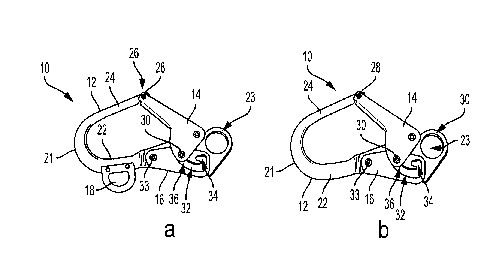
A hand line hook having a curved body portion, a gate pivotally attached to the body, and a gate lock pivotally attached to the body. Detents are formed in the gate lock to further lock the gate in either its open or closed positions.


French Abstract

Un crochet de câble-guide comporte une partie de corps courbée, une porte fixée au corps par pivotement et un verrou de porte fixé par pivotement au corps. Des crans sont formés dans le verrou de porte pour mieux verrouiller la porte dans sa position ouverte ou sa position fermée.

Claims

Note: Claims are shown in the official language in which they were submitted.


WHAT IS CLAIMED IS:
1) A hand line hook, comprising:
a) a hook body comprising a curved nose section positioned between a first end
section and a second end section that terminates in a curved gate detent;
b) a spring-biased, elongated gate pivotally connected at one end to said hook
body
in proximity to a load bearing eye and comprising a rivet that extends
transversely
thereacross and is pivotally movable into and out of engaged relation with
said
curved gate detent, wherein said hook body is closed when said rivet is in
engaged relation with said curved gate detent and is open when not engaged
with
said curved gate detent, said gate further comprising a lock rivet positioned
for
pivotal movement exteriorly of and adjacent to said first end section;
c) a spring-biased gate lock pivotally mounted at a proximal end thereof to
said hook
body in a position exteriorly of and adjacent to said first end section,
comprising
an opening formed therethrough proximate a distal end of said spring-biased
gate
lock and having open lock and closed lock detents formed within said opening,
wherein the opening comprises a curved segment having a first end with the
closed lock detent, a straight segment having a second end with the open lock
detent, and a connecting segment joining the curved segment to the straight
segment, the straight segment extending along a portion of the curved segment
forming a recess between the portion of the curved segment and the straight
segment;
6

d) wherein said lock rivet is forcibly maintained in position due to a spring
bias in
either of said open lock and closed lock detents thereby locking said gate in
either
an open position or a closed position, respectively, relative to said hook
body.
2) The hand line hook according to claim 1, wherein said load bearing eye is
formed as a
part of said hook body at said first end section.
3) the hand line hook according to claim 1 or 2, further comprising a tag line
eye
fixedly attached to said hook body.
7

Description

Note: Descriptions are shown in the official language in which they were submitted.


HAND-LINE HOOK
BACKGROUND
1. FIELD OF INVENTION
[0001] The present invention relates generally to hand line
hooks, and
more particularly to hand line hooks used by utility lineman.
2. BACKGROUND OF ART
[0002] Hand line hooks are used by utility lineman to raise and
lower
tools and equipment from the ground to a lineman working on top of a utility
pole. Most
typically the hand line hook simply comprises a hook and an eye through which
the hand
line can be passed. The tools or equipment are placed over the hook (e.g.,
typically
placed in a bucket with the bucket handle being placed in the hook). By tying
the hand
line through the eye of the hook the workers can then raise and lower the hook
carrying
the tools and equipment. Additional devices, such as pulleys, can be used to
decrease the
amount of force required to raise and lower the load.
[0003] Hand line hooks are not traditionally designed to carry heavier
loads, such as a person in need of rescue. While the hooks strength may be
sufficient, the
open nature of the hook makes such rescue use dangerous. Thus, when a rescue
is
needed, utility workers typically need a different device to assist with
lowering the
worker in need of rescue safely to the ground.
3. OBJECTS AND ADVANTAGES
[0004] It is a principal object and advantage of the present
invention to
provide a gated rated hand line hook that can be used for both traditional
hand line hook
uses and as a rescue device.
1
CA 2972184 2017-06-29

[0005] It is a further object and advantage of the present
invention to
provide a hand line hooks that can be used with a closed gate.
[0006] Other objects and advantages of the present invention
will in part
be obvious and in part appear hereinafter.
SUMMARY OF THE INVENTION
[0007] The present invention comprises a hand line hook of the
type
typically used by utility lineman. An embodiment of the hand line hook is gate
rated and
can be used in conjunction with rated accessories, for lifting heavy loads,
and for rescue
operations. In its preferred embodiment, the hand line hook has a working load
limit of
approximately 2500 lbf when its gate is closed, and 1000 lbf when the gate is
open and in
the intended direction of load.
[0008] In an embodiment, the hand line hook, comprises a hook
body
comprising a curved nose section positioned between a first end section and a
second end
section that terminates in a curved gate detent; a spring-biased, elongated
gate pivotally
connected at one end to the hook body in proximity to a load bearing eye and
comprising
a rivet that extends transversely thereacross and is pivotally movable into
and out of
engaged relation with the curved gate detent, wherein the hook body is closed
when the
rivet is in engaged relation with the curved gate detent and is open when not
engaged
with the curved gate detent, the gate further comprising a lock rivet
positioned for pivotal
movement exteriorly of and adjacent to the first end section; a spring-biased
gate lock
pivotally mounted at a proximal end thereof to the hook body in a position
exteriorly of
and adjacent to the first end section, comprising an opening formed
therethrough
proximate a distal end of the spring-biased gate lock and having open lock and
closed
lock detents formed within the opening, wherein the opening comprises a curved
segment
having a first end with the closed lock detent, a straight segment having a
second end
with the open lock detent, and a connecting segment joining the curved segment
to the
straight segment, the straight segment extending along a portion of the curved
segment
2
CA 2972184 2018-10-09

forming a recess between the portion of the curved segment and the straight
segment;
wherein the lock rivet is forcibly maintained in position due to a spring bias
in either of
the open lock and closed lock detents thereby locking the gate in either an
open position
or a closed position, respectively, relative to the hook body.
[0009] In one embodiment, the hook can further comprise an eye for a tag
line fixedly attached to the hook body adjacent the proximal end of the gate
lock. In
another embodiment, the hook does not include an eye for a tag line. In
another
embodiment, the load bearing eye is formed as a part of the hook body at the
first end
section.
BRIEF DESCRIPTION OF THE DRAWINGS
100101 The present invention will be further understood and
appreciated
by reading the following Detailed Description in conjunction with the
accompanying
drawings, wherein:
100111 Figures 1 a and lb are side elevation views of respective alternate
embodiments of a hand line hook;
[0012] Figure 2 is a side elevation view of a hand line in
accordance with
an embodiment of the present invention.
[0013] Figure 3 is a side elevation view of a tag line eye in
accordance
with an embodiment of the present invention.
[0014] Figure 4 is a side elevation view of a hand line in
accordance with
an embodiment of the present invention with the gate locked closed.
[0015] Figure 5 is a side elevation view of a hand line in
accordance with
an embodiment of the present invention with the gate moved towards it locked
open
position.
[0016] Figure 6 is a side elevation view of a hand line in
accordance with
an embodiment of the present invention with the gate locked open.
3
CA 2972184 2018-10-09

[0017] Figure 7 is a side elevation view of a hand line in
accordance with
an embodiment of the present invention with the gate being moved towards its
locked
closed position.
[0018] Figure 8 is a side elevation view of a hand line in
accordance with
an embodiment of the present invention with the gate in its locked open
position.
DETAILED DESCRIPTION
[0019] Referring now to the drawings, wherein like reference
numerals
refer to like parts throughout, there is seen in Figure 1 a hand line hook,
designated
generally by reference numeral 10, comprising a hook body 12, a spring biased
gate 14
pivotally connected to hook body 12, and a spring biased gate lock 16 also
pivotally
connected to the hook body 12. In one embodiment (Fig. la) hook 10 further
comprises
an eye 18 attached to the hook body 10 adjacent the gate lock 16 that is used
to attach a
tag line, while in another embodiment (Fig. lb) hook 10 does not include the
tag line eye.
[0020] With regard to hook body 12, it comprises a curved nose
section
21 positioned between a first end section 22 that terminates in a load bearing
eye 23 and a
second end section 24 that terminates in a curved gate detent 26 (see Figs. 4 -
8). In one
embodiment (Fig. I a) tag line eye 18 is securely attached by rivets or other
conventional
fasteners to body 12 adjacent first end section 22.
[0021] With regard to gate 14, it is pivotally connected at one
end to hook
body 12 in proximity to the load bearing eye 23 and comprises a rivet 28 that
extends
transversely thereacross and is movable into and out of engaged relation with
the curved
gate detent 26. Hook body 12 is closed when rivet 28 is in engaged relation
with curved
gate detent 26 and is open when not engaged with curved gate detent 26. Gate
14 further
4
CA 2972184 2017-06-29

comprises a lock rivet 30 positioned for pivotal movement exteriorly of and
adjacent to
the body's first end section 22. A conventional spring (leaf, soil, etc.) can
be mounted
within gate 14 to effect it spring bias towards its closed position.
100221 With regard to gate lock 16, it is pivotally mounted (by
rivet 33
about which the pivot occurs) at its proximal end to the hook body 12 in a
position
exteriorly of and adjacent to first end section 22. It comprises an opening 32
formed
therethrough proximate its distal end and has open lock and closed lock
detents 34, 36,
respectively, formed within opening 32, wherein the lock rivet 30 is forcibly
maintained
in position due to its spring bias (coil spring, leaf spring, or other
conventional spring can
be mounted within gate lock 16 and/or around rivet 33 to effect the spring
bias) in either
of the open lock and closed lock detents 34, 36, thereby locking gate 14 in
either its open
or closed positions, respectively, relative to hook body 12.
5
CA 2972184 2018-10-09

Representative Drawing
A single figure which represents the drawing illustrating the invention.
Administrative Status

2024-08-01:As part of the Next Generation Patents (NGP) transition, the Canadian Patents Database (CPD) now contains a more detailed Event History, which replicates the Event Log of our new back-office solution.

Please note that "Inactive:" events refers to events no longer in use in our new back-office solution.

For a clearer understanding of the status of the application/patent presented on this page, the site Disclaimer , as well as the definitions for Patent , Event History , Maintenance Fee  and Payment History  should be consulted.

Event History

Description Date
Inactive: COVID 19 - Deadline extended 2020-06-10
Common Representative Appointed 2019-10-30
Grant by Issuance 2019-04-09
Inactive: Cover page published 2019-04-08
Inactive: Final fee received 2019-02-20
Pre-grant 2019-02-20
Notice of Allowance is Issued 2019-02-05
Letter Sent 2019-02-05
4 2019-02-05
Notice of Allowance is Issued 2019-02-05
Inactive: Approved for allowance (AFA) 2019-01-24
Inactive: Q2 passed 2019-01-24
Amendment Received - Voluntary Amendment 2018-10-09
Inactive: S.30(2) Rules - Examiner requisition 2018-04-11
Inactive: Report - No QC 2018-04-06
Application Published (Open to Public Inspection) 2017-12-29
Inactive: Cover page published 2017-12-28
Inactive: IPC assigned 2017-11-23
Inactive: First IPC assigned 2017-11-23
Inactive: <RFE date> RFE removed 2017-07-11
Inactive: Filing certificate - RFE (bilingual) 2017-07-11
Letter Sent 2017-07-11
Inactive: <RFE date> RFE removed 2017-07-11
Letter Sent 2017-07-10
Application Received - Regular National 2017-07-06
Request for Examination Requirements Determined Compliant 2017-06-29
All Requirements for Examination Determined Compliant 2017-06-29

Abandonment History

There is no abandonment history.

Fee History

Fee Type Anniversary Year Due Date Paid Date
Application fee - standard 2017-06-29
Request for examination - standard 2017-06-29
Registration of a document 2017-06-29
Final fee - standard 2019-02-20
MF (patent, 2nd anniv.) - standard 2019-07-02 2019-06-21
MF (patent, 3rd anniv.) - standard 2020-06-29 2020-06-19
MF (patent, 4th anniv.) - standard 2021-06-29 2021-06-25
MF (patent, 5th anniv.) - standard 2022-06-29 2022-06-24
MF (patent, 6th anniv.) - standard 2023-06-29 2023-06-23
MF (patent, 7th anniv.) - standard 2024-07-02 2024-06-21
Owners on Record

Note: Records showing the ownership history in alphabetical order.

Current Owners on Record
BUCKINGHAM MANUFACTURING CO., INC.
Past Owners on Record
DEFOREST CANFIELD
Past Owners that do not appear in the "Owners on Record" listing will appear in other documentation within the application.
Documents

To view selected files, please enter reCAPTCHA code :


To view images, click a link in the Document Description column (Temporarily unavailable). To download the documents, select one or more checkboxes in the first column and then click the "Download Selected in PDF format (Zip Archive)" or the "Download Selected as Single PDF" button.

List of published and non-published patent-specific documents on the CPD .

If you have any difficulty accessing content, you can call the Client Service Centre at 1-866-997-1936 or send them an e-mail at CIPO Client Service Centre.

({010=All Documents, 020=As Filed, 030=As Open to Public Inspection, 040=At Issuance, 050=Examination, 060=Incoming Correspondence, 070=Miscellaneous, 080=Outgoing Correspondence, 090=Payment})


Document
Description 
Date
(yyyy-mm-dd) 
Number of pages   Size of Image (KB) 
Abstract 2017-06-28 1 6
Description 2017-06-28 5 169
Claims 2017-06-28 1 35
Drawings 2017-06-28 1 32
Representative drawing 2017-11-23 1 9
Description 2018-10-08 5 181
Claims 2018-10-08 2 46
Maintenance fee payment 2024-06-20 46 1,899
Acknowledgement of Request for Examination 2017-07-10 1 173
Filing Certificate 2017-07-10 1 204
Courtesy - Certificate of registration (related document(s)) 2017-07-09 1 103
Commissioner's Notice - Application Found Allowable 2019-02-04 1 161
Reminder of maintenance fee due 2019-03-03 1 110
Amendment / response to report 2018-10-08 11 392
Examiner Requisition 2018-04-10 4 187
Final fee 2019-02-19 1 43