Note: Descriptions are shown in the official language in which they were submitted.
CA 02972972 2017-07-04
1
H8324288CA
Scanning body system for determining a positioning and orientation of a dental
implant
The invention relates to a scanning body system for determining a positioning
and orientation
of a dental implant, with a base part comprising an interface, and with a
scanning part which
has a three-dimensional scanning contour and is firmly connected to the base
part to form a
scanning body, and with a fastening screw which is provided for fastening the
scanning body
in the dental implant.
Such a scanning body system is disclosed in DE 20 2013 005 821 U1. The known
scanning
body system includes a scanning body comprising a base part and a scanning
part which are
produced as separate components made of different materials and subsequently
com-
pressed to obtain the scanning body. Prior to joining the base part and the
scanning part, a
fastening screw is inserted into a locating channel of the base part, which
screw is captively
held in the scanning body after force-fitted joining of the base part and the
scanning part. The
scanning part includes, on the top side facing away from the base part, a
passage towards
an interior of the scanning part, wherein the fastening screw is positioned.
The passage is to
allow passing of a tool in order to turn the fastening screw. A cross section
of the passage is
smaller than a passage of a screw head of the fastening screw so that the
fastening screw is
captively held in the scanning body after joining of the base part and the
scanning part.
An object of the invention is to provide a scanning body system of the type
mentioned in the
introduction, which has improved functional options as compared to the prior
art.
This object is achieved in that the base part and/or the fastening screw
are/is provided with
at least one mechanical retaining means which holds the fastening screw, after
inserting
through a passage of the scanning part into the scanning body, captively
within the scanning
body. The scanning body system according to the invention allows separate
storage and
handling of scanning body and fastening screw. Nevertheless, after inserting
into the scan-
ning body, the fastening screw is held captively within the scanning body so
that inadvertent
loss of the fastening screw, in particular during intraoral application of the
scanning body sys-
tem, is prevented.
In an embodiment of the invention, the retaining means are designed such that
the fastening
screw, after inserting into the scanning body, can be removed from the
scanning body later
on. As compared to the prior art, this feature allows improved cleaning
capability of the scan-
ning body system. Namely, the possible removal of the fastening screw from the
scanning
body offers an improved feasibility of cleaning the interior of the scanning
body. As a result,
the scanning body system allows a particularly hygienic multiple usage.
In a further embodiment of the invention, the passage of the scanning part is
provided on an
end side facing away from the base part, and a cross section of the passage is
equal to or
greater than a greatest cross section of the fastening screw. Thereby, it is
ensured that the
CA 02972972 2017-07-04
2
H8324288CA
fastening screw can be inserted from the exterior through the passage of the
scanning part
into the interior of the scanning body.
In a further embodiment of the invention, the mechanical retaining means is
provided on an
outer circumference of the fastening screw or on an inner circumference of a
locating chan-
nel of the base part surrounding the fastening screw. The mechanical retaining
means pref-
erably gives force-fitting or form-fitting support for the fastening screw.
Across and through
the scanning part of the scanning body, the fastening screw can both be
inserted from the
exterior and, after inserting, again be removed towards the exterior.
In a further embodiment of the invention, the mechanical retaining means is
integrally molded
to the inner circumference of the locating channel. With particular advantage,
the retaining
means is an internal thread section on the inner circumference of the locating
channel com-
plementary to an external thread of the fastening screw. The integral molding,
in particular
the configuration of an internal thread section, is feasible in a simple and
cost-efficient man-
ner.
In a further embodiment of the invention, the retaining means is embodied in
an elastically
resilient annular portion protruding radially outwards beyond an outer contour
of the fastening
screw. The elastically resilient annular portion can be disposed on the
fastening screw in
material-bonding engagement, in particular by vulcanizing or adhesively
bonding. As an al-
ternative, the elastically resilient annular portion can be designed by at
least one separately
manufactured elastic annular structure connected to the outer contour of the
fastening screw
in a force-fitting or form-fitting manner.
In a further embodiment of the invention, the annular portion includes an 0-
ring made of an
elastomer material, which ring is held in an annular groove of the fastening
screw. Advanta-
geously, the annular groove is provided on a screw head of the fastening
screw. The annular
groove can be worked in the screw head of the fastening screw by machining.
The elastically
resilient 0-ring can, subsequently, be elastically enlarged and inserted into
the annular
groove by simple ways and means. What is meant by elastomer material are as
well materi-
als made of synthetic or natural rubber and also materials made of
thermoplastic elastomers.
Further advantages and features of the invention will become apparent from the
claims and
from the description below of preferred exemplary embodiments of the invention
which are
illustrated with reference to the drawings.
Fig. 1 shows a sectional view of a first embodiment of a scanning body system
according to
the invention; and
Fig. 2 shows, likewise in a sectional view, another embodiment of a scanning
body system
according to the invention.
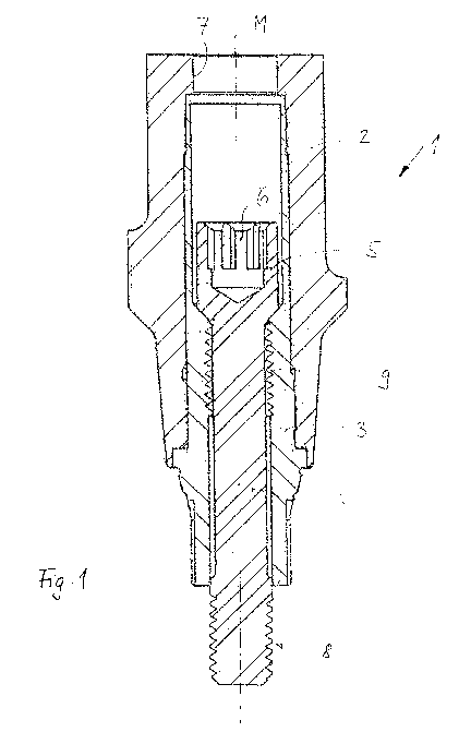
Both scanning body systems 1 and 1a according to Figs. 1 and 2 exhibit
principally the same
structural design. Thus, parts or portions of the scanning body systems 1, la
of similar func-
CA 02972972 2017-07-04
3
H8324288CA
tionality are provided with the same reference numerals, however, in relation
to the embodi-
ment according to Fig. 2 with the letter "a" added. Both the scanning body
systems 1, 1a
each include a scanning body composed of a scanning part 2 and a base part 3.
Each base
part 3, 3a is made of a metallic material, preferably a titanium alloy. Each
scanning part 2 is
molded of a synthetic material, in the present case made of PEEK, and has in
the region of
its outer contour a plurality of scanning surfaces of different design, which
are arranged dis-
tributed over a circumference of the scanning part 2 and define a three-
dimensional scanning
contour. The scanning part 2, 2a and the base part 3, 3a are firmly connected
to each other
by coaxial joining lengthwise a central longitudinal axis M. Joining is in a
force-fitting manner
by pressing the base part 3, 3a into the scanning part 2. For that purpose,
the scanning part
2, 2a is provided with a seat that is open towards opposite end sides, which
seat leads, on a
side remote from the base part 3, 3a, into a passage 7, 7a that will be
described in more de-
tail below. Mutually facing contact surfaces of the base part 3, 3a on the one
hand and the
scanning part 2, 2a on the other hand can additionally be provided with
latching profilings, in
order to further improve cohesion between scanning part 2, 2a and base part 3,
3a after
compression.
Owing to the joining of the scanning part 2, 2a to the base part 3, 3a, a
scanning body to be
handled as one structural unit is obtained, which scanning body is capable of
being inserted
into a dental implant (not illustrated) and capable of being positioned within
the dental im-
plant in a non-rotating manner by means of an interface (not illustrated in
more detail) on a
section of the base part 3, 3a protruding beyond the scanning part 2, 2a
opposite to the pas-
sage 7, 7a. The interface on the, in relation to the scanning part 2, 2a,
lower end section of
the base part 3, 3a is provided with rotationally asymmetric profilings on the
outer circumfer-
ence thereof, which are matched to complementary inner profilings of the
dental implant.
Moreover, the scanning body system 1, la includes a fastening screw 4, 4a
which is provid-
ed with a screw head 5, 5a on an upper face end region and with an external
thread 8, 8a on
an opposite face end region. The external thread 8, 8a has a configuration
complementary to
an internal thread of the dental implant, in order to allow screwing in and
out of the fastening
screw 4, 4a relative to the dental implant.
The screw head 5, 5a of the fastening screw 4, 4a has a cylindrical design and
a diameter
which is greater than a cylindrical screw shaft of the respective fastening
screw 4, 4a, with
the external thread 8, 8a provided on the lower face end region thereof.
However, the diame-
ter of the screw head 5, 5a of the fastening screw 4, 4a is smaller than or
equal to a diameter
of the passage 7, 7a on the upper face end region of the scanning part 2, 2a.
This feature
allows that the fastening screw 4, 4a can be stored and handled separate from
the scanning
body 2, 3; 2a, 3a. The fastening screw 4, 4a is driven through the passage 7,
7a of the scan-
ning part 2, 2a from above coaxially in relation to the central longitudinal
axis M of the scan-
ning body 2, 3; 2a, 3a for a ready-for-use assembly of the scanning body
system 1, la.
In the embodiment according to Fig. 1, an internal thread section 9 is
provided on an inner
circumference of a locating channel of the base part 3 extending within the
scanning part 2
CA 02972972 2017-07-04
4
H8324288CA
on an upper section remote from the interface, which thread section serves as
mechanical
retaining means for securing the fastening screw 4 in the scanning body 2, 3.
The internal
thread section 9 has a configuration complementary to the external thread 8 of
the fastening
screw 4. After inserting the fastening screw 4 from above across and through
the passage 7,
the external thread 8 meets the internal thread section 9 of the base part 3.
By means of
simple screwing in of the fastening screw 4 using a tool engaging the tool
engagement sur-
faces 6, the fastening screw 4 can be screwed through the internal thread
section 9. The
internal thread section 9 extends merely over approximately one third of the
axial length of
the locating channel of the base part 3 (not illustrated in more detail) so
that the fastening
screw 4, after screwing the external thread 8 through the internal thread
section 9, is again
axially movable. However, the internal thread section 9 prevents that the
fastening screw 4
can be pushed back out of the passage 7 axially upwards. Indeed, removing of
the fastening
screw 4 is possible merely in that the fastening screw 4 is initially pushed
back axially up-
wards, until the external thread 8 abuts on a lower edge of the internal
thread section 9. Sub-
sequently, the screw has to be screwed out axially upwards via said internal
thread section 9,
before it comes clear and can be withdrawn completely to the outside.
In the embodiment according to Fig. 2, the base part 3a does not have an
internal thread
section within its locating channel. Rather, the locating channel has a
cylindrical design so
that the fastening screw 4a and its screw shaft can be shifted axially within
said locating
channel. The mechanical retaining means of the fastening screw 4a is created
by a radially
elastically resilient 0-ring 9a which is held in an annular groove 10
integrally molded in the
screw head 5a. A depth of the annular groove 10 is embodied such that the 0-
ring can be
pressed in elastically far enough that it does no longer protrude beyond an
outer contour of
the screw head 5a of the fastening screw. The elastic pre-tensioning of the 0-
ring 9a is such
that the 0-ring 9a is always urged radially outwards and, thus, allows force-
fitting support of
the fastening screw 4a in the base part 3a and in the scanning part 2a.
Since the diameter of the screw head 5a is smaller than or equal to the
passage 7a of the
scanning part 2a, the fastening screw 4a can be pushed in axially from above
into the scan-
ning body 2a, 3a. Once the 0-ring 9a, which is retained in the annular groove
10, comes to
abut on an upper face end edge of the passage 7a and, owing to the elastic
resilience of the
0-ring, the ring is urged inwards into the annular groove 10, whereby the
fastening screw 4a
can slide further downwards. The radially outwards acting elastic tension of
the 0-ring 9a is
sufficient in order to retain the fastening screw 4a in the scanning body 2a,
3a. Moreover, a
radially outwards enlarged annular step is provided between the passage 7a and
the adja-
cent seat of the scanning part 2a for the base part 3a such that, during an
axial shifting of the
fastening screw 4a, the 0-ring 9a is additionally supported towards the top on
said annular
step in a form-fitting manner. However, in the case as illustrated in Fig. 2,
with the fastening
screw 4a in an inserted condition, if an axial force acts from below, i.e.
from an end side fac-
ing the external thread 8a, upwards onto the fastening screw 4a, the 0-ring 9a
is again elas-
tically and radially urged back inwards in the region of the annular shoulder
and can slide
upwards through the passage 7a, whereby the fastening screw 4a can be axially
withdrawn
from the seat in the scanning body 2a, 3a. Said withdrawal, i.e. removal of
the fastening
CA 02972972 2017-07-04
H8324288CA
screw 4, 4a, allows a particularly facilitated and hygienic cleaning of the
interior of the re-
maining scanning body 2, 3; 2a, 3a with both scanning body systems 1, la.
Moreover, even
the fastening screw 4, 4a as such can be cleaned by simple ways and means,
while it is de-
tached from the scanning body 2, 3; 2a, 3a.