Language selection

Search

Patent 2973359 Summary

Third-party information liability

Some of the information on this Web page has been provided by external sources. The Government of Canada is not responsible for the accuracy, reliability or currency of the information supplied by external sources. Users wishing to rely upon this information should consult directly with the source of the information. Content provided by external sources is not subject to official languages, privacy and accessibility requirements.

Claims and Abstract availability

Any discrepancies in the text and image of the Claims and Abstract are due to differing posting times. Text of the Claims and Abstract are posted:

  • At the time the application is open to public inspection;
  • At the time of issue of the patent (grant).
(12) Patent: (11) CA 2973359
(54) English Title: DOOR POSITION DETECTION DEVICE FOR ELECTRIC DOOR OPENER
(54) French Title: DISPOSITIF DE DETECTION DE POSITION DE PORTE DESTINE A UN OUVRE-PORTE ELECTRIQUE
Status: Granted and Issued
Bibliographic Data
(51) International Patent Classification (IPC):
  • E05F 15/60 (2015.01)
(72) Inventors :
  • JIAN, MINGSHAO (China)
(73) Owners :
  • FORESEE GARAGE DOORS CO., LTD.
(71) Applicants :
  • FORESEE GARAGE DOORS CO., LTD. (China)
(74) Agent: NELLIGAN O'BRIEN PAYNE LLP
(74) Associate agent:
(45) Issued: 2019-04-30
(22) Filed Date: 2017-07-14
(41) Open to Public Inspection: 2018-07-22
Examination requested: 2017-07-14
Availability of licence: N/A
Dedicated to the Public: N/A
(25) Language of filing: English

Patent Cooperation Treaty (PCT): No

(30) Application Priority Data:
Application No. Country/Territory Date
201720091493.3 (China) 2017-01-22

Abstracts

English Abstract

The invention relates to a door position detection device for an electric door opener, comprising a housing, in which an input gear in connection with a driving device is mounted and an output gear is further mounted; the input gear and the output gear are linked through a reduction gear unit, a magnet is fixed on the output gear, a magnetic angle sensor circuit board is fixed on the housing above the magnet, and a magnetic angle sensor chip perpendicularly corresponding to the magnet is arranged on the magnetic angle sensor circuit board; the door position detection device is simple and reasonable in structure, has long service life and high precision and can detect any position immediately.


French Abstract

Linvention concerne un dispositif de détection de position de porte destiné à un ouvre-porte électrique. Linvention comprend un boîtier, dans lequel un engrenage dentrée raccordé à un dispositif dentraînement est fixé et un engrenage de sortie est également fixé. Les engrenages dentrée et de sortie sont reliés par une unité de démultiplicateur, un aimant est fixé à lengrenage de sortie, une carte de circuits imprimés à capteur dangle magnétique est fixée au boîtier au-dessus de laimant et une puce de capteur dangle magnétique correspondant perpendiculairement à laimant est disposée sur la carte de circuits imprimés à capteur dangle magnétique. Le dispositif de détection de position de porte présente une structure simple et raisonnable, a une longue durée de vie utile, est très précis et peut détecter immédiatement toute position.

Claims

Note: Claims are shown in the official language in which they were submitted.

Claims
1. A door position detection device for an electric door opener, comprising:
a housing, in which an input gear in connection with a driving device is
mounted,
characterized in that:
an output gear is further mounted in the housing, the input gear and the
output gear are
linked through a reduction gear unit, a magnet is fixed on the output gear,
a magnetic angle sensor circuit board is fixed on the housing above the
magnet, and a
magnetic angle sensor chip perpendicularly corresponding to the magnet is
arranged on the
magnetic angle sensor circuit board;
characterized in that: a fixing bracket is arranged above the magnet, a
connection lug is
extended on the edge of the fixing bracket, a connection post mated with the
connection lug is
arranged on the corresponding housing, and the magnetic angle sensor circuit
board is fixed on
the fixing bracket; and
characterized in that: a recessed cavity suitable for accommodating and fixing
the magnet is
arranged on the output gear.
2. The door position detection device for an electric door opener according to
claim 1,
characterized in that: the reduction gear unit comprises a first reduction
gear and a second
reduction gear that are engaged with each other, the first reduction gear is
engaged with the
input gear, and the second reduction gear is engaged with the output gear.
3. The door position detection device for an electric door opener according to
claim 1,
characterized in that: the magnetic angle sensor circuit board is provided
with an electrical
connection port.
4. The door position detection device for an electric door opener according to
claim 1,
characterized in that: a range of the rotation of the output gear is less than
360 degrees.
5. A door position detection device for an electric door opener, comprising:
a. a housing,
b. an input gear in connection with a driving device, mounted in the housing,
c. an output gear, further mounted in the housing, wherein the input gear and
the output
gear are linked through a reduction gear unit,
d. a magnet, fixed to the housing,
6

e. a magnetic angle sensor circuit board is fixed on the output gear, the
magnet angle
sensor circuit comprising a magnetic angle sensor chip for detecting an angle
from the
magnet;
wherein the housing further comprising a fixing bracket being arranged over
the magnetic angle
sensor circuit, a connection lug is extended on the edge of the fixing
bracket, a connection post
mated with the connection lug is arranged on the corresponding housing, and
the magnet is
fixed on the fixing bracket; and
wherein the output gear defines a recessed cavity for accommodating and fixing
the magnetic
angle sensor circuit board.
7

Description

Note: Descriptions are shown in the official language in which they were submitted.


File No. 34994-2
DOOR POSITION DETECTION DEVICE FOR ELECTRIC DOOR
OPENER
TECHNICAL FIELD
[0001] The invention relates to the technical field of electric door openers,
and in particular to
a door position detection device for an electric door opener.
BACKGROUD
[0002] At present, door position detection devices for electric door openers
have following
1 0 schemes:
[0003] 1. Adopting a photoelectric encoder, whose defects lie in that the
precision is not high
enough and a current position can be calculated only when the door moves for
certain distance.
[0004] 2. Adopting an absolute-value photoelectric encoder, whose defect lies
in high cost.
[0005] 3. Adopting an incremental photoelectric encoder, whose defects lie in
that the door
position is lost after the door is manually opened when the door opener is
powered off, and
devices such as limit switch are needed to regain the door position.
[0006] 4. Adopting a potentiometer, whose defects lie in short service life
and low precision.
[0007] 5. Adopting a limit switch, whose defects lie in that only the fully
open or fully closed
position of the door can be known, the door cannot be detected at any
intermediate position, and
more complex functions cannot be realized, for example, slow start and slow
stop, or partial
opening, positional opening, etc.
SUMMARY
[0008] The invention aims to solve the above defects in existing technologies
and provide a
door position detection device for an electric door opener, which is simple
and reasonable in
structure, has long service life and high precision and can detect any
position immediately; if a
door is pulled randomly after the door opener is powered off, the door
position detection device
can know the requirement of door position detection immediately once the door
opener is
powered on; therefore, the problem of door position change of door openers is
thoroughly
solved, higher-precision door position control is realized and the electric
door opener is more
diversified and safer in function.
[0009] The technical scheme adopted by the invention to solve the technical
problem is as
CA 2973359 2017-07-14

File No. 34994-2
follows.
[0010] A door position detection device for an electric door opener includes a
housing, in
which an input gear in connection with a driving device is mounted,
characterized in that: an
output gear is further mounted in the housing, the input gear and the output
gear are linked
through a reduction gear unit, a magnet is fixed on the output gear, a
magnetic angle sensor
circuit board is fixed on the housing above the magnet, and a magnetic angle
sensor chip
perpendicularly corresponding to the magnet is arranged on the magnetic angle
sensor circuit
board.
[0011] The door position detection device for an electric door opener adopting
this structure
realizes position detection through the magnet and the magnetic angle sensor
chip on the
magnetic angle sensor circuit board, that is, the magnet rotates following the
output gear,
however, the magnetic angle sensor chip above the magnet is immovable, in this
way, when the
door is at any position within the travel, a unique angle exists between the
magnetic field of the
radially arranged magnet and the magnetic angle sensor chip, and the detection
of the magnetic
field angle through the magnetic angle sensor chip may acquire a high-
precision (the precision
may reach 12 bits, even 14 bits) position signal.
[0012] Moreover, even if a door is pulled randomly after the door opener is
powered off, the
door position detection device can know the requirement of door position
detection immediately
once the door opener is powered on; therefore, the problem of door position
change of door
openers is thoroughly solved, higher-precision door position control is
realized and the electric
door opener is more useful and safer and has longer service life.
[0013] The invention may also adopt the following technical means to solve the
above
problem.
[0014] As a preferred scheme, the reduction gear unit includes a first
reduction gear and a
second reduction gear that are engaged with each other, the first reduction
gear is engaged with
the input gear, and the second reduction gear is engaged with the output gear;
the reduction gear
unit may be combined according to different gear ratios.
[0015] As a preferred scheme, a fixing bracket is arranged above the magnet, a
connection lug
is extended on the edge of the fixing bracket, a connection post mated with
the connection lug is
arranged on the corresponding housing, and the magnetic angle sensor circuit
board is fixed on
the fixing bracket; the purpose of the fixing bracket is to fix the magnetic
angle sensor circuit
board, a plurality of connection lugs and a plurality of connection posts are
correspondingly
mated and are connected through fasteners, with simple and reasonable
structure.
2
CA 2973359 2017-07-14

.
File No. 34994-2
,
,
[0016] As a preferred scheme, the magnetic angle sensor circuit board is
provided with an
electrical connection port, for the convenience of wiring and signal
transmission.
[0017] As a preferred scheme, a recessed cavity suitable for accommodating and
fixing the
magnet is arranged on the output gear, for the convenience of fixing the
magnet.
[0018] As a preferred scheme, during the working process, the rotation of the
output gear is
less than 360 degrees, thereby making the computation program simple and being
capable of
acquiring the unique angle information about the door position in each
condition.
[0019] As a preferred scheme, the mounting positions of the magnet and the
magnetic angle
sensor circuit board are exchanged each other; since the magnet and the
magnetic angle sensor
chip are in relative motion, supposing the magnetic angle sensor circuit board
is fixed on the
output gear and the magnet is fixed on the fixing bracket, the same purpose
also can be
achieved.
[0020] The invention has benefits as follows.
[0021] The door position detection device for an electric door opener in the
invention realizes
contactless detection, prolongs the service life and realizes immediate
detection; if a door is
pulled randomly after the door opener is powered off, the door position
detection device can
know the requirement of door position detection immediately once the door
opener is powered
on; therefore, the problem of door position change of door openers is
thoroughly solved,
higher-precision door position control is realized and the electric door
opener is more useful and
safer.
BRIEF DESCRIPTION OF THE DRAWINGS
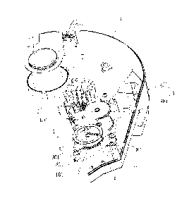
[0022] FIG 1 is a structure diagram of the invention.
DESCRIPTION OF THE EMBODIMENTS
[0023] The invention is described below in further detail in conjunction with
accompanying
drawings and embodiments.
[0024] As shown in FIG 1, a door position detection device for an electric
door opener
includes a housing 1, in which an input gear 2 in connection with a driving
device is mounted,
characterized in that: an output gear 3 is further mounted in the housing 1,
the input gear 2 and
the output gear 3 are linked through a reduction gear unit 4, a magnet 5 is
fixed on the output
gear 3, a magnetic angle sensor circuit board 6 is fixed on the housing 1
above the magnet 5,
and a magnetic angle sensor chip 7 perpendicularly corresponding to the magnet
5 is arranged
3
CA 2973359 2017-07-14

.
File No. 34994-2
on the magnetic angle sensor circuit board 6.
[0025] The door position detection device for an electric door opener adopting
this structure
realizes position detection through the magnet 5 and the magnetic angle sensor
chip 7 on the
magnetic angle sensor circuit board 6, that is, the magnet 5 rotates following
the output gear 3,
however, the magnetic angle sensor chip 7 above the magnet 5 is immovable, in
this way, when
the door is at any position within the travel, a unique angle exists between
the magnetic field of
the radially arranged magnet 5 and the magnetic angle sensor chip 7, and the
detection of the
magnetic field angle through the magnetic angle sensor chip 7 may acquire a
high-precision (the
precision may reach 12 bits, even 14 bits) position signal.
[0026] Moreover, even if a door is pulled randomly after the door opener is
powered off, the
door position detection device can know the requirement of door position
detection immediately
once the door opener is powered on; therefore, the problem of door position
change of door
openers is thoroughly solved, higher-precision door position control is
realized and the electric
door opener is more useful and safer and has longer service life.
[0027] The reduction gear unit 4 includes a first reduction gear 401 and a
second reduction
gear 402 that are engaged with each other, the first reduction gear 401 is
engaged with the input
gear 2, and the second reduction gear 402 is engaged with the output gear 3;
the reduction gear
unit 4 may be combined according to different gear ratios.
[0028] A fixing bracket 8 is arranged above the magnet 5, a connection lug 801
is extended
on the edge of the fixing bracket 8, a connection post 101 mated with the
connection lug 801 is
arranged on the corresponding housing 1, and the magnetic angle sensor circuit
board 6 is fixed
on the fixing bracket 8; the purpose of the fixing bracket 8 is to fix the
magnetic angle sensor
circuit board 6, a plurality of connection lugs 801 and a plurality of
connection posts 101 are
correspondingly mated and are connected through fasteners, with simple and
reasonable
structure.
[0029] The magnetic angle sensor circuit board 6 is provided with an
electrical connection
port 601, for the convenience of wiring and signal transmission.
[0030] A recessed cavity 301 suitable for accommodating and fixing the magnet
5 is arranged
on the output gear 3, for the convenience of fixing the magnet 5.
[0031] During the working process, the rotation of the output gear 3 is less
than 360 degrees,
thereby making the computation program simple and being capable of acquiring
the unique
angle information about the door position in each condition.
[0032] As a further embodiment, the mounting positions of the magnet 5 and the
magnetic
4
CA 2973359 2017-07-14

File No. 34994-2
angle sensor circuit board 6 are exchanged; since the magnet 5 and the
magnetic angle sensor
chip 7 are in relative motion, supposing the magnetic angle sensor circuit
board 6 is fixed on the
output gear and the magnet 5 is fixed on the fixing bracket 8, the same
purpose also can be
achieved.
[0033] The above specific embodiments are merely preferred embodiments of the
invention;
all equivalent designs made according to the scope of the patent applied by
the invention are
intended to be covered by the technology of the invention.
5
CA 2973359 2017-07-14

Representative Drawing
A single figure which represents the drawing illustrating the invention.
Administrative Status

2024-08-01:As part of the Next Generation Patents (NGP) transition, the Canadian Patents Database (CPD) now contains a more detailed Event History, which replicates the Event Log of our new back-office solution.

Please note that "Inactive:" events refers to events no longer in use in our new back-office solution.

For a clearer understanding of the status of the application/patent presented on this page, the site Disclaimer , as well as the definitions for Patent , Event History , Maintenance Fee  and Payment History  should be consulted.

Event History

Description Date
Inactive: Office letter 2024-03-28
Change of Address or Method of Correspondence Request Received 2020-05-07
Common Representative Appointed 2019-10-30
Grant by Issuance 2019-04-30
Inactive: Cover page published 2019-04-29
Pre-grant 2019-03-20
Inactive: Final fee received 2019-03-20
Notice of Allowance is Issued 2019-01-15
Letter Sent 2019-01-15
Notice of Allowance is Issued 2019-01-15
Inactive: Approved for allowance (AFA) 2019-01-07
Inactive: QS passed 2019-01-07
Amendment Received - Voluntary Amendment 2018-12-03
Inactive: S.30(2) Rules - Examiner requisition 2018-07-26
Inactive: Report - No QC 2018-07-23
Inactive: Cover page published 2018-07-22
Application Published (Open to Public Inspection) 2018-07-22
Inactive: IPC assigned 2017-10-10
Inactive: First IPC assigned 2017-10-10
Filing Requirements Determined Compliant 2017-07-20
Inactive: Filing certificate - RFE (bilingual) 2017-07-20
Letter Sent 2017-07-19
Application Received - Regular National 2017-07-18
All Requirements for Examination Determined Compliant 2017-07-14
Request for Examination Requirements Determined Compliant 2017-07-14
Small Entity Declaration Determined Compliant 2017-07-14

Abandonment History

There is no abandonment history.

Fee History

Fee Type Anniversary Year Due Date Paid Date
Application fee - small 2017-07-14
Request for examination - small 2017-07-14
Final fee - small 2019-03-20
MF (patent, 2nd anniv.) - small 2019-07-15 2019-06-27
MF (patent, 3rd anniv.) - small 2020-07-14 2020-06-24
MF (patent, 4th anniv.) - small 2021-07-14 2021-05-26
MF (patent, 5th anniv.) - small 2022-07-14 2022-06-20
MF (patent, 6th anniv.) - small 2023-07-14 2023-06-19
MF (patent, 7th anniv.) - small 2024-07-15 2024-06-27
Owners on Record

Note: Records showing the ownership history in alphabetical order.

Current Owners on Record
FORESEE GARAGE DOORS CO., LTD.
Past Owners on Record
MINGSHAO JIAN
Past Owners that do not appear in the "Owners on Record" listing will appear in other documentation within the application.
Documents

To view selected files, please enter reCAPTCHA code :


To view images, click a link in the Document Description column. To download the documents, select one or more checkboxes in the first column and then click the "Download Selected in PDF format (Zip Archive)" or the "Download Selected as Single PDF" button.

List of published and non-published patent-specific documents on the CPD .

If you have any difficulty accessing content, you can call the Client Service Centre at 1-866-997-1936 or send them an e-mail at CIPO Client Service Centre.


Document
Description 
Date
(yyyy-mm-dd) 
Number of pages   Size of Image (KB) 
Description 2017-07-14 5 246
Claims 2017-07-14 1 49
Abstract 2017-07-14 1 17
Drawings 2017-07-14 1 60
Representative drawing 2018-06-18 1 24
Cover Page 2018-06-18 2 61
Claims 2018-12-03 2 65
Cover Page 2019-04-02 2 66
Maintenance fee payment 2024-06-27 2 48
Courtesy - Office Letter 2024-03-28 2 188
Acknowledgement of Request for Examination 2017-07-19 1 174
Filing Certificate 2017-07-20 1 204
Commissioner's Notice - Application Found Allowable 2019-01-15 1 163
Reminder of maintenance fee due 2019-03-18 1 110
Examiner Requisition 2018-07-26 3 196
Amendment / response to report 2018-12-03 6 203
Final fee 2019-03-20 1 38
Maintenance fee payment 2020-06-24 1 26
Maintenance fee payment 2021-05-26 1 26