Note: Descriptions are shown in the official language in which they were submitted.
CA 02974336 2017-07-19
WO 2016/118236 PCT/US2015/062995
ECG ELECTRODE SNAP CONNECTOR AND ASSOCIATED METHODS
Related Applications
[0001] This application claims the benefit under 35 U.S.C. 119(e) of U.S.
Non-
Provisional Patent Application Serial No. 14/600,939 filed by the inventor of
the present
application on January 20, 2015, and titled ECG Electrode Snap Connector and
Associated Methods, the entire content of which is incorporated herein by
reference
except to the extent that disclosure therein is inconsistent with disclosure
herein.
Field of the Invention
[0002] The present invention relates to systems and methods for
simultaneously
tracking ECG (electrocardiogram) data and movement/acceleration data using a
common sensor housing.
Background
[0003] In conventional ECG signal measurement, disposable adhesive
electrode
patches are affixed to the surface of the skin and electrocardiograph lead
wires are
attached to these electrodes. There are many ways of attaching the lead wires
to these
electrodes with the most common being the use of parallel spring snaps.
[0004] While taking ECG signal measurements, stray signals, which do not
relate
to the heart signal, that is artifacts, can occur. One of the major causes of
artifacts is
the movement of the patient's body during the signal measurements, which can
produce
an electrical signal not related to the heart's electrical signal. The
occurrence of
artifacts can lead to incorrect ECG data and can be difficult and time
consuming to
identify and remove from a set of data.
[0005] While certain aspects of conventional technologies have been
discussed
to facilitate disclosure of the invention, the applicant in no way disclaims
these technical
aspects, and it is contemplated that the claimed invention may encompass one
or more
of the conventional technical aspects discussed herein. The present invention
may
1
CA 02974336 2017-07-19
WO 2016/118236 PCT/US2015/062995
address one or more of the problems and deficiencies of the current
availability and
prior art discussed above. However, it is contemplated that the invention may
prove
useful in addressing other problems and deficiencies in a number of technical
areas.
Therefore, the claimed invention should not necessarily be construed as
limited to
addressing any of the particular problems or deficiencies discussed herein, or
limited to
the particular embodiment for the invention used to illustrate the steps and
functionality
of the herein.
[0006] This background information is provided to reveal information
believed by
the applicant to be of possible relevance to the present invention. No
admission is
necessarily intended, nor should be construed, that any of the preceding
information
constitutes prior art against the present invention. This reference or
discussion is not an
admission that the document, act or item of knowledge or any combination
thereof was
at the priority date, publicly available, known to the public, part of common
general
knowledge, or otherwise constitutes prior art under the applicable statutory
provisions;
or is known to be relevant to an attempt to solve any problem with which this
specification is concerned.
Summary of the Invention
[0007] With the above in mind, embodiments of the present invention are
related
to collecting motion data, which corresponds to a location at which an ECG
reading is
taken. This may advantageously allow enhanced diagnosis and a reduction in
artifacts.
[0008] These and other objects, features and advantages according to the
present invention are provided by a connector that includes a housing, a
female snap
connector member carried by the housing and configured to mechanically and
electrically connect to a male snap connector member of an electrode, a three-
axis
accelerometer carried by the housing and configured to sense proper
acceleration of
the connector, and a microprocessor in electrical communication with the snap
connector and with the accelerometer. The microprocessor may be configured to
receive cardiac activity data from the electrode, to receive proper
acceleration data from
the accelerometer, and to correlate the cardiac activity data to the proper
acceleration
data to define processed data.
[0009] The connector may further include a computer readable non-transitory
storage medium carried by the housing. The microprocessor may be configured to
store the cardiac activity data, the proper acceleration data, and/or the
processed data
to the storage medium.
2
CA 02974336 2017-07-19
WO 2016/118236 PCT/US2015/062995
[0010] The connector may also include a lead wire that may be at least
partially
carried by the housing and in data communication with the microprocessor and
with a
computing system. The lead wire may be configured to electronically convey the
cardiac activity data, proper acceleration data, and/or the processed data to
the
computing system.
[0011] The connector may also include a wireless transmitter in data
communication with the microprocessor. The wireless transmitter may be
configured to
wirelessly transmit at least one of the cardiac activity data, proper
acceleration data,
and the processed data to a wireless receiver. The wireless receiver may also
be
configured to electronically convey the cardiac activity data, proper
acceleration data,
and/or the processed data to a computing system.
[0012] The connector may also include an amplifier and an analog-to-digital
converter. The snap connector may be configured to pass the cardiac activity
data in
analog format to the amplifier. The amplifier may be configured to pass the
cardiac
activity data in amplified form to the analog-to-digital converter. Similarly,
the analog-to-
digital converter may be configured to pass the cardiac activity data in
digital format to
the microprocessor. The accelerometer may be configured to pass the proper
acceleration data in digital format to the microprocessor and may be of a
capacitive
type. Further, the electrode may be an Association for the Advancement of
Medical
Instrumentation (AAMI) and/or an American National Standards Institute (ANSI)
standard disposable ECG electrode.
[0013] Another aspect of the invention relates to a retrofit heart rate
monitoring
system and may include a computing system and a connector as described above.
The
cardiac activity data, proper acceleration data, and/or the processed data may
be
transmitted by the monitoring device to the computing system. The
accelerometer of
the connector may be configured to pass the proper acceleration data in
digital format to
the microprocessor. The computing system may be configured to determine
whether
the connector is detached from the electrode using the proper acceleration
data and the
processed data. The computing system may be configured to reduce movement
artifacts using the processed data and may also be configured to detect
respiratory
distress, sleep disturbance, and/or cardiovascular morbidity using the
processed data.
[0014] Another aspect of the invention relates to a method of retrofitting
an ECG
monitoring system using a connector including a female snap connector member,
a
three-axis accelerometer, and a microprocessor in electrical communication
with the
snap connector and with the accelerometer. The method may include mechanically
and
3
CA 02974336 2017-07-19
WO 2016/118236 PCT/US2015/062995
electrically connecting the female snap connector member of the connector to a
male
snap connector member of an electrode. The method may also include detecting
cardiac activity of a patient using the electrode. The method may further
include
detecting proper acceleration of the connector using the accelerometer. The
method
may still further include transmitting cardiac activity data to the
microprocessor from the
electrode and transmitting proper acceleration data to the microprocessor from
the
accelerometer. The method may also include correlating, using the
microprocessor, the
cardiac activity data and the proper acceleration data to define processed
data.
Brief Description of the Drawings
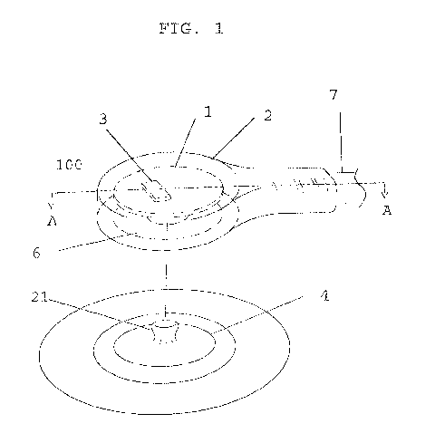
[0015] FIG. 1 is a perspective view of an ECG electrode snap connector
having
portions cut away according to embodiment of the present invention.
[0016] FIG. 2 is a cross sectional view of the ECG electrode snap
connector
illustrated in FIG. 1 and taken through line A--A in FIG. 1.
[0017] FIG. 3 is top view of the ECG electrode snap connector illustrated
in FIG.
1 showing components carried by a housing of the ECG electrode snap connector.
[0018] FIG. 4 is a perspective view of a circuit board carried by the
housing of the
ECG electrode snap connector illustrated in FIG. 1.
[0019] FIG. 5 is a schematic a block diagram of the ECG electrode snap
connector according to an embodiment of the present invention.
[0020] FIG. 6 is a wiring layout of the ECG electrode snap connector
according to
an embodiment of the present invention.
[0021] FIG. 7 is an environmental view of a plurality of ECG electrode
snap
connectors according to an embodiment of the present invention in interaction
with a
patient.
[0022] FIG. 8 illustrates an exemplary computer system.
[0023] FIG. 9 is an exemplary method associated with the system of FIG. 5.
[0024] FIGS. 10 and 11 are additional exemplary methods associated with
the
system of FIG. 5.
Detailed Description of the Invention
[0025] The present invention will now be described more fully hereinafter
with
reference to the accompanying drawings, in which preferred embodiments of the
invention are shown. This invention may, however, be embodied in many
different
4
CA 02974336 2017-07-19
WO 2016/118236 PCT/US2015/062995
forms and should not be construed as limited to the embodiments set forth
herein.
Rather, these embodiments are provided so that this disclosure will be
thorough and
complete, and will fully convey the scope of the invention to those skilled in
the art.
Those of ordinary skill in the art realize that the following descriptions of
the
embodiments of the present invention are illustrative and are not intended to
be limiting
in any way. Other embodiments of the present invention will readily suggest
themselves
to such skilled persons having the benefit of this disclosure. Like numbers
refer to like
elements throughout.
[0026] Although the following detailed description contains many specifics
for the
purposes of illustration, anyone of ordinary skill in the art will appreciate
that many
variations and alterations to the following details are within the scope of
the invention.
Accordingly, the following embodiments of the invention are set forth without
any loss of
generality to, and without imposing limitations upon, the claimed invention.
[0027] In this detailed description of the present invention, a person
skilled in the
art should note that directional terms, such as "above," "below," "upper,"
"lower," and
other like terms are used for the convenience of the reader in reference to
the drawings.
Also, a person skilled in the art should notice this description may contain
other
terminology to convey position, orientation, and direction without departing
from the
principles of the present invention.
[0028] Furthermore, in this detailed description, a person skilled in the
art should
note that quantitative qualifying terms such as "generally," "substantially,"
"mostly," and
other terms are used, in general, to mean that the referred to object,
characteristic, or
quality constitutes a majority of the subject of the reference. The meaning of
any of
these terms is dependent upon the context within which it is used, and the
meaning may
be expressly modified.
[0029] Additionally, quantitative qualifying terms such as "about,"
"approximately," and "near" and other terms are used, in general, to mean that
the
referred to object, characteristic, or quality is within a range or comprises
a sufficiently
similar characteristic so as to achieve the intended function or result of the
invention.
[0030] Throughout this specification, the invention may be referred to as
an
electrocardiogram (ECG) snap connector, a snap connector, a connector, a
retrofit ECG
snap connector, a retrofit snap connector, and/or a retrofit connector. These
are not
meant to refer to different inventions, but rather, are all embodiments of the
present
invention.
CA 02974336 2017-07-19
WO 2016/118236 PCT/US2015/062995
[0031] An electrocardiogram (ECG) is a non-invasive diagnostic tool used to
record electrical activity of the heart. This is done by measuring potential
difference
between several electrodes which are placed on the skin at predefined points
of the
human body. One cycle of the ECG may represent a depolarization/repolarization
of the
atrium and the ventricle, which occurs for every heartbeat. This information
can be
useful in diagnosing and monitoring subjects.
[0032] Figures 1-10 illustrate exemplary embodiments of the ECG electrode
snap
connector, a retrofit heartrate monitoring system, and a method for
retrofitting an ECG
monitoring system with an ECG electrode snap connector according to the
present
invention.
[0033] FIG. 1 illustrates an exemplary sensor assembly 100 and an electrode
4
onto which the sensor assembly 100 may be connected. The electrode 4 may be a
commercially available electrode such as those used to attach to a patient's
skin. The
illustrated electrode 4 may, for example, have an adhesive portion along a
bottom
portion thereof to allow for the electrode to be readily attached to the
patient's skin. Of
course, electrodes 4 of any suitable type may be used as desired depending on
the
specific use.
[0034] The sensor assembly 100 may include a circuit board 1 connected to a
movement sensor 3. The movement sensor 3 may include an integrated circuit
micro-
electro-mechanical sensor (MEMS) such as an accelerometer 3, or other
movement/location detecting sensor. Of course, the accelerometer/motion sensor
3
may be any type of appropriate sensor and is not limited to a MEMS device.
Those
skilled in the art will appreciate that any device capable of detecting motion
may be
suitable for the movement sensor and is intended to be included in the scope
of this
invention.
[0035] In some embodiments, the accelerometer 3 may be a three-axis
accelerometer, which may be suitable to detect motion and/or acceleration in
any
direction, tilt, etc. This may allow the accelerometer 3 to detect the proper
acceleration
of the sensor assembly 100, and thus the electrode 4, when connected.
Furthermore,
the accelerometer 3 may be configured to detect the proper acceleration of the
sensor
assembly 100 regardless of the orientation of the accelerometer 3, objectively
or relative
to any point of reference, such as the electrode 4 or the person to whom the
electrode 4
is attached.
[0036] Proper acceleration is physical acceleration (i.e., measurable
acceleration
as by an accelerometer) experienced by an object. It is thus acceleration
relative to a
6
CA 02974336 2017-07-19
WO 2016/118236 PCT/US2015/062995
free-fall, or inertial, observer who is momentarily at rest relative to the
object being
measured. Gravitation therefore does not cause proper acceleration, since
gravity acts
upon the inertial observer that any proper acceleration must depart from
(accelerate
from). A corollary is that all inertial observers always have a proper
acceleration of zero.
Thus, proper acceleration may omit the acceleration of gravity.
[0037] Thus, proper acceleration may be thought of as the acceleration
detected
by the accelerometer 3. In particular, the proper acceleration is the
acceleration
experienced in relationship to the inertial reference point at which the
reading is taken.
This is useful as it describes the acceleration experienced by the sensor
assembly 100
at a point in time. This information can then be used to determine if the
sensor
assembly 100 is moving in a manner which is likely to cause a movement
artifact in the
signal data detected.
[0038] In addition, by having a three-axis accelerometer 3, the movement of
the
sensor assembly 100 may be detected in any direction, so as to ensure that the
proper
acceleration is detected for all directional movement. A three-axis
accelerometer 3 also
allows the detection of the tilt of the sensor assembly 100, so as to detect
the attitude of
the sensor assembly 100 and/or any rotation the sensor assembly 100 is
experiencing.
This information can be further used to determine if the subject is sitting,
lying down,
standing, running, etc., as the accelerometer 3 may provide a more complete
picture of
what the sensor assembly 100 is experiencing, as compared with using single-
axis
accelerometers which only detect movement along one axis.
[0039] The circuit board 1 and the accelerometer 3 may be housed, or
partially
housed, in a housing 2. The housing may, for example, be provided by an
overmold 2.
Those skilled in the art will appreciate that although the housing of the ECG
electrode
snap connector according to embodiments of the present invention is
illustrated as an
overmold housing, the housing 2 may also be provided by several other types of
housings, i.e., snap housing, integrally molded housing, or any other type of
housing
that may be suitable for containing the various components of the sensor
assembly 100.
With the above in mind, however, the sensor assembly 100 may be overmolded in
a
plastic snap overmold 2 so as to resemble a conventional ECG electrode snap
connector. The sensor assembly 100 (e.g., a snap connector assembly) may then
be
able to connect onto a commercially available electrode 4 attached to the
patient's skin
through the use of electrode connector 6 (e.g., a metal snap).
[0040] As illustrated in FIGS. 1 and 2, the electrode connector 6 of the
ECG
electrode snap connector (sensor assembly 100) may be a female connection 22
7
CA 02974336 2017-07-19
WO 2016/118236 PCT/US2015/062995
adapted to engage a male connection portion 21 of the electrode 4. In some
embodiments, the female connection 22 may include parallel spring snaps. Of
course,
any other connection system/method may be configured to attach to standard
electrodes 4 is contemplated and included within the scope of the invention.
Both the
male connection portion 21 of electrode 4, and the female connection 22 of
sensor
assembly may be formed of a conductive material, such as metal. Thus, the
electrode
connector 6 may connect to the electrode 4 physically, thereby establishing an
electrical
connection therebetween.
[0041] Furthermore, the connection between the sensor assembly 100 and the
electrode 4 may be configured to eliminate or minimize relative motion between
the
sensor assembly 100, and by extension the accelerometer 3, and the electrode
4. This
may eliminate or reduce the chance that the electrode 4 will experience
movement that
is undetected by the accelerometer 3, or that the accelerometer 3 will
experience and
detect movement that is not experienced by the electrode 4, thus providing a
false
indication of movement. This may be accomplished by using a more stable
connection
method and/or stronger spring clamps on the female connection 22. It is also
contemplated that housing 2 may include positioning nubs or ridges around
female
connection 22 so as to ensure stable contact of the housing 2 with the
electrode 4.
[0042] In addition, the location of the accelerometer 3 may be positioned
close to
the female connector (e.g., just over the female connector). By so doing, any
relative
movement between the electrode 4 and the sensor assembly 100 may be minimized.
For instance, if the sensor assembly 100 is rotated quickly or wobbles on the
electrode
4, having the accelerometer 3 located above the female connection 22 may
eliminate
large movements caused by the moment force on the sensor assembly 100. In
other
words, if the sensor assembly 100 moves, then the accelerometer 3 will not be
moved
far relative to the female connection 22, as opposed to if the accelerometer 3
were
located on a distal end of the sensor assembly 100 (e.g., by the lead 7 where
the
distance moved by the accelerometer would be greater than above the female
connection 22 upon rotation of the sensor assembly 100).
[0043] The circuit board 1 may be positioned above the electrode connector
6 as
shown, or be located in some other position. The circuit board 1 may
communicate with
the electrode connector 6 so as to receive a signal therefrom. The method of
communication between the circuit board 1 and the electrode connector 6 is not
particularly limited and may include, for instance, an electrical connection
(e.g., wire 20),
an electromagnetic coupling connection, wireless communication, etc. As noted
above,
8
CA 02974336 2017-07-19
WO 2016/118236 PCT/US2015/062995
the electrode connector 6 may be configured so as to physically and
electrically
interface with the connection portion 21 of the electrode 4.
[0044] The sensor assembly 100 may also be configured so as to connect to a
lead wire 7. For example, an ECG signal, or some other signal type, may be
conveyed
from the electrode 4, through the electrode connector 6, and into the lead
wire 7.
Additionally, the signal from the electrode connector 6 may pass through the
circuit
board 1 prior to reaching the lead wire 7. In some embodiments, the lead wire
7 may be
fixedly attached so as to be non-removably connected to the circuit board 1
and/or the
sensor assembly 100. This allows the monitoring of ECG signals from a patient
14. In
some embodiments, the lead wire 7 may be removably attached such that a
replacement lead wire 7 may be connected to the sensor assembly 100. The lead
wire
7 may also be configured to supply power to sensor assembly 100.
[0045] The circuit board 1 may also contain all the necessary support
components for operation of the accelerometer 3 such as a signal processor or
memory
buffer. The circuit board 1 may include connection points for the attachment
of signal
wires associated with the accelerometer 3 which may be configured to
facilitate
transmission of a signal from the accelerometer 3 to the lead wire 7. It is
also
contemplated that the accelerometer 3 may connect directly to the lead wire 7.
Optionally, the circuit board 1 may establish communication with the lead 7
through the
use of a connector. The connector is not particularly limited and may include,
for
instance, a female pin connector which can attach to a male connector in the
end of
lead 7. This may allow the lead 7 to be disconnected from the sensor assembly
100.
[0046] The above features may allow motion data from the accelerometer 3 to
be
simultaneously captured along with the ECG signal from the electrode 4.
Information
from the accelerometer 3 may be transmitted through the lead wire 7 to
acquisition and
processing electronics 15. The processing electronics 15 will be discussed in
greater
detail below with reference to FIG. 5.
[0047] It is also possible for the information from the accelerometer 3 to
be
transmitted through another wire, or wirelessly, to the processing electronics
15, and/or
to some other signal receiving device such as a personal computer. Any
wireless
communication standard as may be known in the art, including, but not limited
to,
Zigbee, Bluetooth, Wi-Fi, and any other wireless communication standard is
contemplated and included within the scope of the invention. Furthermore, it
is
contemplated that the ECG signal may be similarly transmitted to the
processing
electronics 15 and/or another device wirelessly.
9
CA 02974336 2017-07-19
WO 2016/118236 PCT/US2015/062995
[0048]
Referring now to FIG. 2, which shows a side view, and FIG. 3, which
shows a top view, of the internal construction of an exemplary embodiment of
the
invention, additional details of the sensor assembly 100 will now be
discussed. The
circuit board 1 containing the accelerometer 3 may be positioned generally
adjacent to
and/or above the electrode connector 6 and covered with an overmold compound
to
create the final overmold assembly 2. The lead wire 7 may contain signal
wires, which
may be configured to attach to the circuit board 1. The lead wire 7 may
additionally
connect to the processing electronics 15, as shown in FIG. 7. It is also
contemplated
that the lead wire 7 may attach to an adaptor or quick disconnect, which may,
in turn,
connect to processing electronics 15.
[0049]
Additional signals may also be detected or generated by the circuit board
1. The types of additional signals which can be detected or generated is not
particularly
limited and the sensor(s) required to detect a given signal may be integrated
into the
overmold assembly 2. For example, the circuit board 1 may generate and
transmit a
clock signal, identification information, etc. Similarly, the sensor assembly
may include
sensors to detect a patient temperature, a local temperature, patient oxygen
levels,
patient conductivity, etc.
Furthermore, the additional signals may be similarly
transmitted via the lead wire 7 or any other wired or wireless communication
method of
which the sensor assembly 100 is configured to support.
[0050]
Referring now to FIG. 4, a further arrangement of the circuit board 1
mounted within the ECG snap overmold containing additional motion sensors or
other
medical sensors, temperature sensors, etc, is presented. As noted above, the
circuit
board 1 may include an accelerometer 3. Optionally, the circuit board 1 may
further
include additional sensors 16 and 17. Additional sensors 16 and 17 may include
temperature sensors, oxygen sensors, an electrical signal generator and
detector to
evaluate resistance and/or signal quality between two or more sensor
assemblies 100,
or any other biological or environmental data.
[0051]
Furthermore, the circuit board 1 may additionally include support
components 18, such as a power circuit having a capacitor and/or battery along
with
wireless transmitters and/or receivers to send data to the processing
electronics 15.
This may allow the sensor assembly 100 to be wireless. The circuit board 1 may
also
include one or more wire attachment structures 19, such as holes or
passageways,
configured to facilitate the attachment of a wire thereto. However, other
means of wire
attachment are contemplated and included within the scope of the invention,
including,
but not limited to, an electrical connector, weld, solder, etc.
CA 02974336 2017-07-19
WO 2016/118236 PCT/US2015/062995
[0052] Referring now to FIG. 5, an exemplary embodiment of circuitry for
the
electrical processing of the signals from sensor assembly 100 is presented.
Similar to
that which has been described above, the sensor assembly 100 may include an
ECG
snap connector assembly having an overmold housing (snap overmold) 2, an
accelerometer 3, and an ECG snap electrode connector 6. An ECG signal from the
electrode connector 6 may be conducted into the amplifier 8 and sampled by an
analog
to digital converter (ND) 9. A microprocessor or microcontroller integrated
circuit (IC)
may read the data from the A/D 9. The microcontroller 10 can also read digital
data,
directly or indirectly, from the accelerometer 3 and/or any other sensor of
the sensor
assembly 100. This data can be processed and synchronized so that movement of
the
sensor assembly 100 can be correlated with the ECG signal if desired. In the
configuration shown in FIG. 5, data may also be stored in a memory 11 and
transferred
wirelessly from the wireless transmitter 12 to a wireless receiver included in
data
analysis electronics 13 associated with another computerized device for
further
processing and presentation. The encasement of processing electronics 15, for
instance the electronics doing the ECG and motion sensor signal processing,
could be
portable and patient worn, as shown in FIG. 7, or encompassed within other
physiological patient monitoring equipment in a hospital bedside environment,
for
example.
[0053] In some embodiments, some or all of the electronics associated with
the
processing electronics 15 may be housed in the sensor assembly 100 instead of
a
separate enclosure. For instance, the amplifier 8, and possibly the A/D 9, may
be
placed in the sensor assembly 100 to enhance transmission of the ECG signal
from the
sensor assembly 100. Thus, in some embodiments, additional sensors 16 and 17
may
include an amplifier and A/D, respectively, as well as a wireless
communication
transmitter. Therefore, in some embodiments, the separate processing
electronics 15
may be omitted and the data transferred from the sensor assembly 100 to data
analysis
electronics 13.
[0054] While FIG. 5 depicts an exemplary device having memory 11, this is
not
required in all embodiments. Memory 11 may be used to store instructions for
the
microcontroller 10, buffer or store data from the accelerometer 3 and/or the
electrode
connector 6, etc. For example, the memory 11 may be used to store the cardiac
activity
data, the proper acceleration data, and the processed data.
[0055] A wired connection may be used in place of, or in addition to, the
wireless
transmitter 12 and the wireless receiver included in the data analysis
electronics 13. It
11
CA 02974336 2017-07-19
WO 2016/118236 PCT/US2015/062995
is also contemplated that the data analysis portion electronics 13 may be
formed
integrally with the acquisition and processing electronics 15, or may be
connected
through a wired connection. Indeed, it is possible for the microprocessor 10
to run the
acquisition and processing electronics 15, as well as the data analysis
electronics 13.
[0056] In some embodiments, the signal from the accelerometer 3 may be
sent to
the processing electronics 15 and then to data analysis electronics 13, and
the signal
from the electrode connector 6 may be sent to other separate processing
electronics,
such as a legacy ECG reader 60 (e.g., an ECG reader which does not analyze
motion
data). This may allow legacy ECG readers to be used with equipment to gather
the
information from the accelerometer 3 and use this information to analyze the
ECG data.
[0057] Thus, in some embodiments both the accelerometer data and the ECG
data may be transmitted to the data analysis electronics 13, which may be a
computer
or dedicated ECG reader which can take into account motion information.
[0058] In other embodiments, the accelerometer data may be transmitted to
the
data analysis electronics 13 and the ECG data may be transmitted to the legacy
ECG
reader 60. The ECG information may then be transferred to the data analysis
electronics 13 from the legacy ECG reader 60. Alternatively, the ECG data may
be sent
to both the legacy ECG reader 60 and the data analysis electronics 13 in
parallel.
[0059] It is also contemplated that in some embodiments the ECG data and
accelerometer data may be sent to the data analysis electronics 13. The data
analysis
electronics 13 may then remove the ECG data which is caused by movement
artifacts
and transmit the adjusted ECG data to the legacy ECG reader 60.
[0060] For some embodiments, it is contemplated that signals from the
electrode
4 and the accelerometer 3 may be sent on the same wire though frequency
modulation
or any other suitable method. Alternatively, the signals from the electrode 4
and the
accelerometer 3 may be sent through different wires or wirelessly.
[0061] FIG. 6 shows an embodiment of the wiring of an array of sensors, #1
through N. Any number of sensors from 1 to N may be accommodated, one for each
ECG electrode. The overmold assemblies 2 in FIG. 7 may each include five
signals
being conveyed. ECGn, where n is the sensor number, is unique for each sensor
and is
the conventional ECG signal picked up from the disposable electrode. PWR, GND,
DAT, and CLK are power, ground, data, and clock signals respectively and are
shared
by each motion sensor.
[0062] FIG. 7 illustrates an exemplary embodiment having an arrangement of
electrodes 4 on the torso of a patient 14. Sensor assemblies 100 are connected
to the
12
CA 02974336 2017-07-19
WO 2016/118236 PCT/US2015/062995
electrodes 4 through electrode connector 6 and to the acquisition and
processing
electronics 15 through leads 7. The acquisition and processing electronics 15
may
send the collected data to the data analysis electronics 13 through the use of
a wireless
transmitter and a wireless receiver.
[0063] As illustrated in FIG. 7, this embodiment of the invention may make
use of
multiple electrodes 4 connected to sensor assemblies 100 on the same patient
14.
Thus, multiple channels of ECG signals and movement data can be simultaneously
acquired from the patient so as to give information on the position and
movement of the
patient 14 which may be correlated with the ECG signals from electrodes 4.
Through
the use of position/acceleration data in conjunction with ECG readings, more
advanced
analysis of the patient may be achieved. While four sensor assemblies 100
attached to
four electrodes 4 are depicted, any number of sensor assemblies 100 are
contemplated
and included within the scope of the invention.
[0064] For instance, ECG devices suffer from motion induced artifacts.
However,
the use of motion data can allow a reduction in artifacts in the data. In one
embodiment, if the accelerometer 3 detects questionable movement, for example
movement over a certain threshold level (e.g., acceleration over a certain
amount,
movement greater than a certain amount, average amount, etc.) at a particular
electrode 4, then the signal from the electrode 4 at that time can be
eliminated as a
valid data source. This allows possible motion induced artifacts to be omitted
from the
data preemptively so as to not require a cumbersome analysis of the ECG data
to try to
determine if an artifact is present and then removing the article from the
data set.
[0065] The threshold level of movement may be adjustable according to the
type
and level of activity of the patient 14 anticipated while the ECG signal is
being collected.
For example, a first threshold level may be set for when the patient 14 is
anticipated to
be resting, and a second threshold level may be set for when the patient 14 is
anticipated to be active, for instance, during a cardiac stress test. Thus,
differing levels
of tolerance for the severity of artifacting in an ECG signal may be reflected
in adjusting
the threshold level of movement.
[0066] The combined sources of data can allow other information to be used
in
conjunction with the ECG data. That is, it can be determined if the patient 14
is laying
down, sitting up, running, coughing, spasming, in respiratory distress, etc.
The motion
data can also be used to detect a breathing rate so as to allow a comparison
between
the breathing rate and the ECG information. Another use for the motion data is
to
detect abnormal motion associated with a disconnection of the sensor assembly
100
13
CA 02974336 2017-07-19
WO 2016/118236 PCT/US2015/062995
from electrode 4. These examples and many other applications are possible by
knowing the relative movement of the electrode 4 in conjunction with the
signal
generated therefrom.
[0067] For instance, respiratory distress, both major and minor, can be
correlated
with ECG rhythm changes utilizing the simultaneous ECG signal recording and
the
sensor assembly 100 movement.
[0068] In addition, the system may allow sleep quality monitoring and
related
cardiovascular morbidity by correlating ECG data, respiration data and ECG
electrode
movement with abnormal/disruptive sleep by analyzing the motion of individual
ECG
electrode snaps attached to the patent.
[0069] Further, the system can also be used to acquire simultaneous
patient
activity and ECG while the user performs athletic training, competition, while
the patient
undergoes cardiac stress testing, while the patient undergoes physical
therapy, or
rehabilitation as an aid to performance enhancement or improvement, and/or for
use in
screening athletes for cardiovascular risks. The system can also generally
provide a
method for consumers to better monitor their health and/or exercise goals by
allowing
simultaneous acquisition of the ECG signal and movement/activity levels.
[0070] By integrating the accelerometer 3 with the snap electrode
connector 6, it
allows standard electrodes 4 to be used. As noted above, if it is desired, a
separate
motion analyzer can be used along with standard ECG equipment, so as to allow
the
benefits of the motion information without the necessity to upgrade/replace
current ECG
hardware. Indeed, the motion/acceleration data can be sent to a processor such
as a
personal computer (PC), a phone, etc., and the ECG data can be sent from the
ECG
equipment to the PC (or sent to the PC in parallel with the ECG equipment).
Thus, all of
the above data may be collected and analyzed using a PC and standard ECG
equipment. This can reduce the costs of upgrading to the new ECG sensor system
by
not having to replace standard the ECG equipment.
[0071] While FIG. 7 illustrates electrodes 4 being placed on the torso of
a patient
14, applications of the invention are not limited to the torso. Indeed, any
portion of the
patient's body can have an electrode 4 and a sensor assembly 100 applied
thereto. For
instance, the electrodes 4 and sensor assemblies 100 may be applied to the
arms, legs,
back, head, lower abdomen, etc. The pattern and number of electrodes 4 and
sensor
assemblies 100 used is not particularly limited. Thus, the number and pattern
of sensor
assemblies 100 can be determined based on the level of detail and the
information
desired.
14
CA 02974336 2017-07-19
WO 2016/118236 PCT/US2015/062995
[0072] Indeed, the sensor assembly 100 could be used in conjunction with
electroencephalography (EEG) or other electrical detection methods. It is
possible to
use the combined sensor assembly 100 to detect information other than simple
electrical data from an electrode 4 (e.g., temperature from an
electrode/sensor attached
to a patient, etc.).
[0073] Further, while exemplary embodiments of sensor assembly 100 have
been described as including a standard snap electrode connector 6, the
invention is not
limited to such. Indeed, the sensor assembly 100 may have the electrode 4
formed
integrally therein. Also, it is contemplated that the electrode connector 6
may have a
different fastening method (e.g., slide in, screw, have a male adaptor, etc.).
This may
be advantageous if the sensor assembly 100 is integrated into a garment or
some
wearable accessory, or is part of a bed or other object the patient 14 would
interact with.
[0074] A skilled artisan will note that one or more of the aspects of the
present
invention may be performed on a computing device. The skilled artisan will
also note
that a computing device may be understood to be any device having a processor,
memory unit, input, and output. This may include, but is not intended to be
limited to,
cellular phones, smart phones, tablet computers, laptop computers, desktop
computers,
personal digital assistants, etc. FIG. 8 illustrates a model computing device
in the form
of a computer 810, which is capable of performing one or more computer-
implemented
steps in practicing the method aspects of the present invention. Components of
the
computer 810 may include, but are not limited to, a processing unit 820, a
system
memory 830, and a system bus 821 that couples various system components
including
the system memory to the processing unit 820. The system bus 821 may be any of
several types of bus structures including a memory bus or memory controller, a
peripheral bus, and a local bus using any of a variety of bus architectures.
By way of
example, and not limitation, such architectures include Industry Standard
Architecture
(ISA) bus, Micro Channel Architecture (MCA) bus, Enhanced ISA (EISA) bus,
Video
Electronics Standards Association (VESA) local bus, and Peripheral Component
Interconnect (PCI).
[0075] The computer 810 may also include a cryptographic unit 825.
Briefly, the
cryptographic unit 825 has a calculation function that may be used to verify
digital
signatures, calculate hashes, digitally sign hash values, and encrypt or
decrypt data.
The cryptographic unit 825 may also have a protected memory for storing keys
and
other secret data. In other embodiments, the functions of the cryptographic
unit may be
instantiated in software and run via the operating system.
CA 02974336 2017-07-19
WO 2016/118236 PCT/US2015/062995
[0076] A computer 810 typically includes a variety of computer readable
media.
Computer readable media can be any available media that can be accessed by a
computer 810 and includes both volatile and nonvolatile media, removable and
non-
removable media. By way of example, and not limitation, computer readable
media may
include computer storage media and communication media. Computer storage media
includes volatile and nonvolatile, removable and non-removable media
implemented in
any method or technology for storage of information such as computer readable
instructions, data structures, program modules or other data. Computer storage
media
includes, but is not limited to, RAM, ROM, EEPROM, FLASH memory or other
memory
technology, CD-ROM, digital versatile disks (DVD) or other optical disk
storage,
magnetic cassettes, magnetic tape, magnetic disk storage or other magnetic
storage
devices, or any other medium which can be used to store the desired
information and
which can be accessed by a computer 810. Communication media typically
embodies
computer readable instructions, data structures, program modules or other data
in a
modulated data signal such as a carrier wave or other transport mechanism and
includes any information delivery media. The term "modulated data signal"
means a
signal that has one or more of its characteristics set or changed in such a
manner as to
encode information in the signal. By way of example, and not limitation,
communication
media includes wired media such as a wired network or direct-wired connection,
and
wireless media such as acoustic, radio frequency, infrared and other wireless
media.
Combinations of any of the above should also be included within the scope of
computer
readable media.
[0077] The system memory 830 includes computer storage media in the form of
volatile and/or nonvolatile memory such as read only memory (ROM) 831 and
random
access memory (RAM) 832. A basic input/output system 833 (BIOS), containing
the
basic routines that help to transfer information between elements within
computer 810,
such as during start-up, is typically stored in ROM 831. RAM 832 typically
contains data
and/or program modules that are immediately accessible to and/or presently
being
operated on by processing unit 820. By way of example, and not limitation,
FIG. 8
illustrates an operating system (OS) 834, application programs 835, other
program
modules 836, and program data 837.
[0078] The computer 810 may also include other removable/non-removable,
volatile/nonvolatile computer storage media. By way of example only, FIG. 8
illustrates a
hard disk drive 841 that reads from or writes to non-removable, nonvolatile
magnetic
media, a magnetic disk drive 851 that reads from or writes to a removable,
nonvolatile
16
CA 02974336 2017-07-19
WO 2016/118236 PCT/US2015/062995
magnetic disk 852, and an optical disk drive 855 that reads from or writes to
a
removable, nonvolatile optical disk 856 such as a CD ROM or other optical
media.
Other removable/non-removable, volatile/nonvolatile computer storage media
that can
be used in the exemplary operating environment include, but are not limited
to,
magnetic tape cassettes, flash memory cards, digital versatile disks, digital
video tape,
solid state RAM, solid state ROM, and the like. The hard disk drive 841 is
typically
connected to the system bus 821 through a non-removable memory interface such
as
interface 840, and magnetic disk drive 851 and optical disk drive 855 are
typically
connected to the system bus 821 by a removable memory interface, such as
interface
850.
[0079] The drives, and their associated computer storage media discussed
above
and illustrated in FIG. 8, provide storage of computer readable instructions,
data
structures, program modules and other data for the computer 810. In FIG. 8,
for
example, hard disk drive 841 is illustrated as storing an OS 844, application
programs
845, other program modules 846, and program data 847. Note that these
components
can either be the same as or different from OS 833, application programs 833,
other
program modules 836, and program data 837. The OS 844, application programs
845,
other program modules 846, and program data 847 are given different numbers
here to
illustrate that, at a minimum, they may be different copies. A user may enter
commands
and information into the computer 810 through input devices such as a keyboard
862
and cursor control device 861, commonly referred to as a mouse, trackball or
touch pad.
Other input devices (not shown) may include a microphone, joystick, game pad,
satellite
dish, scanner, or the like. These and other input devices are often connected
to the
processing unit 820 through a user input interface 860 that is coupled to the
system
bus, but may be connected by other interface and bus structures, such as a
parallel
port, game port or a universal serial bus (USB). A monitor 891 or other type
of display
device is also connected to the system bus 821 via an interface, such as a
graphics
controller 890. In addition to the monitor, computers may also include other
peripheral
output devices such as speakers 897 and printer 896, which may be connected
through
an output peripheral interface 895.
[0080] The computer 810 may operate in a networked environment using
logical
connections to one or more remote computers, such as a remote computer 880.
The
remote computer 880 may be a personal computer, a server, a router, a network
PC, a
peer device or other common network node, and typically includes many or all
of the
elements described above relative to the computer 810, although only a memory
17
CA 02974336 2017-07-19
WO 2016/118236 PCT/US2015/062995
storage device 881 has been illustrated in FIG. 8. The logical connections
depicted in
FIG. 8 include a local area network (LAN) 871 and a wide area network (WAN)
873, but
may also include other networks 140. Such networking environments are
commonplace
in offices, enterprise-wide computer networks, intranets and the Internet.
[0081] When used in a LAN networking environment, the computer 810 is
connected to the LAN 871 through a network interface or adapter 870. When used
in a
WAN networking environment, the computer 810 typically includes a modem 872 or
other means for establishing communications over the WAN 873, such as the
Internet.
The modem 872, which may be internal or external, may be connected to the
system
bus 821 via the user input interface 860, or other appropriate mechanism. In a
networked environment, program modules depicted relative to the computer 810,
or
portions thereof, may be stored in the remote memory storage device. By way of
example, and not limitation, FIG. 8 illustrates remote application programs
885 as
residing on memory device 881.
[0082] The communications connections 870 and 872 allow the device to
communicate with other devices. The communications connections 870 and 872 are
an
example of communication media. The communication media typically embodies
computer readable instructions, data structures, program modules or other data
in a
modulated data signal such as a carrier wave or other transport mechanism and
includes any information delivery media. A "modulated data signal" may be a
signal
that has one or more of its characteristics set or changed in such a manner as
to
encode information in the signal. By way of example, and not limitation,
communication
media includes wired media such as a wired network or direct-wired connection,
and
wireless media such as acoustic, RF, infrared and other wireless media.
Computer
readable media may include both storage media and communication media.
[0083] FIG. 9 illustrates an exemplary method of operation of the sensor
assembly and related systems. The method starts at block 900. At block 910,
the
sensor assembly is attached to an electrode, the electrode being attached to a
patient.
At block 920, motion data from the accelerometer and ECG data from the
electrode are
read by the sensor assembly. At block 930, the motion data and ECG data is
transferred to the processing electronics. At block 940, the ECG data is
converted from
an analog signal to a digital signal. Optionally, the ECG data may be
amplified prior to
conversion from an analog signal to a digital signal. At block 950, the ECG
data and
motion data are transmitted from the processing electronics to the data
analysis
electronics. This transmission may be done wirelessly. At block 960, the ECG
data is
18
CA 02974336 2017-07-19
WO 2016/118236 PCT/US2015/062995
correlated with the motion data. At block 970, it is determined whether the
motion data
is outside of an acceptable range. If so, at block 980, the ECG data
associated with the
out of range motion data is omitted. If the motion data is in an acceptable
range, then
the associated ECG data is included in the ECG data at block 985. The adjusted
ECG
data is then provided for further analysis at block 990. The further analysis
may include
displaying the ECG data, doing further processing of the data, transmitting
the data, etc.
The method ends at block 995.
[0084] FIG. 10 illustrates another exemplary method of operation of the
sensor
assembly and related systems. The method starts at block 1000. At block 1010,
the
sensor assembly is attached to an electrode, the electrode being attached to a
patient.
At block 1015, motion data from the accelerometer and ECG data from the
electrode
are read by the sensor assembly. At block 1020, the motion data and ECG data
are
transferred to the processing electronics. At block 1025, the ECG data is
converted
from an analog signal to a digital signal. Optionally, the ECG data may be
amplified
prior to conversion from an analog signal to a digital signal. At block 1030,
the motion
data is transmitted from the processing electronics to the data analysis
electronics. This
transmission may be done wirelessly. At block 1035, the ECG data is
transmitted from
the processing electronics to an ECG reader. This transmission may be done
wirelessly. At block 1040, the ECG data is transferred from the ECG reader to
the data
analysis electronics. At block 1045, the ECG data is correlated with the
motion data. At
block 1050, it is determined whether the motion data is outside of an
acceptable range.
If so, at block 1055, the ECG data associated with the out of range motion
data is
omitted. If the motion data is in an acceptable range, then the associated ECG
data is
included in the ECG data at block 1560. The adjusted ECG data is then provided
for
further analysis at block 1065. The further analysis may include displaying
the ECG
data, doing further processing of the data, transmitting the data, etc. The
method ends
at block 1070.
[0085] FIG. 11 illustrates another exemplary method of operation of the
sensor
assembly and related systems. The method starts at block 1100. At block 1110,
the
sensor assembly is attached to an electrode, the electrode being attached to a
patient.
At block 1115, motion data from the accelerometer and ECG data from the
electrode
are read by the sensor assembly. At block 1120, the motion data and ECG data
are
transferred to the processing electronics. At block 1125, the ECG data is
converted
from an analog signal to a digital signal. Optionally, the ECG data may be
amplified
prior to conversion from an analog signal to a digital signal. At block 1130,
the motion
19
CA 02974336 2017-07-19
WO 2016/118236 PCT/US2015/062995
data and the ECG data is transmitted from the processing electronics to the
data
analysis electronics. This transmission may be done wirelessly. At block 1135,
the
ECG data is correlated with the motion data. At block 1140, it is determined
whether
the motion data is outside of an acceptable range. If so, at block 1145, the
ECG data
associated with the out of range motion data is omitted. If the motion data is
in an
acceptable range, then the associated ECG data is included in the ECG data at
block
1150. At block 1155, the adjusted ECG data is transmitted from the data
analysis
electronics to an ECG reader. This transmission may be done wirelessly. The
method
ends at block 1160.
[0086] Some of the illustrative aspects of the present invention may be
advantageous in solving the problems herein described and other problems not
discussed which are discoverable by a skilled artisan.
[0087] While the above description contains much specificity, these should
not be
construed as limitations on the scope of any embodiment, but as
exemplifications of the
presented embodiments thereof. Many other ramifications and variations are
possible
within the teachings of the various embodiments. While the invention has been
described with reference to exemplary embodiments, it will be understood by
those
skilled in the art that various changes may be made and equivalents may be
substituted
for elements thereof without departing from the scope of the invention. In
addition, many
modifications may be made to adapt a particular situation or material to the
teachings of
the invention without departing from the essential scope thereof. Therefore,
it is
intended that the invention not be limited to the particular embodiment
disclosed as the
best or only mode contemplated for carrying out this invention, but that the
invention will
include all embodiments falling within the scope of the appended claims. Also,
in the
drawings and the description, there have been disclosed exemplary embodiments
of the
invention and, although specific terms may have been employed, they are unless
otherwise stated used in a generic and descriptive sense only and not for
purposes of
limitation, the scope of the invention therefore not being so limited.
Moreover, the use of
the terms first, second, etc. do not denote any order or importance, but
rather the terms
first, second, etc. are used to distinguish one element from another.
Furthermore, the
use of the terms a, an, etc. do not denote a limitation of quantity, but
rather denote the
presence of at least one of the referenced item.
[0088] Thus the scope of the invention should be determined by the
appended
claims and their legal equivalents, and not by the examples given.