Note: Descriptions are shown in the official language in which they were submitted.
1
System and method for identifying a communication for routing purposes
using Internet Protocol addresses that are allocated by and shared
amongst Internet service provider networks
[mon Blank.
Field of the Invention
[0002] The present invention relates to telecommunications in general, and,
more
particularly, identifying a communication for routing purposes using Internet
Protocol
addresses that are allocated by and shared amongst Internet service provider
networks.
Backaround of the Invention
[0003] A private network, in an Internet addressing architecture context, is a
network that uses private Internet Protocol (IP) address space, following the
standards set
by RFC 1918. These addresses are commonly used for home, office, and
enterprise local
area networks (LAN) or other types of enterprise computer networks.
[0004] A virtual private network (VPN) extends a private network, as defined
above,
across a public network, such as the Internet. It enables users to send and
receive data
across shared or public networks as if their computing devices (i.e., user
devices) were
directly connected to the private network; as a result, they benefit from the
functionality,
security, and management policies of the private network. Establishing a
virtual point-to-
point connection through the use of dedicated connections, virtual tunneling
protocols,
and/or traffic encryption creates a VPN.
[0oos] Multiprotocol Label Switching (MPLS) is a mechanism in high-performance
telecommunications networks that directs data from one network node to the
next based on
short path labels instead of long network addresses. The use of short path
labels in MPLS
avoids complex lookups in a routing table. The labels identify virtual links
between distant
nodes instead of endpoints.
Date Recue/Date Received 2023-01-04
WO 2016/118498 PCT/US2016/013894
2
[0006] MPLS can be used to create a VPN. An MPLS-based VPN provides the
flexibility to transport and route several types of network traffic using the
technologies of a
MPLS backbone. However, MPLS must be deployed in all such networks in order
for user
devices in different networks to communicate with each other. Imposing such a
requirement on all networks in which the user devices are communicating with
one another
across the networks might not be realistic in certain situations. For economic
or other
reasons, many enterprise computer networks in remote locations, for example,
do not have
such an MPLS structure in place.
Summary of the Disclosure
[0007] The present invention enables end-user devices that operate within
different
enterprise computer networks to exchange data with one another, while avoiding
at least
some of the disadvantages in the prior art. In particular, the disclosed
system and method
uses unique IP addresses that are dedicated solely to supporting a predefined
communication service between enterprise computer networks (or "enterprise
networks"),
in order to identify and route each data packet according to the
communications service. As
part of the communications service, the data packets are transmitted, for
example, from a
first local service provider network hosting a first enterprise network,
through a
participating backbone service provider network on the public Internet and
based on
deterministic routing, and to a second local service provider network hosting
a second
enterprise network. For security purposes, the data packets are also
encrypted. In
handling the data packets, or other types of communications, in this way the
disclosed
system and method create an Internet wide-area-network (WAN): the data packets
are
transmitted over the Internet and conceivably over a large geographic distance
between
enterprise networks.
[0008] Each local service provider network (e.g., a local Internet service
provider
network, etc.) that is providing access to an enterprise computer network and
participating
in the communication service i) allocates initially a set of Internet Protocol
(IP) addresses
(e.g., 500 IP addresses, etc.) and ii) propagates its set to all of the other
local service
provider networks that are participating. The propagation of the sets of IP
addresses is
coordinated by the aforementioned backbone service provider network (e.g., a
backbone
Internet service provider network, etc.), which is also participating in the
service. When
each participating local service provider network receives a set of IP
addresses, the recipient
knows to treat any communication that contains an allocated IP address, either
that it had
WO 2016/118498 PCT/US2016/013894
3
allocated or that another service provider network had allocated and shared,
in accordance
with the communications service.
[0009] The system of the illustrative embodiment has certain advantages over
at
least some telecommunications systems in the prior art. A system based on
Multiprotocol
Label Switching (MPLS) requires private networks to be implemented (i.e.,
networks that
use private Internet Protocol (IP) address space), which might be economically
unfeasible in
certain situations such as at remote enterprise network locations. In
contrast, the disclosed
system does not require private networks or that a virtual private network
(VPN) be
established, although the disclosed system is able to coexist with such
networks. Also, in
the disclosed system, the same data communication route can be used between an
enterprise network and its local service provider for both i) an Internet WAN
connection
(i.e., to exchange data packets with a different enterprise network) as
disclosed herein and
ii) a connection to a general resource on the public Internet (e.g.,
google.com, etc.).
[0ow] An additional advantage that the disclosed system has over other methods
of
data transfer over the Internet is that the data being transferred are made
more secure by
routing the data through predetermined network routes, such as through the
participating
backbone network mentioned earlier, instead of through varying routes that are
determined
conventionally by the public Internet, and on a packet-by-packet or at least a
stream-by-
stream basis.
[0011] An illustrative system comprises: a first computer system (221) in a
first local
service provider network (202-1), wherein the first computer system is
configured to: (i)
receive (602) a source address of a first stream of data packets, and (ii)
assign (603) a first
Internet Protocol (IP) address to the first stream of data packets, wherein
the first IP
address is selected from a first non-empty pool of IP addresses that are
allocated only to
fulfilling a predefined service, wherein the first computer system is
configured to assign the
first IP address based on a) the source address belonging to a first computer
network (111-
1) that is subscribed to the predefined service and b) a destination address
of the first
stream of data packets belonging to a second computer network (111-2) that is
also
subscribed to the predefined service, and wherein the first local service
provider network
provides the first computer network with connectivity to the Internet; and a
plurality of
networking devices (305, 306, 307) that are configured to route the first
stream of data
packets, when received from the first local service provider network, to a
second local
service provider network (202-2) based on the first IP address being assigned
to the first
W02016/118498 PCT/US2016/013894
4
stream and in accordance with the predefined service, wherein the second local
service
provider network provides the second computer network with connectivity to the
Internet.
[0012] An illustrative method comprises: receiving (602), by a first computer
system
(221) in a first local service provider network (202-1), a source address of a
first stream of
data packets; and assigning (603), by the first computer system, a first
Internet Protocol
(IP) address to the first stream of data packets, wherein the first IP address
is selected from
a first non-empty pool of IF addresses that are allocated only to fulfilling a
predefined
service, wherein the assigning of the first IP address is based on a) the
source address
belonging to a first computer network (111-1) that is subscribed to the
predefined service
and b) a destination address of the first stream of data packets belonging to
a second
computer network (111-2) that is also subscribed to the predefined service,
and wherein
the first local service provider network provides the first computer network
with connectivity
to the Internet; and routing the first stream of data packets, by a plurality
of networking
devices (305, 306, 307) when received from the first local service provider
network, to a
second local service provider network (202-2) based on the first IF address
being assigned
to the first stream and in accordance with the predefined service, wherein the
second local
service provider network provides the second computer network with
connectivity to the
Internet.
[0013] Another illustrative system comprises: a first computer system (221) in
a first
local service provider network (202-1), wherein the first computer system is
configured to:
(i) allocate (501) a first set of IP addresses only to fulfilling a predefined
service, (ii)
announce (502) the first set of IP addresses in accordance with the Border
Gateway Protocol
(BGP) such that the first set of IP addresses is propagated to a second local
service provider
network (202-2) via a backbone service provider network (311), (iii) receive
(602) a source
address of a first stream of data packets, and (iv) assign (603) a first
Internet Protocol (IP)
address to the first stream of data packets, wherein the first IP address is
selected from a
first non-empty pool of IP addresses that are allocated only to fulfilling the
predefined
service and that comprises the first set, wherein the first computer system is
configured to
assign the first IF address based on a) the source address and b) a
destination address of
the first stream of data packets belonging to a computer network (111-2) in a
second local
service provider network (202-2), and wherein the first and second local
service provider
networks provide the first and second computer networks, respectively, with
connectivity to
the Internet; and a second computer system (222) in the second local service
provider
network (202-2), wherein the second computer system is configured to: (i)
allocate (511) a
WO 2016/118498 PCT/US2016/013894
second set of IP addresses only to fulfilling the predefined service, (ii)
announce (512) the
second set of IP addresses in accordance with the Border Gateway Protocol
(BGP) such that
the second set of IP addresses is propagated to the first local service
provider network via
the backbone service provider network; wherein the first local service
provider network is
configured to route the first stream of data packets to the second local
service provider
network (202-2) via the backbone service provider network based on the first
IP address
being assigned to the first stream and in accordance with the predefined
service.
[0014] Another illustrative method comprises: allocating (501), by a first
computer
system (221) in a first local service provider network (202-1), a first set of
IP addresses
only to fulfilling a predefined service; announcing (502), by the first
computer system, the
first set of IP addresses in accordance with the Border Gateway Protocol (BGP)
such that the
first set of IP addresses is propagated to a second local service provider
network (202-2) via
a backbone service provider network (311); receiving (602), by the first
computer system,
a source address of a first stream of data packets; assigning (603), by the
first computer
system, a first Internet Protocol (IP) address to the first stream of data
packets, wherein
the first IP address is selected from a first non-empty pool of IP addresses
that are allocated
only to fulfilling the predefined service and that comprises the first set,
wherein the
assigning of the first IP address is based on a) the source address and b) a
destination
address of the first stream of data packets belonging to a computer network
(111-2) in a
second local service provider network (202-2), and wherein the first and
second local
service provider networks provide the first and second computer networks,
respectively,
with connectivity to the Internet; allocating (511), by a second computer
system (222) in
the second local service provider network (202-2), a second set of IP
addresses only to
fulfilling the predefined service, wherein the first computer system allocates
the first set of
IP addresses and the second computer system allocates the second set of IP
addresses
independently of each other; announcing (512), by the second computer system,
the
second set of IP addresses in accordance with the Border Gateway Protocol
(BGP) such that
the second set of IP addresses is propagated to the first local service
provider network via
the backbone service provider network; and routing (604), by the first local
service provider
network, the first stream of data packets to the second local service provider
network via
the backbone service provider network, based on the first IP address being
assigned to the
first stream and in accordance with the predefined service.
WO 2016/118498 PCT/US2016/013894
6
Brief Description of the Drawinas
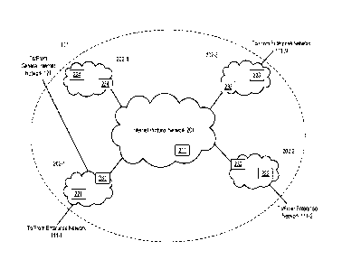
[Pols] Figure 1 depicts telecommunications system 100.
[0016] Figure 2 depicts wide-area network (WAN) 101 within telecommunications
system 100.
[0017] Figure 3 depicts Internet Protocol network 201 within WAN 101.
[oots] Figure 4 depicts a block diagram of the salient components of computer
system 211 within IP network 311.
[0019] Figure 5 depicts a message flow diagram of the salient processes for
allocating and sharing IP addresses
[0om] Figure 6 depicts a message flow diagram of the salient processes for
processing a stream of data based one or more of the allocated and shared IP
addresses.
Detailed Description
[0on] Figure 1 depicts telecommunications system 100, in accordance with the
illustrative embodiment of the present invention. Telecommunications system
100
comprises wide-area network 101, enterprise networks 111-1 through 111-N,
wherein N is
a positive integer, and general Internet network 121, interrelated as shown.
[0022] Wide-area network (WAN) 101 is wide-area-network¨based, in that it is a
telecommunications network that extends over a large geographical distance.
Because
WAN 101 in particular is an Internet WAN, it extends over the large
geographical distance
via at least some networking devices that are considered to be part of the
public Internet
and provides multi-location connectivity over the public Internet. WAN 101
comprises a
plurality of Internet service provider networks of various forms, and is
described in detail
below and with regard to Figure 2. An Internet service provider (ISP) is an
organization
that provides services for accessing, using, and/or participating in the
Internet. In some
embodiments of the present invention, an ISP provides services for accessing,
using, and/or
participating in public Internet. Some of the more specific classifications of
an ISP network
is "local", "tier 2", and "tier 1", as described elsewhere in this
specification. In some
embodiments of the present invention, a first ISP network is differentiated
from a second
ISP network, in that the first and second ISP networks require Border Gateway
Protocol
(BGP) in order to communicate with each other, while within the first ISP
network BGP is
not required (but possibly still used).
WO 2016/118498 PCT/US2016/013894
7
[0023] Enterprise network 111-n, wherein n can have a value between 1 and N,
inclusive, is a computer network (i.e., a first computer network, a second
computer
network, and so on) that comprises customer premises equipment (CPE) with
dedicated
Internet access (DIA). The CPE comprises one or more of user devices (e.g.,
personal
computer, personal digital assistant, smartphone, feature phone, etc.),
routers, switches,
residential gateways, fixed mobile convergence products, networking adapters,
and Internet
access gateways that enable the enterprise to access a communications service
provider's
services and distribute them around the enterprise to individual users via a
local area
network (LAN). Enterprise network 111-n can be used, operated, possessed,
and/or owned
by an enterprise (i.e., a business or company) or by a different entity. In
some
embodiments, at least some of the enterprise networks can be used, operated,
possessed,
and/or owned by the same enterprise and subscribed to one or more or the same
services.
[0024] General Internet network 121 is part of the Internet, the global system
of
interconnected computer networks that use the Internet protocol suite (TCP/IP)
to link
billions of user devices and networking devices worldwide. Specifically,
general Internet
network 121 is that part of the Internet which is not used by WAN 101 to
provide
connectivity amongst enterprise networks 111-1 through 111-N. As those who are
skilled in
the art will appreciate after reading this specification, at least some of the
infrastructure
that defines general Internet network 121 can be situated in the same
geographic region as
at least some of the infrastructure the defines WAN 101, or can be highly-
interconnected to
WAN 101 infrastructure, or both.
[0025] Figure 2 depicts wide-area network (WAN) 101 within telecommunications
system 100. WAN 101 comprises local Internet service provider (ISP) networks
202-1
through 202-M, wherein M is equal to four as depicted, and Internet Protocol
(IP)
network 201. The ISP networks and IP network 201 make up at least a portion of
the public
Internet.
[0026] Local Internet service provider network 202-m, wherein m can have a
value
of between 1 and M, inclusive, provides user devices of its end users with
access to
WAN 201 and general Internet 121. More generally, and consistent with the
description of
an ISP above, ISP network 202-m provides connectivity for accessing, using,
and/or
participating in the Internet. As depicted, the local Internet service
provider networks are
part of WAN 101; however, in some other embodiments, one or more of the local
service
provider networks can be separate from WAN 101. Four ISP networks 202-1
through 202-4
are depicted as constituting WAN 101. As those who are skilled in the art will
appreciate
WO 2016/118498 PCT/US2016/013894
8
after reading this specification, however, WAN 101 can comprise any number of
ISP
networks. More generally, local 'SP network 202-m can be referred to as "local
service
provider network 202-m".
[0027] Each local ISP network comprises one or more computer systems, such as
computer systems 221 through 224 corresponding to ISP networks 202-1 through
202-4,
respectively, as well as other computer networking equipment. Each computer
system
represents a system of one or more interconnected computers such as a server
computer,
for example and without limitation. Computer systems 221 through 224 are
described
below. Two or more local ISP networks promote robust connectivity to one
another, in part
through service-level agreements (SLA) and encryption.
[0028] In some embodiments of the present invention, each local 'SP network is
distinguished from other networks in WAN 101, by at least one edge router
being arranged
between the local ISP network and IP network 201 or between the local ISP
network and
any other public network in general. As depicted, edge router 231 sets such a
boundary for
(i.e., demarcates) local ISP network 202-1, edge router 232 demarcates network
202-2,
edge router 233 demarcates local ISP network 202-3, and edge router 234
demarcates local
ISP network 202-4.
[0029] Internet Protocol network 201 comprises one or more tier 1 and/or tier
2
service provider networks, and is described below and with respect to Figure
3. IP network
comprises computer system 211, also described below.
[0030] Relevant to wide-area network 101 in general, Internet service
providers
establish the worldwide connectivity between individual networks at various
levels of scope.
Operating within enterprise networks 111-1 through 111-N, end users who only
access the
Internet when needed to perform a function or obtain information, represent
the bottom of
the Internet routing hierarchy. At the top of the Internet routing hierarchy
are the tier 1
networks, including tier-1 network 311 described below and with respect to
Figure 3, large
telecommunication companies that exchange traffic directly with each other via
peering
agreements. In at least some embodiments of the present invention, a tier 1
network can
reach every other network on the Internet without purchasing IP transit or
paying
settlements; by this definition, a tier 1 network is a transit-free network
that peers with
every other tier 1 network. Tier 2 and lower level networks buy Internet
transit from other
providers to reach at least some parties on the global Internet, though they
might also
engage in peering. An Internet service provider may use a single upstream
provider for
connectivity, or implement multihoming to achieve redundancy and load
balancing.
WO 2016/118498 PCT/US2016/013894
9
Internet exchange points are major traffic exchanges with physical connections
to multiple
Internet service providers.
[0031] Each of network 201 and networks 202-1 through 202-4 comprises computer-
networking devices, which can include gateways, routers, network bridges,
switches, hubs,
and repeaters. The computer-networking devices that constitute the networks
depicted in
Figure 2 can also include hybrid network devices such as multilayer switches,
protocol
converters, bridge routers, proxy servers, firewalls, network address
translators,
multiplexers, network interface controllers, wireless network interface
controllers, modems,
ISDN terminal adapters, line drivers, wireless access points, networking
cables, and other
related hardware.
[0032] At least some of the computer-networking devices that are present in
WAN 101 use routing tables in their operating system to direct IP packets to
the next-hop
router or destination. Routing tables are maintained by manual configuration
or
automatically by routing protocols. The end-user devices in each enterprise
network
typically use a default route that points toward an ISP providing transit,
while ISP routers
(e.g., edge routers 231-234, etc.) use the Border Gateway Protocol (BGP) to
establish the
most efficient routing across the complex connections of the global Internet.
[0033] Figure 3 depicts Internet Protocol network 201 within WAN 101.
IP network 201 comprises one or more tier-level service provider networks,
including
backbone IP network 311. Each service provider network in WAN 101 comprises
one or
more computer networking devices, including at least some of the same types of
networking
devices (e.g., routers, etc.) that are described above and with respect to IP
network 201.
As depicted, IP network 201 comprises computer system 211 and routers 301
through 309,
interconnected as shown. Although nine routers are depicted, network 201 can
comprise
any number of routers and networking devices in general. Backbone IP network
311 can be
alternatively referred to as a "backbone service provider network", which, in
some
embodiments of the present invention, can be specifically a backbone Internet
service
provider network.
[0034] Backbone IP network 311 comprises computer system 211 and routers 305
through 307. As described below and with respect to Figure 4, computer system
211
comprises a server computer and performs at least some of the controlling
tasks depicted in
Figure 5, and interworks with computer systems 221 through 224 in local ISP
networks 202-1 through 202-4, as described below. Although three routers are
depicted,
network 311 can comprise any number of routers and networking devices in
general.
WO 2016/118498 PCT/US2016/013894
Furthermore, in some alternative embodiments of the present invention, first
and second
networking devices that are part of a given service provider network (e.g.,
network 311,
etc.) might be separated by at least one networking device belonging to a
different service
provider network, through which one or more data packets must pass to get from
the first
networking device to the second.
[0035] As depicted, at least one computer-networking device is arranged
between a
networking device in network 311 and a local ISP network 202, wherein the
intermediate
computer-networking device belongs to a different service provider network
than
network 311. For example and without limitation, router 301 is arranged
between
router 305 and service provider network 202-1. As those who are skilled in the
art will
appreciate after reading this specification, however, there can be any number
of such
intermediate devices, or no intermediate device at all, between network 311
and a local ISP
network 202, in various combinations between network 311 and the various local
ISP
networks 202. Furthermore, where there are multiple intermediate devices
between
network 311 and a particular local ISP network 202, different sets of these
intermediate
devices can belong to different service provider networks.
[0036] In accordance with the illustrative embodiment, network 311 is a tier 1
IP
network. In some alternative embodiments of the present invention, however,
network 311
is a different type of service provider network, such as a tier 2 IP network,
for example and
without limitation.
[0037] IP network 311 is capable of coordinating quality-of-service- (QoS-)
enabled
IP service for traffic prioritization throughout wide-area network 201. As
video and voice
are latency-sensitive applications, it is inefficient to give file-sharing and
email applications
the same priority in the delivery. IP network 311 enables wide-area network
201 to provide
video, voice, and other latency-sensitive applications higher QoS to improve
the network
utility.
[0038] IP network 311 is further capable of coordinating managed encryption
throughout wide-area network 201. Secure communications can be achieved
through
traditional security technology, such as IPSec, or through other means. For
traditional
IPSec deployment, IP network 311 manages all the customer connections and
managed
routers. For non-entity country sites, IP network 311 manages the overall
provisioning,
fault reporting, trouble-shooting co-ordinations and billing as a complete
managed service.
IP network 311 is responsible for the overall IPSec tunnel configuration and
on-going
maintenance. This extends to support IPSec VPN clients running on PCs/Laptops,
tablets,
WO 2016/118498 PCT/US2016/013894
11
and smartphones. The managed encryption service provides tunnel-less
encryption without
encrypting the IP header to preserve the IP header information. The managed
encryption
platform can support regular key renewal mechanism to further increase the
security level
of the packets between two enterprise network endpoints.
[0039] Figure 4 depicts a block diagram of the salient components of computer
system 211 within backbone IP network 311, in accordance with the illustrative
embodiment
of the present invention. Computer system 211 comprises: processor 401, memory
402,
and network interface module 403, which are interconnected as shown.
[ma] Computer system 211 comprises at least one server computer that performs
at least some of the tasks disclosed herein. As those who are skilled in the
art will
appreciate after reading this specification, the hardware platform performing
at least some
of the tasks performed by computer system 211 can be embodied as a multi-
processor
platform, as a sub-component of a larger computing platform, as a virtual
computing
element, or in some other computing environment ¨ all within the scope of the
present
invention.
[0041] As those who are skilled in the art will appreciate after reading this
specification, computer system 211 can be a different type of apparatus than a
server
computer, and can be referred to by a different name such as a data-processing
system, a
computing device, or another type of hardware platform that comprises one or
more
processors, one or more memories, and one or more network interfaces, for
example and
without limitation.
[0042] Processor 401 is a general-purpose processor that is configured to
execute
operating system 411 and application software 412, and to populate, amend,
use, and
manage database 413, as described in detail below and in the accompanying
figures. For
the purposes of this specification, a "processor" is defined as one or more
computational
elements, whether co-located or not and whether networked together or not.
[0043] Memory 402 is non-transitory and non-volatile computer storage memory
technology that is well known in the art (e.g., flash memory, etc.). Memory
402 is
configured to store operating system 411, application software 412, and
database 413. The
operating system is a collection of software that manages computer system
211's hardware
resources and provides common services for computer programs, such as those
that
constitute the application software. The application software that is executed
by
processor 401 enables computer system 211 to perform at least some of the
functions
WO 2016/118498 PCT/US2016/013894
12
disclosed herein. Database 413 comprises information about one or more
allocated unique
IP addresses, as described below.
[0044] It will be clear to those having ordinary skill in the art how to make
and use
alternative embodiments that comprise more than one memory 402; or comprise
subdivided segments of memory 402; or comprise a plurality of memory
technologies that
collectively store the operating system, application software, and database.
[0045] Network interface module 403 comprises a network adapter configured to
enable computer system 211 to transmit information to and receive information
from other
parts of telecommunications system 100, via the networking devices throughout
WAN 101.
[0046] In regard to computer systems 231 through 234, each of these computer
systems is similar to computer system 211 described above and with respect to
Figure 4.
Each of these computer systems comprises at least one server computer that
performs at
least some of the tasks disclosed herein. As those who are skilled in the art
will appreciate
after reading this specification, the hardware platform performing at least
some of the tasks
performed by one or more of computer systems 231 through 234 can be embodied
as a
multi-processor platform, as a sub-component of a larger computing platform,
as a virtual
computing element, or in some other computing environment ¨ all within the
scope of the
present invention.
[0047] As those who are skilled in the art will appreciate after reading this
specification, any or all of computer systems 231 through 234 can be a
different type of
apparatus than a server computer, and can be referred to by a different name
such as a
data-processing system, a computing device, or another type of hardware
platform that
comprises one or more processors, one or more memories, and one or more
network
interfaces, for example and without limitation.
[was] Additionally, each local service provider network 202 can comprise
multiple
hardware platforms (e.g., server computers, etc.) that are part of computer
systems 231
through 234, wherein each hardware platform performs a different subset of the
tasks
disclosed herein. For example and without limitation, within local service
provider network
202-1, the tasks of i) accessing a database, ii) distributing a list of IP
addresses, and iii)
assigning an IP address from a database can be performed by any combination of
one or
more hardware platforms.
[0049] Figures 5 and 6 depict message flow diagrams that are representative of
an
operating scenario of telecommunications system 100. The operating scenario
features a
technique for identifying a communication (e.g., packet, datagram, frame,
cell, protocol
WO 2016/118498 PCT/US2016/013894
13
data unit, message, etc.) for routing purposes, with predetermined Internet
Protocol
addresses. As reflected in the message flow diagrams, WAN 101 provides a
dedicated and
deterministic route for customers in enterprise networks 111-1 through 111-N
for pre-
determined delivery over the public Internet. In particular, WAN 101 uses
specific BGP
attributes, such as local preference and community tagging, and selective IP
address
exchange among backbone network 311 and the local ISP networks, as described
below, to
enable deterministic routing. WAN 101 also provides a dedicated and
deterministic route for
enterprise customers to reach services that are provided within general
Internet
network 121, such as cloud service providers that include Google Cloud
Platform, for
example and without limitation.
[0050] The processes performed by telecommunications system 100 of the
illustrative embodiment are depicted in the drawings (i.e., Figures 5 and 6)
as being
performed in a particular order. It will, however, be clear to those skilled
in the art, after
reading this disclosure, that such operations can be performed in a different
order than
depicted or can be performed in a non-sequential order (e.g., in parallel,
etc.). In some
embodiments of the present invention, some or all of the depicted processes
might be
combined or performed by different devices than depicted. In some embodiments
of the
present invention, some of the depicted processes might be omitted.
[closu Figure 5 depicts a message flow diagram of the salient processes for
allocating and sharing IP addresses, in accordance with the illustrative
embodiment of the
present invention.
[0052] Each local service provider network 202-m can allocate a non-empty set
of IP
addresses to be associated with one or more predefined services discussed
herein, and
stores the set in its database. In accordance with the illustrative embodiment
of the
present invention, each local service provider network 202-m allocates its set
of IP
addresses independently of the other local service provider networks.
Accordingly, a first
set of IP addresses allocated by network 202-1, for example, and a second set
of IP
addresses allocated by network 202-2 might be disjoint with respect to each
other, might
intersect each other, might have a relationship of one being a proper subset
or superset
with respect to the other, and so on. Illustratively, computer system 221 of
service
provider network 202-1 performs this at task 501, and computer system 222 of
service
provider network 202-2 performs this at task 511.
[0053] In accordance with the illustrative embodiment of the present
invention, the
local service providers are prohibited from communicating with each other
directly in order
WO 2016/118498 PCT/US2016/013894
14
to achieve the desired, deterministic routing results. Thus, each local
service provider
network 202-m shares its allocated set of IP addresses via a central
coordinator so that the
other local service providers will recognize all of the sets of IP addresses
as being associated
with the predefined service or services. Backbone network 311 serves in this
role of central
coordinator and handling the sharing of IP addresses.
[0054] There are various techniques through which backbone network 311
facilitates
the sharing of the IP addresses. In a first technique, each service provider
network 202-m
provides its set of IP addresses to a central coordinator (e.g., computer
system 211 of
backbone network 311, etc.) automatically (e.g., via data packets as a set is
created/updated, etc.); then, the central coordinator automatically forwards
the IP
addresses from each of the service provider networks to all of the service
provider
networks. With respect to Figure 5, at task 502, computer system 221 in
network 202-1
transmits its set of IP addresses allocated at task 501, to computer system
211 in network
311 via message 503. This transaction can be handled via the mechanism in
Border
Gateway Protocol (BGP), which is used to announce new routes and to exchange
IP
addresses across any two local ISP networks. At task 504, computer system 211
than
broadcasts the received set of IP addresses to the other local service
provider networks,
such as to computer system 222 of network 202-2 via message 505 and to
computer
system 223 of network 202-3 via message 507.
[ooss] Likewise, at task 512, computer system 222 in network 202-2 transmits
its
set of IP addresses allocated at task 511, to computer system 211 in network
311 via
message 513. This transaction can be handled via the mechanism in Border
Gateway
Protocol (BGP) that is used to announce new routes. At task 514, computer
system 211
than broadcasts the received set of IP addresses to the other local service
provider
networks, such as to computer system 223 of network 202-3 via message 515 and
to
computer system 221 of network 202-1 via message 517.
[0056] Each computer system 221, 222, and 223 in the respective partner
networks
202-1, 202-2, and 202-3 that are participating in the predefined service
update their
databases with IP addresses associated with the predefined service when
additional sets of
IP addresses are received. As depicted in Figure 5, at task 518, computer
system 221
stores the IP addresses received in message 517 in its database. At task 506,
computer
system 222 stores the IP addresses received in message 506 in its database.
Computer
system 223 stores, at task 508, the IP addresses received in message 507 and,
at task 516,
the IP address received in message 515, in its database. In doing so, each
computer
WO 2016/118498 PCT/US2016/013894
system develops and maintains a pool (e.g., a first pool, a second pool, etc.)
of IF
addresses that are unique in that they are to be used for the predefined
service only. In the
long run, each pool maintained by each computer system contains the IP
addresses shared
amongst the partner local ISP networks.
[0057] As those who are skilled in the art will appreciate after reading this
specification, other distribution techniques are possible and different
combinations of
features among the different techniques are possible. For example, in a second
technique,
each service provider network 202-m provides its set of IP addresses directly
to the other
service provider networks, based on a central coordinator (e.g., computer
system 211, etc.)
having identified, to each service provider, the other service providers that
are participating.
In a third technique, each service provider network 202-m provides its set of
IP addresses
to a central coordinator (e.g., the service provider of backbone network 311,
etc.) manually
(e.g., via email from a technician, etc.); then, the central coordinator
manually provides the
IP addresses from each of the service provider networks to all of the service
provider
networks.
[0058] Figure 6 depicts a message flow diagram of the salient processes for
processing a stream of data based one or more of the allocated and shared IP
addresses in
depicted in Figure 5, in accordance with the illustrative embodiment of the
present
invention. In this scenario, a first user device operating within enterprise
network 111-1 is
attempting to communicate with a second user device operating within
enterprise
network 111-2 and according to a predefined service. The predefined service,
at a
minimum, comprises the use of deterministic routing through network 201 such
that the
data packets travel through at least one of the networking devices 305 through
307 within
backbone network 311. The predefined service, in some embodiments, can
comprise
additional features, such as encryption and/or adherence to service
parameters, as
described below. The predefined service is implemented via sets of programs
that execute
on one or more of the computer systems and/or networking devices described
herein.
[0059] At task 601, enterprise network 111-1 begins transmitting the stream of
data
packets originated by the first user device, via one or more messages 602.
[0060] Local service provider network 202-1 (e.g., in London) receives the
data
packets being received from network 111-1. Computer system 221 recognizes that
the
packets are from a customer (i.e., network 111-1) of the predefined service of
the
illustrative embodiment provided by network 311 and that the data packets are
to be sent
to enterprise network 111-2 according to the predefined service. More
specifically,
WO 2016/118498 PCT/US2016/013894
16
computer system 221 recognizes the source address and the destination of the
data packets
as both belonging to subscribers of the predefined service - namely networks
111-1 and
111-2. In some embodiments of the present invention, the source address and/or
the
destination address is represented as an IP address.
[0061] At task 603, and based on the aforementioned recognition of the
addresses,
computer system 221 of network 202-1 assigns a unique IP address with route
prefix (e.g.,
1.1.1.0/24) from an IF pool of addresses that are dedicated to the predefined
service and
that were previously allocated and shared in accordance with Figure 5, so that
all service
provider networks will known that this connection is to be performed in
accordance with the
predefined service. For example and without limitation, this assigned IP
address with route
prefix can serve to identify the originator of the communication as being part
of the
predefined service. In contrast, if data packets received from enterprise
network 111-1 are
not being sent to another enterprise network and in accordance with the
predefined service,
then the next IP address can be assigned in a conventional manner by computer
system 221. As a result of the IP address being assigned to the communication,
the IP
address is inserted into one or more of the data packets to be sent. In some
alternative
embodiments of the present invention, an addressing scheme is used without a
route prefix
being specified.
[0062] In some embodiments of the present invention, computer system 221
determines that the data packets that are to be sent to enterprise network 202-
2 according
to the predefined service and, as a result, also encrypts the data. In
contrast, computer
system 221 might not encrypt the data when the first user device within
enterprise network
111-1 instead is attempting to access websites within general Internet network
121 such as
"google.com".
[0063] If the received IP address is not an IP address corresponding to the
predefined service, the data packets are sent through the general Internet
network 121. On
the other hand, if the received IP address is an IP address that corresponds
to the
predefined service, network 202-1 at task 604 sends the data packets to
backbone
network 311, which then forwards the data packets to local service provider
network 202-2.
[0064] Because the predefined service is in effect for the current set of data
packets,
a particular route is determined in advance - in this example, one that
traverses any
intermediate networking devices, such as device 301, to backbone network 311,
which then
directs the data packets to local service provider network 202-2. Accordingly,
at task 604,
WO 2016/118498 PCT/US2016/013894
17
network 202-1 transmits the data packets to device 301 via messages 605 that
consists of
one or more messages, providing routing information to device 301 in the
process.
[0065] Notably, device 301 is within a service provider network that is
external to
any service provider network (e.g., network 202-1, network 311, network 202-2,
etc.) that
is a knowing participant of the predefined service. It is merely a device
within the public
Internet. As a result, device 301 does not recognize any such allocated and
shared IP
addresses that are dedicated to the predefined service. However, because
network 202-1 is
a knowing participant of the predefined service, and has provided sufficient
routing
information in messages 605, device 301 (along with possibly additional
"external" devices)
is able to route the data packets specifically to backbone network 311, which
does recognize
the data packets as those to be handled according to the predefined service.
[0066] At task 606, device 301 routes the data packets to device 305 via
messages
607. Devices 305, 306, and 307 within backbone network 311 successively
forward the
data packets. At task 608, device 307 routes the data packets to device 302
via messages
609. Notably, device 302 is within a service provider network that is external
to any service
provider network (e.g., network 202-1, network 311, network 202-2, etc.) that
recognizes
the allocated and shared IP addresses as being unique and dedicated to the
predefined
service. However, the routing information already accompanying the data
packets enable
device 302 (along with possibly additional "external" devices) to route the
data packets to
network 202-2.
[0067] At task 610, device 302 routes the data packets to local service
provider
network 202-2 via messages 611.
[0068] At task 612, computer system 222 of network 202-2 (e.g., in Hong Kong)
recognizes the IP address as an address dedicated to the predefined service
and, as did
computer system 221 of network 202-1, assigns its own unique IP address with
route prefix
(e.g., 3.3.3.0/24) from an P pool of addresses that are dedicated to the
predefined service
and that were previously allocated and shared in accordance with Figure 5.
[0069] At task 613, network 202-2 transmits the data packets to enterprise
network
111-2 via messages 614. Network 111-2 then delivers the data packets to the
second user
device (i.e., operating with network 111-2).
[0070] As the first and second user devices communicate with each other, those
service provider networks that are partner networks in the predefined service
recognize the
data going back and forth are to be treated according to the predefined
service due to the
WO 2016/118498 PCT/US2016/013894
18
unique IP addresses assigned by service provider networks 202-1 and 202-2 and,
as such,
are knowing participants.
[0071] In accordance with the illustrative embodiment of the present
invention,
backbone network 311, by coordinating and enforcing the predefined service,
provides
deterministic routing of traffic. In addition, network 311 is further capable
of guaranteeing
end-to-end service-level agreements (SLA) and providing enterprise-grade
customer service
and reporting. This is achieved by requiring each local provider network 202-m
to meet
certain service parameters so that the predefined service is further capable
of providing
certain functionalities to end users, such as voice and other functionalities.
These service
parameters can include one or more of the following, in any combination:
i. Network Availability - The network availability is defined as the
measured average
up-time of dedicated Internet access (DIA) service between the network to
network
interconnection point(s) established between local provider and Customer, and
each
Service Location, on a monthly basis. The value is computed as follows: (720
hours -
monthly unscheduled outage hours) / 720 hours X 100%. The total amount of
outage hours is computed as the cumulative outage time reports confirmed by a
local provider by means of trouble tickets throughout the month. The outage
time
starts when a ticket is opened in the local provider trouble ticket system and
ends
when the Service is restored.
ii. Packet Loss - Packet Loss shall be measured as the percentage of 100
byte packets
at 5 iterations of 100 trials, averaged over a one (1) month period (720
hours) lost
between the Local provider Core IP POPs (meaning from Local provider IP Core
Access Router to Local provider IP Core Access Router).
iii. Latency - Latency is defined as the round trip delay required for a
packet to travel
between the ingress and egress port at Local provider' Core IP POPs (meaning
from
one Local provider IP Core Access Router to another Local provider IP Core
Access
Router). Latency is measured using 100-bytes packets every five (5) minute
interval
time and averaged over one (1) month (720 hours).
iv. Jitter - Jitter is the delay variation of the packet arrival time. The
Local provider
measures the network jitter sending ten (10) 64-byte UDP packets every five
(5)
minutes interval time. Jitter measurement is calculated as an average of all
test
performed over a calendar month.
v. Delivery Time - The service provider guarantees that the service
installation date will
WO 2016/118498 PCT/US2016/013894
19
meet the ready-for-service date agreed upon in the Service Order.
vi. Mean Time to Restore - Mean Time to Restore (MTTR) is defined as the
average time
to restore network failures in a month. MTTR is measured dividing the total
amount
of outage hours, as stated above, by the number of outages registered and
confirmed by Local provider in the trouble ticket system during the month.
[0072] It is to be understood that the disclosure teaches just one example of
the
illustrative embodiment and that many variations of the invention can easily
be devised by
those skilled in the art after reading this disclosure and that the scope of
the present
invention is to be determined by the following claims.