Note: Descriptions are shown in the official language in which they were submitted.
TUBULAR STRUCTURES WITH VARIABLE SUPPORT
CROSS REFERENCE TO RELATED APPLICATIONS
This application is a non-provisional application from US 62/125,294,
filed January 20, 2015, and US 62/196,902, filed July 24, 2015.
BACKGROUND
These inventions relate to flexible shafts, including shafts having
lumens and to shafts tubular structures, including both of those that may be
suitable for transiting mammalian lumens, including vasculature and other
lumens, including for humans, to such structures having variable support, and
to catheters.
SUMMARY
In one example of lumenal members, a flexible lumenal member
includes an inner member and has an outer member outside of the inner
member. A medial member is between the inner and outer members, wherein
the outer member is collapsible about the medial member and wherein the
outer member and the medial member are configured such that collapse of
the outer member about the medial member increases a stiffness of the
assembly. In one configuration, the inner member includes a lumen, for
example which can receive a component, including but not limited to a
guidewire, dilator, therapeutic device, intervention device and/or other
components. In that or another configuration, the medial member can take a
number of configurations. In one example of a configuration of the medial
member, the medial member can be a stent, for example a stent that is
generally understood in the medical industry as being for implanting into a
body, or the medial member can be a skeleton or movable support structure
for example that may be bendable, flexible or otherwise movable, including
skeletons or movable support structures having linear or curving segments
separated by open spaces. The linear and/or curving segments can have a
repeating pattern or a non-repeating pattern. In any of the foregoing or
1
Date Recue/Date Received 2022-06-20
CA 02974502 2017-07-20
WO 2016/118671
PCT/US2016/014193
additional configurations, the medial member may be enclosed within an
envelope, for example one which prevents contact between the medial
member and vasculature into which the assembly can be inserted. In one
configuration, the medial member may be sealed within a cavity, in one
example an annular cavity, and in another configuration, the medial member
may be enclosed within a cavity that is fully sealed or closed but for one or
more fluid passageways for allowing fluid to enter and exit the cavity.
In another example of lumenal members, including any of the foregoing
examples and configurations, a flexible lumenal member includes an inner
member, over a portion of which an intermediate structural member extends.
An outer member extends over at least part, and in the present examples all,
of the intermediate structural member. In a relaxed state of the flexible
lumenal member, the intermediate structural member and the outer member,
the intermediate structural member has a first outer dimension, in at least
some examples an outer diameter, and the outer member has at least one
second inner dimension, in at least some examples an inner diameter, less
than the first outer dimension of the structural member. In such a
configuration, the outer member may be biasing or pressing against the
intermediate structural member toward the inner member. For example, the
outer member can have an uninflated or unexpanded configuration that
presses against the intermediate structural member. In one configuration, the
unassembled outer member in a relaxed configuration has an inner diameter
that is less than the outer diameter of the intermediate structural member in
the configuration of the intermediate structural member when it is positioned
on the inner member. In one example where the unassembled outer member
has an inner diameter less than the outer diameter of the intermediate
structural member when the outer member is in a relaxed configuration, the
outer member can be expanded or enlarged sufficiently to slide over the
intermediate structural member and positioned as desired, and then released,
in which case the outer member returns toward the relaxed configuration,
pressing on the intermediate structural member. For example, the outer
member is resiliently flexible. The intermediate structural member, either
alone or with the inner member, stops the further relaxation of the outer
member. With the final assembly, and when the apparatus is ready for use,
2
CA 02974502 2017-07-20
WO 2016/118671
PCT/US2016/014193
the intermediate structural member is under compression from the resiliency
of the outer member.
In another example of a lumenal structure, a lumenal element or a
tubular element may combine with one or more additional elements to form a
nested structure, at least two components of which may be concentric, at
least two components of which may be tubular, and in which one or more
structural support elements may be positioned intermediate the lumenal or
tubular element and an outer element. In one configuration of the structural
support element, the structural support element has a skeleton or framework
configuration, for example a plurality of interconnected straight or curved
elements separated by open spaces. In one example, a plurality of
interconnected straight or curved elements can be highly interconnected, or
sparsely interconnected or in between. The straight or curved elements can
be struts, each one of which can be interconnected at respective ends with
one or more other struts, at nodes. A node can have two struts, thereby
contributing to a more sparsely interconnected structure, three struts thereby
contributing to a greater interconnected structure, four struts contributing
toward a greater interconnected structure, and so on. Similarly, all nodes can
have the same number of struts, or there can be groups of nodes having
different numbers of struts where a given group has the same number of
nodes, which also contributes to the level of interconnectedness. The
structural support element can have articulating members, and/or may include
a cellular structure interconnected by one or more links, for example struts.
In
a number of examples, the structural support element can be a stent, for
example a stent that is generally understood in the medical industry as being
for implanting into a body, for any of a number of procedures. The stent can
be an open cell stent, closed cell stent, hybrid cell stent, slotted tube
stent, or
other stent configuration, including mesh tubes generally. Examples of a
stent include the flexible-expandable stent configurations shown in
US5,843,120. The structural support element is flexible, and returnable to its
original form without losing substantially the original form. It may also be
collapsible and expandable without losing substantially the original form.
In any of the examples of an intermediate structural member described
herein, the intermediate structural member can be positioned within an
3
CA 02974502 2017-07-20
WO 2016/118671
PCT/US2016/014193
enclosure, for example an outer tubular element, which enclosure is secured
to an inner lumenal element or tubular element such that the intermediate
structural member is between the enclosure and the inner lumenal element or
inner tubular element. The enclosure may be sealed while still permitting
fluid
communication with a source of pressurized fluid to enlarge or inflate, for
example with a liquid or a gas, the enclosure. In one example, the
enlargement occurs by way of expansion of the enclosure in the form of an
outer cover, for example an outer tubular element. In some examples, the
enlargement releases the intermediate structural member, allowing it to move
ra more freely.
In any of the examples of the intermediate structural members, medial
structural members, stents or tubular meshes referenced herein, such
structural member can include inner and/or outer peripheral surfaces that can
frictionally engage adjacent surfaces of the assembly. For example, with a
structural member extending between an inner tubular element and an outer
tubular element, the surfaces of the structural member contacting one or the
other of the inner tubular element and the outer tubular element can press
sufficiently into the surface or surfaces to help limit relative movement
therebetween. In some configurations, surfaces on the structural member can
be sufficiently well-defined to have a perceptible angle or non-round surface
that can help to limit relative movement between the structural member and
the adjacent tubular member. In other configurations, a surface finish on the
structural member can help to increase the frictional force required to move
the structural member and the adjacent contacting surface or surfaces relative
to each other. Such structural members can be metal, including but not
limited to nitinol, stainless steel and similar metals, polished or
unpolished, or
other materials.
In a further example, which may be configured with any of the
foregoing examples or configurations, the examples of intermediate structural
members may be used in a variable stiffness catheter. In one example, the
catheter has a first flexibility in one condition and a second flexibility in
a
second condition. The one condition can be an inflated outer envelope, outer
tube or outer element around a structural support element, which structural
support element is on a lumenal element of the catheter. The outer element
4
CA 02974502 2017-07-20
WO 2016/118671
PCT/US2016/014193
is enlarged or inflated to allow an increased flexibility in the catheter. The
outer element can be enlarged or inflated an amount sufficient to reduce a
surface area of contact between the outer element and the structural support
element, which may leave a surface area of contact between the outer
element and the structural support element of anywhere from 95% to zero. A
reduced surface area of contact can result in greater flexibility of at least
a
portion of the lumenal element, in the present example the catheter. Reduced
or zero surface area of contact between the structural support element and
the outer element increases the freedom of movement of the catheter in the
area of the structural support element, for example so that any contribution
of
frictional engagement between the structural support element and the outer
element is reduced or eliminated, with the remaining resistance to movement
being contributed by the structural support element itself, the inner lumenal
element and any surface area of contact between the two of them. If the
outer element is constricted, reduced, deflated or otherwise brought into
greater contact with the structural support element (for example by
withdrawing fluid or by otherwise applying vacuum or negative pressure or by
elastic tension in the outer element), flexibility of at least a portion of
the
lumenal element, the catheter in this example, is reduced, for example arising
from greater frictional contact between the outer element and the adjacent
surface or surfaces of the structural support element. In one configuration of
the foregoing, enlargement or inflation of the outer element occurs by
injection
or intrusion of a media, for example a fluid, for example a liquid such as
saline, into the area of the structural support element. The fluid pressure
can
be used to increase or enlarge the outer element for example increasing the
outer dimension of the outer element so that the inner surface of the outer
element no longer contacts one or more adjacent surfaces of the structural
support element. In one example, the outer element is enlarged or inflated
sufficiently to eliminate all contact with the structural support element. The
fluid can be a mixture of saline and contrast, a gas such as CO2, or other
appropriate fluids. In some configurations, release of the outer element from
the structural support element also helps to release the structural support
element from the inner lumenal element of the catheter, for example to reduce
5
CA 02974502 2017-07-20
WO 2016/118671
PCT/US2016/014193
or eliminate frictional engagement between the structural support element and
the adjacent surface of the inner lumenal element of the catheter.
In a further example, which may be configured with any of the
foregoing examples or configurations, the examples of intermediate structural
members, may be used in a variable stiffness catheter whereby the stiffness
of a portion of the catheter is changed by pressing or contacting a structural
support element, which structural support element is contained within a cavity
or otherwise unremovable from the catheter without damaging the catheter,
and changed again by unpressing or removing contact with the structural
support element. In one example, the catheter has a structural support
element in a cavity of the catheter and fluid is used in the cavity to allow
or
remove contact with the structural support element as desired. In one
example, fluid is used to pressurize the cavity and reduce the amount of
contact with the structural support element, and reducing pressure increases
the amount of contact with a structural support element. In one example of
reducing pressure to increase the amount of contact with a structural support
element, an inherent resiliency in an outer element can be used to increase
contact between the outer element and the structural support element when
fluid pressure is reduced. Alternatively, an increase in pressure can be used
to increase frictional contact with such a structural support element,
depending on design of the assembly.
In another example, which may be configured with any of the foregoing
examples or configurations, the examples of intermediate structural members
may be used in a catheter having an inner lumenal member, a structural
support element, for example a stent, tubular mesh, or other structural
member, and the catheter may further include an outer tubular element over
at least part of the structural support element wherein the outer tubular
element is configured to be in a normally collapsed state. In one
configuration, the normally collapsed state is one that occurs through elastic
contraction of the material of the outer tubular element, and in one
configuration the elastic contraction applies pressure to the structural
support
element. Pressure against the structural support element produces a
frictional force between the structural support element and the material of
the
outer tubular element to inhibit movement therebetween. In one example, an
6
CA 02974502 2017-07-20
WO 2016/118671
PCT/US2016/014193
outer tubular element is expanded and placed over the structural support
element on the lumenal element, and then allowed to release or collapse
about the structural support element, for example configured to apply an
inward pressure on the structural support element. The outer tubular element
can be generally uniform in geometry and material throughout its length, but
also can have different characteristics incorporated into the outer tubular
element over its length and/or circumference, for example variations in
durometer, thickness, geometry as well as construction (for example single
piece versus multiple piece).
In a further example, which may be configured with any of the
foregoing examples or configurations, intermediate structural members may
be used in a catheter having an inner lumenal member, an outer tubular
member, and a structural support member positioned between the inner
lumenal member and the outer tubular member whereby increasing or
decreasing contact between one or more surfaces of the structural support
member with one or both of the inner lumenal member and the outer tubular
member changes a stiffness of a portion of the catheter. Increasing or
decreasing contact can be done by inflation or enlargement, for example
inflation or enlargement of the outer tubular member and/or the inner lumenal
member, for example sufficient to decrease the surface area of contact of one
or more elements with one or more surfaces of the structural support member.
In one example, flexibility of the catheter can be increased by enlarging the
outer tubular member relative to the structural support member, for example
by injection of fluid into a cavity around the structural support member.
Flexibility of the catheter can be decreased by reducing the enlargement, for
example by removing fluid from a cavity around the structural support
member.
In another example, which may be configured with any of the foregoing
examples or configurations, a catheter has a tubular mesh having a plurality
of longitudinally extending struts interconnected by a plurality of connecting
struts. Individual ones of the plurality of connecting struts can connect
respective circumferentially or arcuately spaced longitudinal struts. In one
example, a series of aligned longitudinal struts are circumferentially or
arcuately spaced from another series of aligned longitudinal struts, and
offset
7
CA 02974502 2017-07-20
WO 2016/118671
PCT/US2016/014193
longitudinally. In another example, respective angles between a connecting
strut and a respective longitudinal strut are acute angles. The acute angles
can be angles anywhere between greater than zero and less than 900
.
In a further example, which may be configured with any of the
foregoing examples or configurations, an intermediate structural member may
be used between the inner and outer tubular elements for providing variability
in stiffness of the assembly. In one configuration, the intermediate
structural
member is a flexible cylindrical member comprising a plurality of elements
wherein a transverse cross-section of the flexible cylindrical member includes
at least two, and in many examples at least three, elements arranged around
the cylinder. In one configuration, the plurality of elements are interlinked
or
interconnected within the intermediate structural member. In a further
configuration, the plurality of elements have discrete lengths, and in another
configuration each of the plurality of elements have lengths that are less
than
the overall length of the structural support member, and in one configuration
none of the plurality of elements extend proximally to a manual control
apparatus or to a proximal catheter hub. In another configuration, the
plurality
of elements are different sizes, and may include different cross-sectional
areas, and the plurality of elements may be identifiable in groups, one group
having the same characteristics different from those in another group, for
example different cross-sectional areas, different sizes, different lengths,
and
the like. In one example, there is a larger number of elements from one group
in the intermediate structural member than the number of elements from
another group. In one example, the plurality of elements are uniformly
distributed over the cylinder when in a relaxed or neutral state. In one
example, the intermediate structural member includes two groups of
interconnected elements, the first group arranged in a transverse cross-
section to have a first number of elements substantially evenly distributed
about the cylinder, and the second group to have a second number of
elements substantially evenly distributed, in one configuration six from the
first
group and 12 from the second group. The plurality of elements forming the
intermediate structural member in one example are arranged in a substantially
symmetrical form when in the relaxed or neutral configuration.
8
CA 02974502 2017-07-20
WO 2016/118671
PCT/US2016/014193
In a further example, which may be configured with any of the
foregoing examples or configurations, a variable stiffness shaft, for example
tubular elements lumenal elements, catheters, and the like, may include a
structural support member arranged relative to the shaft such that the shaft
can be changed from a first shape configuration, such as a shape
configuration as manufactured, to a second different shape configuration and
the structural support member helps to keep the shaft in the second shape
configuration. The structural support member can help to keep the shaft in
the second shape configuration even in spite of application of some external
to forces, or even in spite of manufactured memory such as the original
manufactured shape. In one configuration, the structural support member can
be in a first configuration, for example a released or flexible configuration,
and
the shaft in the location of the structural support member can be changed or
reshaped to a second shape configuration at which the structural support
member is then fixed or stiffened, clamped or sandwiched to retain its than
configuration. As a result, the shaft in the area of the structural support
member then maintains its second shape configuration, and that portion of the
shaft is inhibited from returning to its first shape configuration, even in
the
presence of external forces on the shaft or inherent memory in the first
configuration. In one example, a catheter can be introduced into a tortuous
body lumen with a structural support member associated with the catheter in a
released or flexible configuration. Once the catheter is in the desired
position
within the body lumen, with whatever twists and turns imposed on it while
transiting the body lumen, the structural support member can be stiffened,
clamped or sandwiched in its then-existing second shape, and that portion of
the catheter associated with the structural support member is held in the
same shape. During stiffening or while the catheter portion has an increased
stiffness, little or no force is applied to the vessel walls by the catheter.
Therefore, the structural support member helps to impose on that portion of
the catheter the shape of the body lumen in which it is positioned, giving
that
portion of the catheter a shape memory that is maintained even in the
presence of external forces and/or any shape memory instilled at
manufacture. An outer tubular element also helps to fix, stiffen, clamp or
sandwich the structural support member in these examples. Therefore, a
9
CA 02974502 2017-07-20
WO 2016/118671
PCT/US2016/014193
flexible shaft element, including medical catheters, can be stiffened and
maintained in a large number of shapes configurations regardless of a starting
shape configuration or manufactured shape configuration.
As used herein, "outer" in the context of outer tubular member, outer
member, outer element, outer cover, outer envelope or outer wall refers to a
position relative to the structural support member, and "outer" in this
context
does not mean outer-most.
These and other examples are set forth more fully below in conjunction
with drawings, a brief description of which follows.
BRIEF DESCRIPTION OF THE DRAWINGS
FIG. 1 is a side elevation view of a catheter assembly in accordance
with one aspect of the present inventions.
FIG. 2 is a longitudinal cross section of the catheter assembly of FIG.
1.
FIG. 3 is a detail of the cross section of the assembly of FIG. 2.
FIG. 4 is a detail of the cross-section illustrated in FIG. 3.
FIG. 4A detail of a portion of the cross section of FIG. 4 taken at 4A.
FIG. 5 is a longitudinal cross section of the catheter assembly of FIG. 1
with a portion of the catheter enlarged or inflated.
FIG. 6 is a detail of the enlarged or inflated portion of the catheter
assembly illustrated in FIG. 5.
FIG. 7 is a longitudinal cross section of a portion of the catheter
assembly of FIG. 1.
FIG. 8 is a longitudinal cross section of another example of a catheter
assembly.
FIG. 9 is a longitudinal cross section of the catheter assembly of FIG. 8
with a portion of the catheter enlarged or inflated.
FIG 10 is an isometric view of a portion of a catheter assembly.
FIG. 11A is a transverse cross-section of the catheter portion of FIG.
10.
FIG. 116 is a detail of a section of the catheter portion of FIG. 10 taken
at an angle as illustrated in FIG. 11A, though not necessarily at the axial
location illustrated in FIG. 11A.
CA 02974502 2017-07-20
WO 2016/118671
PCT/US2016/014193
FIG. 12 is a schematic of a mesh pattern for use as a structural support
element for a catheter.
FIG. 13 is a transverse section of two struts in the mesh pattern taken
along line 13-13 of FIG. 12.
FIG. 14 is a schematic representation of a tubular mesh formed using
the pattern of FIG. 12.
FIG. 15 is a schematic representation of the tubular mesh of FIG. 14 in
a loaded or bent configuration.
FIG. 16 is a schematic representation of a mesh pattern for use as a
structural support element.
FIG. 17 is a schematic representation of a further mesh pattern for use
as a structural support element.
FIG. 18 is a schematic representation of a catheter assembly in
vasculature, for example human vasculature, with a guide element.
FIG. 19 is a schematic representation of a catheter assembly in the
vasculature of FIG. 18 advanced with the assistance of a guide element.
FIG. 20 is a schematic representation of a catheter assembly in the
vasculature of FIG 18 with an intervention device in place.
FIG. 21 is a schematic representation of a mandrel and a catheter shaft
being assembled there on.
FIG. 22 is a schematic representation of the schematic of FIG. 21 with
a structural support element assembled there on.
FIG. 23 is a schematic representation of the assembly of FIG. 22 with a
balloon inflation and assembly apparatus.
FIG. 24 is a schematic representation of the assembly of FIG. 23 with a
tubular element inflated.
FIG. 25 is a schematic representation of the assembly of FIG. 24 with
the mandrel assembly being inserted into the inflated tubular element.
FIG. 26 is a schematic representation of the assembly of FIG. 25 with
the mandrel inserted into the inflated tubular element and the tubular element
deflated.
FIG. 27 is a schematic representation of the mandrel assembly of FIG.
21 with the catheter assembled there on.
11
CA 02974502 2017-07-20
WO 2016/118671
PCT/US2016/014193
FIG. 28 is a schematic representation of a further mandrel assembly
with the catheter assembled there on configured to provide the catheter for an
interference fit with a dilator assembly.
DETAILED DESCRIPTION
This specification taken in conjunction with the drawings sets forth
examples of apparatus and methods incorporating one or more aspects of the
present inventions in such a manner that any person skilled in the art can
make and use the inventions. The examples provide the best modes
contemplated for carrying out the inventions, although it should be understood
that various modifications can be accomplished within the parameters of the
present inventions.
Examples of lumenal or tubular structures and of methods of making
and using the lumenal or tubular structures are described. Depending on
what feature or features are incorporated in a given structure or a given
method, benefits can be achieved in the structure or the method. For
example, tubular structures using inner and outer tubular elements, which
may but need not be concentric, may be configured to have one stiffness in a
first state and another stiffness in another state, for example may be
configured to be relatively rigid when in a relaxed state, and less rigid when
one or more elements in the tubular structures are activated. Inner and outer
tubular elements can also be configured with an intermediate structural
framework that can provide a more reliable support assembly when in a
support configuration, for example when the inner and outer tubular elements
and the structural framework are pressed together. Configurations of inner
and outer tubular elements may also be used to more securely releasably fix
the tubular elements in a desired geometry, for example to support passage
of another element, for example an interventional device or other device,
during a procedure.
Examples of inner and outer lumenal element or tubular elements and
intermediate structural frameworks can also be used to provide a more
reliable support structure per unit length of an assembly of the tubular
elements and structural framework. Elements of one or more of the inner and
12
CA 02974502 2017-07-20
WO 2016/118671
PCT/US2016/014193
outer tubular elements and structural framework can be configured to
incorporate a desired flexibility or stiffness per unit length. In one
example, a
structural framework can be used intermediate the inner and outer tubular
elements that provides a given flexibility or stiffness per unit length, and a
different structural framework can be used to manufacture or assemble
another combination having a different flexibility or stiffness per unit
length. In
another example, a structural framework can be used to provide a given
flexibility or stiffness as a function of inflation or deflation of a
component
adjacent the structural framework. In one configuration, the structural
framework can provide an increased stiffness when an adjacent component
presses against it, for example when deflation brings the component into
contact with the structural framework, and can provide a decreased stiffness
when the adjacent component has a reduced amount of contact with the
structural framework.
In some configurations of lumenal or tubular structures, improvements
can be achieved also in assembly, and in some configurations, assemblies
can be produced having an assembled or final configuration with a desired
stiffness or flexibility, and wherein such stiffness or flexibility can be
selectively or intermittently reduced through one or more actions. For
example, an assembly can be produced where a component in a relaxed or
natural state presses against a structural framework, in one example where a
resilient tubular structure presses against a structural framework. In another
example, a user can reduce a stiffness or flexibility in an assembly by
releasably inflating or enlarging at least one of the tubular structures,
which
can reduce a stiffness or flexibility in at least part of the assembly.
These and other benefits will become more apparent with
consideration of the description of the examples herein. However, it should
be understood that not all of the benefits or features discussed with respect
to
a particular example must be incorporated into a tubular structure, component
or method in order to achieve one or more benefits contemplated by these
examples. Additionally, it should be understood that features of the examples
can be incorporated into a tubular structure, component or method to achieve
some measure of a given benefit even though the benefit may not be optimal
compared to other possible configurations. For example, one or more
13
CA 02974502 2017-07-20
WO 2016/118671
PCT/US2016/014193
benefits may not be optimized for a given configuration in order to achieve
cost reductions, efficiencies or for other reasons known to the person
settling
on a particular product configuration or method.
Examples of a number of tubular structure configurations and of
methods of making and using the tubular structures are described herein, and
some have particular benefits in being used together. However, even though
these apparatus and methods are considered together at this point, there is
no requirement that they be combined exactly as described, used together in
the exact combinations, or that one component or method be used only with
the other components or methods, or combinations as described.
Additionally, it will be understood that a given component or method could be
combined with other structures or methods not expressly discussed herein
while still achieving desirable results.
Catheters are used as examples of a tubular structure that can
.. incorporate one or more of the features and derive some of the benefits
described herein, and in particular vascular catheters. Catheters used for
navigation and for support for other components in vessels have a number of
configurations, and such catheters can benefit from one or more of the
present inventions. Tubular structures other than catheters can benefit from
.. one or more of the present inventions.
As used herein, "substantially" and "approximately" shall mean the
designated parameter or configuration, plus or minus 10%.
A lumenal or tubular structure can be incorporated into a number of
devices, which may include apparatus and methods for varying the stiffness
or flexibility of, or support provided by, such lumenal or tubular structure.
The
present examples described herein relate to lumenal or tubular structures for
catheters, for example catheters for traversing vasculature, including human
vasculature. However, it is understood that the components and assemblies
described herein can be used in a variety of structures and applications,
.. including catheters for other applications, and other lumenal or tubular
structures. The present examples will include vascular catheters, but other
structures are applicable as well.
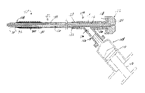
In one example of a lumenal or tubular structure (FIGS. 1-7), a catheter
assembly 100 includes a catheter having a shaft 102. The catheter assembly
14
CA 02974502 2017-07-20
WO 2016/118671
PCT/US2016/014193
100 is configured to be sufficiently flexible to transit human vasculature.
The
catheter assembly further includes a catheter hub 104. The catheter hub can
take a number of configurations, and may be used to receive and provide a
number of structures and components and/or fluids in the use and application
of the catheter, and may be used with a number of other instruments and/or
components as would be understood to one of ordinary skill in the art. In the
present example, the catheter hub includes an inflation or injection port 106
for receiving an injection or inflation device, in the present example
denominated as syringe 108 having a syringe body or barrel 110 and plunger
r.o 112, for example for injecting and withdrawing fluid from or into the
barrel 110.
The syringe will be used to hold and inject or withdraw saline into or from
the
catheter hub 104 or lumen (in the example of FIGS. 8-9 described more fully
below). The syringe is mounted or secured in the inflation port 106 in a
conventional way.
The catheter hub 104 includes a main body 114 extending
longitudinally and defining in part a main axis of the catheter hub, at the
proximal portion of the catheter. The catheter hub body 114 includes an
internal wall defining a bore 116 extending from a proximal end 118 of the
catheter hub to a distal end 120 of the catheter hub, and is configured in a
conventional manner for receiving devices and materials, and may receive in
the present example a dilator 122 as illustrated. The dilator can be omitted,
or
replaced by a cover or by other components. In the present example, the
dilator 122 includes a dilator hub 124 mounted on or secured to the proximal
end 118 of the catheter hub, and a dilator shaft 126 extending longitudinally
of
the catheter hub inside the wall 116 and within the catheter shaft 102. In the
present example, the dilator shaft 126 extends through a distal end portion
128 of the catheter shaft and includes a dilator tip 130. In the present
example, the dilator tip extends beyond a distal end surface 132 of the
catheter shaft, for example a distance typical for catheter and dilator
assemblies. The dilator 122 is a conventional dilator, configured for use with
a catheter such as any of those described herein. In one example, the dilator
is configured for receiving a guidewire or other guide device (not shown)
through the central lumen of the dilator.
CA 02974502 2017-07-20
WO 2016/118671
PCT/US2016/014193
The inflation port 106 includes an internal wall 134 defining a bore
extending to the central bore 116 of the catheter hub. The inflation bore 134
is in fluid communication with the central bore 116, and fluid from the
inflation
port 106 can flow into and out of the central bore 116 around the dilator
shaft
with the operation of the syringe 108, as well as under the influence of any
other forces or influences in the design of the catheter. An interference fit
between the dilator distal end and the catheter shaft distal end keeps fluid
in
the central bore 116.
The catheter shaft 102 includes a lumenal member, in the present
r.o example a tubular member 150. A proximal portion 152 of the tubular
member 150 is mounted, secured and sealed in the distal portion 120 of the
catheter hub in a conventional manner. The tubular member extends
longitudinally from the catheter hub to the distal end portion 128 of the
catheter shaft, and specifically terminates in the present example at the
distal
end surface 132. The tubular member is formed so as to be sufficiently
flexible for transiting human vasculature and body lumens, including cardiac,
peripheral, and cerebral vasculature, which can be tortuous. The tubular
member 150 in the present example has a substantially circular cross-section,
but can have other cross-sectional profiles. The tubular member is
substantially coaxial with the central axis of the catheter hub 104 when in
the
shape as illustrated in FIGS. 1 and 2.
The tubular member 150 is substantially cylindrical over substantially
its entire length. The tubular member also has a substantially uniform wall
thickness over substantially its entire length, for example 0.003" ¨ 0.020",
and
it also has a substantially uniform inner diameter, for example 0.025" ¨
0.100",
over its entire length from inside the catheter hub up to just proximal of the
distal end portion 128, which is described more fully below. However, it is
understood that other tubular geometries can be used, and the catheter shaft
can be formed with other cross-sectional profiles. Alternatively, the catheter
shaft 102 can have other constructions and geometries than those described
herein, and such other constructions and/or geometries may include lumens,
as desired, for example for passage of apparatus or fluids, such as guide
wires, tubular devices, instruments, saline, contrast, and other devices and
materials.
16
CA 02974502 2017-07-20
WO 2016/118671
PCT/US2016/014193
The tubular member 150 is formed from a suitable material, which may
be determined by the intended application. In the present examples, the
tubular member 150 is formed from an elastomeric material conventional for
vascular catheters, for example PEBA, polyurethane, or similar. The internal
and external surfaces of the tubular member are configured to have the
desired finishes for their intended purposes. In the present example, the
outside surface 154 (FIG. 3) permits easy movement through other devices
and through vasculature, as necessary. The inside surface 156 permits fluid
flow within the tubular member and easy movement of the dilator shaft 126
and any other devices or materials as desired, such as interventional
devices/instruments.
In the illustrated example, the tubular member 150 includes
strengthening elements. In the present example, the strengthening elements
include one or more helical coil structures 158 (FIGS. 3 and 4). In the
present
example, the helical coil 158 is a single continuous helical coil extending
from
inside the catheter hub 104 to a point adjacent the distal end portion 128 of
the tubular structure. The helical coil can take the form of conventional
reinforcement for conventional catheter tubes, and may be stainless steel, for
example 304 or 316 stainless steel, with a diameter of 0.001" ¨ 0.007", and a
pitch of 0.003" ¨ 0.020". Furthermore, the coil may be formed from a wire with
a non-circular shape in cross section, such as a rectangle or oval cross
section. The coil can be formed from other materials, with other coil and
strand diameters and/or with other pitches, to provide the desired strength,
reinforcement and/or stiffness. Other strengthening devices can be used,
either alternatively or additionally. For example, braid structures can be
used.
In the present example, the strengthening elements are embedded in or
coextruded with the tubular member 150, for example as would be
conventional.
The tubular member 150 extends distally to the distal end portion 128,
where the coil 158 terminates. The elastomeric tubular member continues
distally at a converging portion 160, which then terminates at a cylindrical
or
annular wall portion 162. The distal end portion 128 is formed with a diameter
so as to provide an interference fit with the dilator tip 130, both of which
are
configured to provide the desired interference fit.
17
CA 02974502 2017-07-20
WO 2016/118671
PCT/US2016/014193
The tubular member 150 geometry and structure in the present
example extends uninterrupted from the proximal to the distal end portions
except for one or more apertures or fluid openings 164 (FIGS. 3-4). The
apertures 164 extend completely through the tubular wall between strands of
the coil and provide a fluid path between the inside and the outside of the
tubular member at a location of the openings, which in the present example
are within an outer tubular member described more fully below. The fluid
openings allow fluid to pass from the lumen within the tubular member 150,
for example fluid from the inflation port 106, to a cavity or recess or
balloon
outside the tubular member 150. In the present example, there are two fluid
openings through the wall of the tubular catheter member.
Use of fluid to expand and/or contract the volume of a cavity containing
a structural support element allows changing conditions of the tubular
structure. For example, inflation and deflation or reduction in pressure or
application of vacuum can change a stiffness or flexibility of a structure. In
one example, inflating a cavity containing a structural support element can
increase the flexibility of the catheter in the area of the structural support
element, and reducing the pressure, applying vacuum or allowing deflation of
the cavity can decrease the flexibility of the catheter. In this way, the
catheter
can have a selective adjustability of its stiffness or flexibility.
The configuration of the tubular member 150, as the inner layer or
inner tubular element, can be configured in a number of ways. Flexibility can
be enhanced along the length, including in the distal portion of the tubular
element, by changing the durometer of the material as a function of its
length,
and/or adjusting the wall thickness of the tubular member as a function of
length or distance from the catheter hub. Alternatively and/or additionally,
the
reinforcement can be modified as a function of distance from the catheter hub,
for example by changing the geometry or the spacing of the material. In the
example of a helical coil, the pitch of the coil can be changed, or the
diameter
of the coil or strand element embedded in the tubular member. The
reinforcement material can be metal or non-metal, and may be stainless steel,
nitinol, polymeric fiber, metallic wire with a radio opacity property,
tantalum,
tungsten, or alloys of these materials or other materials.
18
CA 02974502 2017-07-20
WO 2016/118671
PCT/US2016/014193
The catheter 100 further includes an adjustable member outside of the
catheter tubular member 150, extending over at least a portion of the outer
surface of the tubular member 150. In the area of the adjustable member, the
catheter tubular member 150 is an inner tubular member relative to the outer
adjustable member. In some configurations, the adjustable member is used
to selectively establish or change a flexibility or stiffness of a portion of
the
catheter, for example the portion of the catheter around which the adjustable
member is positioned. The adjustable member can be used to sandwich one
or more underlying components within an envelope, cavity or area over or
around which the adjustable member extends. The adjustable member can
be used to increase surface areas of contact between adjacent elements, and
to establish or increase internal forces that must be overcome to move or
change a geometry of a portion of the catheter. The adjustable member can
also be used to effectively separate itself from a portion or all of an
underlying
component, which may allow separation of additional components from each
other, and which may also allow position adjustments or other adjustments of
one or more underlying components. The adjustable member can be
configured to be normally in a first condition or normally in a second
condition
(for example having a memory characteristic), for example normally producing
contact with underlying components or normally separating from underlying
components, or normally applying pressure or normally released from
applying pressure. Alternatively, the adjustable member can be configured to
remain in a given state until acted upon, for example without any memory
characteristic. In the examples described herein, the adjustable member is
configured to be normally in a collapsed, reduced or application mode where
pressure or force is applied by the adjustable member to one or more
underlying components. The adjustable member is adjusted by positive
action to change the adjustable member from its collapsed, reduced or
application mode at least in part, for example to reduce a surface area of
contact between the adjustable member and an underlying component. In the
present examples, the adjustable member is movable radially. Also in the
present examples, the adjustable member applies pressure to an underlying
component along the entire length of the underlying component substantially
simultaneously.
19
CA 02974502 2017-07-20
WO 2016/118671
PCT/US2016/014193
An example of an adjustable member (FIGS. 1-9 and 11A-B) is tubular
member 200. In the present example, the tubular member 200 extends over
a portion of the catheter shaft 102. The tubular member 200 forms an outer
tubular member (outer tube) to the extent that it is outward of the adjacent
portion of the catheter shaft 102. However, it is understood that one or more
other components can be outward of the outer tubular member 200. A
proximal end 202 of the outer tube is secured to an adjacent portion of the
catheter tubular member 150, circumferentially around the entire portion of
the
proximal end 202 of the outer tube. The proximal end can be sealed, welded,
bonded, for example thermally or adhesively, or otherwise secured to the
outer surface of the catheter tubular member 150, for example in a manner
similar to concentric catheter tubes may be secured to each other in
conventional catheters. With the present outer tube, the outer tube is secured
to the catheter tubular member 150 at both ends of the outer tubular element
in such a way that the junction can withstand expected internal fluid
pressures
developed between the outer tubular member and the catheter tubular
member 150.
The outer tube 200 extends distally from the proximal end portion 202
over the catheter tubular member 150 to a distal end portion 204 of the outer
tubular member, surrounding the distal end portion 128 of the catheter tubular
member 150. The distal end portion 204 is sealed, welded, bonded or
otherwise secured to the adjacent distal end portion of the catheter tubular
member in the same manner as for the proximal end portion 202. The outer
tube 200 forms between the proximal and distal end portions a cavity,
envelope or annular space 206 between the inside surface 208 of the outer
tube 200 and the opposite or facing outer surface 154 of the inner tubular
member 150. The cavity 206 forms in the present examples a balloon which
can be enlarged or inflated as a function of the flexibility and strength of
the
outer tubular member 200. In some configurations, the adjacent portion of the
inner tubular member may also be sufficiently flexible to provide a measure of
additional inflation or enlargement, inwardly toward the central axis of the
catheter, but the present configurations have the inner tubular member 150
with the embedded coil 158 such that the wall of the inner tubular member
does not change diameter significantly under the presently contemplated
CA 02974502 2017-07-20
WO 2016/118671
PCT/US2016/014193
pressures within the cavity 206, and remains a constant diameter before,
during and after inflation or enlargement of the outer tubular element and an
before during and after deflation or full collapse of the outer tubular
element.
In the present example, the outer tube 200 is a monolithic structure,
and is formed from a material that is flexible and can increase in diameter
(i.e., increase in diameter where the outer tube is substantially cylindrical
or
circular) upon application of an internal pressure (for example between
approximately 1-200 psi) between the outer tube 200 and the inner tube 150.
The outer tubular element serves as a balloon that can expand outwardly
upon application of an internal pressure, for example pressure developed by a
fluid, in one example a relatively incompressible fluid. The outer tubular
element 200 is configured to have a maximum expandable diameter under
normal operating conditions for example by selecting a material that can
inherently expand or stretch to a selected or preferred diameter and maintain
that diameter even with possible expected higher pressures.
The outer tubular element 200 in the present examples is formed from
polyurethane, and has a wall thickness of approximately 0.003". In the
present examples, the outer tubular element 200 has a relaxed internal
diameter when originally formed and before assembly on the catheter of
approximately 0.100", when the other components inside the outer tubular
element are dimensioned as described herein. It has an expected inflated
internal diameter of 0.118". The material is preferably abrasion resistant,
and
highly resistant to puncture. The outer tubular element 200 in the present
examples has a structure similar to balloon catheters but without any folds or
creases, and can be produced in a manner similar to balloon blow molding
processes. In the present example, the outer tubular element 200 is formed
prior to assembly to be configured to be normally collapsed when assembled
in the catheter. Once installed and if the outer tubular member is enlarged or
inflated, the material of the outer tubular member is configured to produce an
elastic recoil when the pressure is reduced or removed. The outer tubular
member can be modified in a number of ways, but in the present examples is
configured to be uniform throughout its length. In other examples, the outer
tubular member can be configured to have different characteristics at
different
places along its length, for example based on durometer, thickness, the
21
CA 02974502 2017-07-20
WO 2016/118671
PCT/US2016/014193
original or relaxed or recovered shape and/or diameter, material and
thickness, and circumferential configuration. However, in the present
examples, the response of the outer tubular member to inflation or
enlargement pressure from an internal fluid is relatively uniform throughout
the outer tubular member, and reaches a predetermined outer diameter,
which is maintained even with higher pressures until pressure is removed and
the outer tubular member deflate, retracts or returns to the structural
support
element. In this way, inflation or expansion of the outer tubular element
allows disengagement of layers without overstretching the outer tubular
element. The outer tubular element can be configured to have a non-linear
pressure versus diameter relationship such that the diameter of the outer
tubular element can increase with pressure up to a predetermined diameter,
after which no further expansion occurs.
In the present examples, the catheter tubular member 150 and the
outer tubular element 200 form nested tubular structures which are
concentric, and together they define a cavity. Alternatively, they can be
other
than concentric, and they can have geometries other than cylindrical or
circular cross-sections.
Lumenal structures and tubular structures, including the tubular
catheter 100 can include support structures, for example medial or
intermediate support structures, that can provide stiffness to the lumenal and
tubular structures, and in the present examples, can provide selectable or
variable adjustable stiffness or flexibility to the lumenal and tubular
structures.
The support structure can be placed the entire length or at a number of
locations along the length of the lumenal and tubular structures, and in the
present examples, the support structure is positioned adjacent the distal end
of the catheter. In one configuration of the support structure and the lumenal
or tubular structure, the support structure can have an adjustable stiffness
or
modifiable stiffness configuration, which configuration can be affected by its
geometry and how it is combined with the lumenal or tubular structure. In one
configuration, the support structure is sandwiched or interposed between two
structures, one or both of which may be adjustable relative to the support
structure to change the stiffness of the assembly. In that or another
configuration, the support structure has surfaces contacting one or more
22
CA 02974502 2017-07-20
WO 2016/118671
PCT/US2016/014193
adjacent surfaces in the lumenal or tubular structure, which contact results
in
frictional forces if the support structure bends or otherwise changes its
configuration. The frictional forces resist the configuration change,
contributing at least in part to increased stiffness or decreased flexibility
of the
assembly, for example in the area of the support structure.
The support structure can take a number of configurations, and when
placed over a lumenal or tubular structure, the support structure can also be
a
tubular support structure. The support structure can take the form of a
tubular
mesh, including a non-random mesh configuration, a tubular skeletal
ra structure, a tubular framework, a tubular braid, a stent, for example
such
structures as medically implantable stents, and other structures. "Non-
random" as used herein in the context of a structural support element is one
that includes elements between the ends of the structural support element
that were configured in a selected or controlled way. In some configurations,
for example where the support structure is a tubular mesh, skeletal structure,
framework or stent, elements making up the support structure can have a
relatively high degree of interconnectedness, while still providing some
degree
of freedom of movement. In contrast to stents, however, the present support
structure does not expand radially or extend longitudinally substantially once
the catheter is assembled, other than what might occur on bending of the
catheter and therefore the support structure. In the art of stents, a
relatively
low degree of interconnectedness would be termed an open cell configuration,
and a relatively high degree of interconnectedness would be termed a closed
cell configuration, or one tending more toward a closed cell configuration
than
an open cell configuration. Higher levels of interconnectedness in a tubular
mesh, skeletal structure or framework may have more interconnections
between elements than fewer interconnections. Interconnectedness
contributes to an ability or inability of the support structure to move or
change
its geometry, with movement being easier with fewer interconnections, and
more difficult with more interconnections.
In addition to the inherent characteristics of the support structure to
allow or resist movement or changing geometry, interactions of the support
structure with adjacent surfaces also affects resistance to movement or
changing geometry. For example, larger surface areas of contact between
23
CA 02974502 2017-07-20
WO 2016/118671
PCT/US2016/014193
the support structure and adjacent surfaces give rise to frictional forces to
a
greater extent resisting movement or geometry changes than smaller surface
areas of contact. Support structures having larger numbers of components
with surface areas that can contact the adjacent surfaces will exhibit higher
resistance to geometry changes or movement than ones having smaller
numbers of components, all other things being equal. Similarly, the surface
characteristics of the components of support structures may also affect the
resistance to geometry changes or movement. For example, surface textures
or surface edges may contribute to higher frictional forces when in contact
with adjacent surfaces that may resist geometry changes or movement.
The catheter 100 includes an intermediate or medial support structure
300 (FIGS. 2-9). In the present example, the support structure 300 is a
monolithic structure having a tubular shape made up of spars, struts, or
linear
or curving limbs 302 interconnected with each other with open space 303 in
between to form the support structure 300, and the cross sections of FIGS. 2-
9 show cross sections of elements of the support structure 300 not to scale
with the pitch of the coil 158, with the understanding that the example of the
support structure 300 is shown in and described in more detail with respect to
FIGS. 10-13. The support structure is a three-dimensional configuration of
spars, struts, or linear or curving limbs and intermediate cavities or
openings
whose configuration can be selectively adjusted or changed and releasably
fixed in place as desired. The adjacent structures can be selectively coupled
and decoupled to provide support or tracking as desired. In the present
examples, three components are mechanically or frictionally decoupled to a
greater or lesser extent to allow selective changing or adjustment of the
configuration of the support structure, after which the three components can
be re-coupled, for example mechanically and with increased surface areas of
contact for frictional engagement.
In the present example, the support structure 300 is positioned
intermediate the tubular member 150 and the outer tubular member 200, in
the cavity or annular void 206 formed between the inner tubular member and
the outer tubular member 200. Also in the present example, the support
structure 300 extends substantially from the proximal end portion 202 of the
outer tubular element 200 to the distal end portion 204, and the configuration
24
CA 02974502 2017-07-20
WO 2016/118671
PCT/US2016/014193
of the support structure is substantially consistent over the length thereof.
However, the support structure can be configured to have different
configurations as a function of axial position and/or circumferential
position.
The support structure 300 can be secured to the outer surface 158 of the
inner tubular member 150, for example by tacking, adhesive, or other means,
such as at one or several endpoints at the proximal and distal ends of the
support structure. Such securement may assist in assembly, and such
securement can be eliminated prior to final assembly if desired. Conversely,
flexibility of the distal portion of the catheter can be reduced as a function
of
securement of the structural support 300 to the inner tubular member 150,
axially and/or circumferentially. However, such reduction generally would not
be reversible, and would decrease the baseline flexibility or increase the
stiffness of the distal portion of the catheter and it could be difficult to
increase
the flexibility above the baseline or reduce the stiffness.
The components of the structural support 300, such as the limbs 302,
can have a number of geometries. In the present example, each limb 302 has
a substantially rectangular cross-section with a long axis parallel to the
main
axis of the catheter, and short axis perpendicular thereto. Having the long
axis parallel increases the surface area of each limb that can contact an
adjacent surface 158 of the inner tubular member and the inner surface 208 of
the outer tubular member 200. However, other geometries can be used. In
the present example, each limb 302 of the support structure 300 is illustrated
in FIGS. 4 and 4A as being slightly spaced outward from the outer surface
158 of the inner tubular element 150. The support structure can be
configured to have a larger inside diameter in a relaxed state than an outside
diameter of the outer surface 158, which may then produce limited surface
contact between the structural support 300 and the inner tubular member 150
when first assembled. Alternatively, the support structure can be configured
to have an inside diameter in the relaxed state comparable or approximately
the same as the outside diameter of the outer surface 158, so that greater
surface contact occurs between the structural support and the inner tubular
member. In another alternative, the structural support 300 can be configured
to have a smaller inside diameter in the relaxed state, for example through an
inherent bias in the support structure, to have a higher surface area of
contact
CA 02974502 2017-07-20
WO 2016/118671
PCT/US2016/014193
with the inner tubular element in the relaxed state. Higher surface area of
contact promotes stiffness, relative to lower surface area of contact between
the support structure 300 and the inner tubular element 150.
As illustrated in FIG. 4, each limb 302 of the structural support 300 has
a relatively defined set of corners or angular transitions 304 from one side
to
an adjacent side. The corners 304 are exaggerated in their sharpness, but
the curvature of the transition between surfaces around a perimeter of a limb
can affect frictional forces arising through contact between a limb and an
adjacent surface, either with the outer surface 154 of the inner tubular
to element or with the inner surface 208 of the outer tubular element. The
quantity or extent and the quality of the edge contact between limbs and their
adjacent surfaces will contribute more or less to the stiffness or flexibility
of
the combination. All other things being equal, sharper or more angular
transitions between surfaces produce higher frictional forces and increased
stiffness or decreased flexibility. Therefore, a non-round limb profile on the
structural support 300 can enhance the stiffness or reduce the flexibility of
the
distal portion of the catheter when the structural support contact the
adjacent
surfaces. Similarly, textures on surfaces of the support structure contacting
adjacent surfaces of the tubular elements can also increase friction and
stiffness or decreased flexibility. For example, a nitinol structural support
300
that is not electro-polished may enhance the stiffness or reduce the
flexibility
of the distal portion of the catheter as a result of surface contact with the
adjacent surfaces of the inner and/or outer tubular elements.
The structural support element can be formed from a number of
materials, including stainless steel, nitinol, polymeric materials, and other
suitable materials. The structures can have cross sectional geometries that
are smooth or angular, and may be finished or unfinished, etched or not,
abraded or not (e.g., grit blasting), and for example with nitinol,
electropolished or not. A structural support element such as a stent will be
configured to have a structure, material, and characteristics of such a stent,
such as extends used for medical implantation.
The illustrations of catheters in FIGS. 1-9 show the catheter shaft
extending straight, in what is considered a neutral configuration. In such a
configuration, and as can be seen in FIG. 4, the outer surface 158 extends
26
CA 02974502 2017-07-20
WO 2016/118671
PCT/US2016/014193
axially substantially straight, and the adjacent surfaces of the limbs 302 of
the
support structure 300 extend substantially parallel to the outer surface.
Relatively little frictional engagement occurs in such a configuration between
the corners 304 and the outer surface 154 until such time as the catheter
bends. When the catheter bends, the concave portion of the bend may have
relatively higher contact and frictional engagement with the corners 304 of
the
adjacent limbs, for example at both corners of a limb, whereas in the convex
portion of the bend, fewer of the corners 304 might contact the adjacent outer
surface 154.
io The outer tubular element 200 is relatively more flexible than the inner
tubular element 150. In a configuration where the outer tubular element 200
is constricted, deflated, or otherwise pressed against the support structure
300, the flexibility of the outer tubular element 200 allows the inner surface
208 to somewhat conform to the adjacent surface of the support structure.
Specifically, the inner surface 208 extends over a limb 302 and curves or
bends around adjacent corners 304 it contacts. Additionally, the outer tubular
element 200 extends into the gaps or spaces 210 between adjacent limbs of
the support structure. Consequently, possible movement of the limb 302 to
the left as viewed in FIG. 4A (or outward toward the outer tubular element
200) will tend to increase the frictional engagement between the corner 304
and the adjacent surface 208A, increasing the resistance to movement of the
limb. Similar actions occur with other limbs and their adjacent surfaces of
the
outer tubular element, thereby accumulating forces resisting movement, and
also increasing the stiffness or decreasing the flexibility of that portion of
the
catheter. Any increase in frictional engagement between limbs of the
structural support 300 and adjacent surfaces of the outer tubular element 200
and/or inner tubular element 150 as a result of bending of the catheter will
depend on the location and direction of the bending.
Resistance to bending or stiffness in the distal portion of the catheter
can be reduced by reducing the amount of surface area of contact between
one or more limbs 302 of the support structure 300 and one or more adjacent
surfaces. The extent to which such contact can be reduced may depend on
which surface or surfaces release or move out of contact with the support
structure, and how many surfaces release or move out of contact. In one
27
CA 02974502 2017-07-20
WO 2016/118671
PCT/US2016/014193
configuration, contact between the support structure and one or more
adjacent surfaces may occur simply by moving the catheter, so that the
adjacent surface 154 of the inner tubular structure 150 and/or the adjacent
surface 208 of the outer tubular structure 200 slide or slip over the
respective
limb surface. In another configuration, including those illustrated herein,
one
or both of the adjacent surfaces of the inner tubular structure and the outer
tubular structure become separated from the respective surface or surfaces of
the support structure, thereby reducing or eliminating surface contact
therebetween, and thereby reducing or eliminating the contributions of those
surfaces resisting movement of the catheter.
In one example (FIGS. 5-6), the outer tubular element 200 can be
released, moved away or separated from one or more adjacent surfaces of
the support structure 300. For example, fluid in the syringe 108 can be
injected into the lumen 134 of the inflation port, and into the interior lumen
of
the catheter hub and the catheter. As the pressure in the interior of the
catheter increases, fluid flows through the apertures 164 into the annular
cavity 206 between the inner and outer tubular members. With the increase
in pressure in the annular cavity, the outer tubular element expands or
enlarges, and the interior walls 208 begin to move radially outward, and out
of
contact with, or mechanically and frictionally disengage from, the adjacent
surfaces of the structural support 300. The amount or extent of
disengagement will be a function of the pressure, and the location or
locations
of the apertures 164. In the example of an incompressible fluid and sufficient
apertures 164 distributed along the cavity 206, substantially all of the outer
tubular element will release from the structural support 300, both
circumferentially and longitudinally. When all or any portion of the outer
tubular element releases from adjacent surfaces of the limbs 302, the
flexibility of the catheter in the area of the outer tubular element
commensurately increases and the stiffness commensurately decreases.
Conversely, as more of the outer tubular element comes into contact with
adjacent surfaces of the limbs 302, the flexibility of the catheter in that
area
commensurately decreases and the stiffness commensurately increases.
In the example illustrated in FIGS. 5-6 and other examples herein,
variable stiffness is incorporated in a portion of a catheter. For example,
28
CA 02974502 2017-07-20
WO 2016/118671
PCT/US2016/014193
when the outer tubular element is in a relaxed state, such as when excess
fluid is removed from the annular cavity 206 and the catheter lumen, such as
by withdrawing the plunger 112 on the syringe 108, or by applying vacuum,
that portion of the catheter has increased stiffness. Conversely, when the
outer tubular element is expanded or inflated, such as by injection of fluid
into
the catheter lumen and the cavity 206, the portion of the catheter has
decreased stiffness. Therefore, in the examples herein using inflation and
deflation, inflation and deflation can be used to affect stiffness or
flexibility of
the tubular element. In the present example, inflation increases flexibility.
Similarly, a relaxed or natural state of the outer tubular element decreases
flexibility and provides a stiffer construction. Additionally, the ability to
increase or decrease stiffness or flexibility depends in part on the
encapsulated or encased structural member 300, which is independent of
structures outside the outer tubular element or structures inside the dilator.
The intermediate or medial structural support 300 is sandwiched between
opposing continuous surfaces, one or both of which are movable, for example
radially, such as where the outer tubular element 200 can expand radially
outward relative to the structural support 300.
In the present examples, the outer tubular element wall is movable with
fluid pressure, outward with increasing fluid pressure, and inward with
decreasing fluid pressure. Increasing the fluid pressure separates or widens
the spacing between the facing walls of the outer tubular element and the
inner tubular element, 208 and 154, respectively. Decreasing the fluid
pressure decreases the spacing between the facing walls of the outer tubular
element and the inner tubular element, and eventually brings the outer tubular
wall into contact with one or more limbs of the structural support 300. As
pressure is removed, the outer tubular element applies pressure to the
structural support 300 squeezing the structural support between the outer and
inner tubular elements, thereby changing the mechanical properties, stiffness
and flexibility of that portion of the catheter. Where fluid is used to
inflate the
outer tubular element, it can be seen that the structural support 300 is in a
closed fluid system, and in a cavity that is closed except for fluid
communication with a source of fluid for fluid pressure. Having the support
structure in an enclosed cavity in the catheter provides more predictability
in
29
CA 02974502 2017-07-20
WO 2016/118671
PCT/US2016/014193
the adjustability of the stiffness or flexibility of the catheter.
Additionally, when
the outer tubular element is formed from a material and configured on
assembly to be resiliently biased in the direction of the structural support
member, the resiliency of the outer tubular element helps to maintain the
sandwich or application of pressure on the support structure when pressure is
reduced or removed. Flexibility of the catheter can be adjusted by changing
how the structural support element 300 is captured between the layers or
concentric tubular elements of the outer tubular element 200 and inner tubular
element 150. Flexibility can be adjusted by manipulating fluid in the fluid
lo system of the catheter lumen and the cavity 206, and the fluid can be
used to
separate or increase the spacing between the concentric tubular elements.
Similar effects can be achieved by reducing fluid pressure in the cavity, for
example where the outer tubular element has a relaxed or unbiased
configuration, making little or no contact with the support structure. By
.. reducing pressure in the cavity 206, the outer tubular element can be drawn
into further contact with more surface area of the structural support, thereby
increasing the surface area of contact and the rigidity or stiffness of that
portion of the catheter. Alternatively in the examples illustrated herein
where
the outer tubular element is configured in its natural or relaxed state to be
pressing against the structural support element, for example where in the
relaxed state the outer tubular element has an inside diameter less than an
outside diameter of the structural support element, the natural configuration
of
the assembly is to have the outer tubular element pressing against the
structural support element absent increased fluid pressure in the cavity 206.
.. Additionally, the assembly can be configured so that fluid pressure reduces
naturally if no active pressure is being applied to the syringe 112 by a user.
The catheter assembly is used so that the catheter 100 can be
positioned in a desired position, for example within the vasculature, for
example by using a guide device to guide the catheter into a desired location
and position. For example, a guidewire (not shown) extends into the central
lumen of the dilator and is guided into the appropriate vasculature, and the
dilator and catheter with the outer tubular element inflated or enlarged is
passed along the guidewire until positioned as desired. Once in position, the
outer tubular element is deflated or reduced to fix the catheter geometry in
CA 02974502 2017-07-20
WO 2016/118671
PCT/US2016/014193
position. The dilator 122 is then removed, and the remaining catheter with the
adjustable flexibility element fixed remains in place for subsequent
procedure.
As shown in FIG. 7, the dilator has been removed and the syringe 108 has
been removed from the injection port 106. The catheter is then ready to
receive and intervention device, material or other component through the
catheter hub 104. When the procedure is complete, fluid is reintroduced into
the lumen either with the intervention device in place or a dilator, a syringe
attached to the injection port 106 and the outer tubular element 200 inflated
to
allow removal of the catheter 100.
In an alternative embodiment of a catheter (FIGS. 8-9), a catheter
100A has an outer tubular element 200 enclosing a structural support 300,
and has the structures and functions described above with respect to the
example of FIGS. 1-7 except as discussed herein. In the present example,
the catheter 100A includes a catheter shaft 102A identical to the catheter
shaft 102 but for omitting the apertures 164, but for the proximal portion of
the
catheter shaft extending further into the catheter hub 104A beyond the
opening of the injection port 106, and except for one or more inflation lumens
170. The construction, geometry and dimensions of the exemplary catheter
shaft 102A is substantially identical to that for catheter shaft 102 except
that
the catheter shaft includes the inflation lumen 170 defined by an interior
wall
172 extending from the inflation lumen 134 in the catheter hub 104A to the
proximal portion 202A of the outer tubular element 200. The inflation lumen
170 has an interior lumen configured to permit the desired inflation of the
outer tubular element, which allows the catheter to be used without a dilator
for inflating or enlarging the outer tubular element 200. The proximal portion
202A is sealed around the catheter shaft and the distal portion of the
inflation
lumen 170, and withstands any fluid pressure expected within the lumen and
the cavity 206 of the outer tubular element. The proximal portion of the
catheter is supported by and sealed in the catheter hub 104A as would be
done in a conventional catheter. The catheter is shown in FIG. 8 having the
outer tubular element 200 deflated or in its collapsed configuration, pressing
against the structural support 300, sandwiching or pressing the structural
support 300 between the outer and inner tubular elements. Injecting fluid into
the lumen 170 and increasing the pressure in the fluid system from the
31
CA 02974502 2017-07-20
WO 2016/118671
PCT/US2016/014193
injection port 106 through the lumen 170 and into the cavity 206 within the
outer tubular element 200 enlarges or inflates the outer tubular element 200,
so that pressure is no longer applied to part or, in the illustrated example,
all
of the structural support element 300, and to reduce the stiffness and
increase
the flexibility of that portion of the catheter (FIG. 9).
The structural support element 300 in the present example includes a
repeating pattern (FIGS. 10-13). FIG. 10 shows the structural support
element 300 extending along and around the adjacent portion of the inner
tubular element 150 from a first end 306 to a second end 308. Because the
structural support element is formed from a tubular mesh design, the first and
second end portions are terminations of the pattern in between, and are not
terminated with extra structures added to the end portions that are not
present
in the interior pattern.
The structural support element which has a repeating pattern can have
the repeating pattern isolated into repeating groups or cells, while it is
understood that a structural support element that does not have a
recognizable repeating pattern will have a more complex structure that may
not be amenable to identification of repeating groups or cells. The present
support structure 300 (FIG. 12) includes a cell 310, which in the present
.. example repeats circumferentially to provide six cells, and in the example
illustrated in FIG. 10 repeats longitudinally to provide 11 cells plus a
terminal
boundary structure, which equates to approximately a half cell, depending on
how the support structure is produced. Because the support structure is to be
used in a catheter in the present example, it is desirable to exclude any free-
ended limbs 302. In the illustrated examples, each limb terminates at both
ends at respective ones or more other limbs.
In the structural support element 300, each cell 310 includes a first
strut 312, which in the present configuration is a longitudinally-extending
strut
that extends longitudinally of the tubular support structure, and parallel to
the
axis of the inner tubular member 150. As shown in FIG. 10, the support
structure and the tubular inner element 150 are concentric and coaxial over
the length of the structural support element 300. The cell 310 also includes
parts of adjacent longitudinal struts 312A and 312B. The longitudinal struts
312 extend parallel to each other, and are distributed circumferentially about
32
CA 02974502 2017-07-20
WO 2016/118671
PCT/US2016/014193
the tubular support structure. In the present configuration, the longitudinal
strut 312 is offset both circumferentially and axially relative to the
adjacent
longitudinal struts 312A and 312B.
Each longitudinal strut includes a first end 314 and a second end 316.
Each of the first and second ends are joined or coupled to a pair of
serpentine
struts extending from opposite sides of the longitudinal strut. The first end
314 is joined or coupled to a first serpentine strut 318 on one side of the
longitudinal strut, and to a second serpentine strut 320 on an opposite side
of
the longitudinal strut from the first serpentine strut 318. The first end 314
of
the longitudinal strut forms a node at which three struts join or converge.
Similarly, the second end 316 of the longitudinal strut 312 is joined or
coupled
to a third serpentine strut 322 on one side of the longitudinal strut, the
same
side as the first serpentine strut 318, and a fourth serpentine strut 324 on
an
opposite side of the longitudinal strut from the first and third serpentine
struts
318 and 322. The first and second serpentine struts extend away from the
longitudinal strut 314 and toward the third and fourth serpentine struts,
which
also extend away from the longitudinal strut 314 and toward the first and
second serpentine struts, respectively.
The opposite ends of the second and fourth serpentine struts are
joined or coupled at their respective ends to respective longitudinal struts
312B and 312A, the ends of which form their respective nodes. The second
serpentine strut 320 is joined or coupled to a second end 328 of the adjacent
longitudinal strut 312B, and the fourth serpentine strut 324 is joined or
coupled to a first end 330 of the adjacent longitudinal strut 312A. A fifth
serpentine strut 332 is coupled to the second end of the longitudinal strut
3128, and to the first end of a longitudinal strut 312'. A sixth serpentine
strut
334 is coupled to the first end 330 of the longitudinal strut 312A, and to the
second end of the longitudinal strut 312'. Therefore, in the present
configuration, a cell 310 includes two longitudinal struts, as the outline is
drawn formed from a full longitudinal strut and two halves, and the cell
includes four serpentine struts formed from two complete serpentine struts
and the sums of four partial serpentine struts. Each cell includes four nodes,
and each node is the junction of three struts. As can be seen in the
illustrated
example, all struts are coupled or joined to at least two other struts, and
the
33
CA 02974502 2017-07-20
WO 2016/118671
PCT/US2016/014193
longitudinal struts are coupled to four serpentine struts, and each serpentine
strut is coupled to two longitudinal struts. This arrangement provides a
moderate degree of interconnectivity, allows free-form radial expansion and
contraction (before the support structure is combined with any other
structure), and allows free-form longitudinal expansion and contraction. The
amount of expansion and contraction is determined in part by the starting
angle of an angle 336 when the support structure is first formed. For
example, when the support structure is first formed with a relatively small
angle 336, greater radial expansion is permitted than radial contraction
.. because the starting angle is small. Conversely, when the first support
structure is first formed with a relatively large angle, the remaining radial
expansion is less, and the available radial contraction is greater than for a
smaller starting angle 336.
The structural support member 300 at any given transverse cross-
section is configured to have at least two struts in the cross-section, and in
many designs will have at least three struts, as three points define a plane.
In
the exemplary structural support member 300, a transverse cross-section will
intersect at least six struts 312 (FIG. 11A). The six longitudinal struts 312
are
distributed substantially uniformly about the circular support member 300.
Such a transverse cross-section can be visualized in FIG. 12 at either of the
lateral sides (as visualized in FIG. 12) of the cell 310. However, at other
transverse cross-sections axially along the structural support member,
additional struts will be visible, for example 12 when the transverse cross-
section intersects a node such as 328, and for example 24 when the
transverse cross-section intersects intermediate portions of the serpentine
struts. Additionally as would be seen in a transverse cross-section, the
longitudinal struts are different size from the serpentine struts, and have a
larger cross-sectional area. There are more of the smaller struts than there
are larger struts, and in the present example twice as many smaller struts
than larger struts in a given cell. As can also be seen in FIG. 12, all of the
struts are connected, and in the present example interlinked or interconnected
so that each strut is connected to at least two other struts. Also as can be
seen in FIGS. 10 and 12, no single longitudinal strut extends the entire
length
of the structural support member without a bend or transition to another
34
CA 02974502 2017-07-20
WO 2016/118671
PCT/US2016/014193
longitudinal strut. Additionally, in the illustrated example, no single
element of
the structural support member, in the present example no single strut, extend
the entire length of the structural support member without a bend or
transition
to another element/strut.
In the present examples of support structures, the support structures
are formed from solid tubular elements having a constant wall thickness
(thereby providing a substantially constant thickness for all of the struts)
and
laser cut in a manner similar to the formation of stents to form the tubular
mesh illustrated in FIG. 10 or in FIGS. 16 and 17. In the example of the
support structure 300, the angle 336 formed during formation of the support
structure may be a small acute angle, for example as small as several
degrees (1-2 ), or a large acute angle, for example as large as 85-89 . Larger
angles (obtuse) are possible as well and provide structural support, but do
not
provide the same structural support once incorporated into a catheter
.. assembly as does the configuration of the support structure 300 having an
acute angle 336 when initially formed.
In the configuration of the structural support produced using the pattern
shown in FIG. 12, the angle 336 is selected to be approximately 8 . In the
final assembled configuration of the structural support shown in FIG. 10, the
angle represented by 336 is approximately 24 after expanding the support
structure.
The support structure 300 in the present examples is formed from a
solid tubular element having a wall thickness of 0.003 inch. The structural
support 300 is then formed by laser cutting, in a manner similar to that used
for forming stents, so that all of the struts have a thickness 338 equal to
the
starting wall thickness of the solid tubular element. In the present example,
the width 340 of the longitudinal strut is approximately 0.004 inch, which is
approximately twice as much as the width 346 of the serpentine strut, which is
approximately 0.002 inch, in the present example, and greater than the
thickness, while the thickness is approximately 0.003 inch, which is greater
than the width 346 of the serpentine struts. Consequently, the longitudinal
struts resist bending more than the serpentine struts. The geometry of the
cells, the wall thickness of the struts, the width of the struts, and the
angle 336
contribute to determining the stiffness, flexibility or resistance to bending
of
CA 02974502 2017-07-20
WO 2016/118671
PCT/US2016/014193
the support structure, in free-form separated or apart from the catheter
assembly. Such stiffness, flexibility or resistance to bending of the support
structure is carried into the assembly in the catheter, and will exhibit
similar
characteristics in the catheter assembly. The thicknesses and widths of the
struts can be selected to be between approximately 0.0005 inch and 0.0100
inch. Additionally, the stiffness, flexibility or resistance to bending of the
catheter assembly in the area of the support structure 300 is determined in
part by the stiffness, flexibility or resistance to bending of the support
structure
per se, as well as the engagement and interaction of the components of the
assembly with each other, including surface areas of contact between the
structural support and adjacent surfaces. When such surface areas of contact
are reduced or removed, such as by inflation or enlargement of the outer
tubular element, the various contributions to stiffness, flexibility or
resistance
to bending are reduced but the inherent stiffness, flexibility or resistance
to
bending of the support structure per se remains. Therefore, the design or
pattern of the support structure determines not only the stiffness,
flexibility or
resistance to bending of the support structure per se, but also the
contribution
to the stiffness, flexibility or resistance to bending of the catheter based
on the
interaction of the support structure with adjacent components. In the
configuration described and illustrated in FIGS. 10-13, the structural support
member has cells with the surfaces facing the outer tubular member wherein
each cell has a facing surface area of about 0.00075824in., and likewise with
the surface of each cell facing the inner tubular member.
The effect of interaction between the support structure 300 and any
adjacent components is affected in part by the radial position of the support
structure. With a flexible inner tubular member 150 having an inside radius
from the center R1 and an outside radius from the center of R2, the support
structure 300 will be on or closely adjacent the outside surface 154 of the
inner tubular element. In the present examples, the inside diameter of the
support structure 300 is represented by radius from the center R3 which is
substantially equal to the radius R2, so that the support structure contacts
the
outside surface 154 of the inner tubular member. The outside radius R4 of
the support structure 300 is then determined by the wall thickness of the
support structure. Additionally, the inside diameter of the outer tubular
36
CA 02974502 2017-07-20
WO 2016/118671
PCT/US2016/014193
member 200 is represented by the radius from the center R5, and the outside
diameter is represented by the radius R6, both of which are given while the
outside tubular element is enlarged or expanded or inflated. The maximum
inside diameter of the outer tubular element in a relaxed or collapsed state
corresponds to substantially R4, namely the outside diameter of the support
structure, and the maximum outside diameter of the outer tubular element in
the relaxed or collapsed state is substantially R4 plus the wall thickness of
the
outer tubular element. The minimum inside diameter of the outer tubular
element when in the collapsed or uninflated state will depend on the
flexibility
of the material of the outer tubular element, and the relative surface area of
the open areas between struts that will allow the material of the outer
tubular
element to extend between the struts. The radius values of the structural
support 300 are set forth in the Table I below:
TABLE I
R1 0.044 in.
R2 0.055 in.
R3 0.055 in.
R4 0.058 in.
R5 0.060 in.
R6 0.063 in.
Resistance to bending in tubular structures such as catheters generally
occurs on an outer surface of the tubular structure. As illustrated in FIG. 11
A,
the support structure and the outer tubular element are positioned at the
outer
reaches of the assembly, and the mechanism in the form of the structural
support that is used in the present examples to provide variable stiffness is
located in the area of or on an outside surface of the inner tubular member,
for example where the mechanical properties of the structural support can
have a strong effect. As illustrated in FIG. 11A, the structural support is in
the
area of approximately 95% of the maximum outer diameter of the catheter.
Therefore, the effect of the structural support on the flexibility or
stiffness of
the portion of the catheter at which it is placed by having it applied at
outer
37
CA 02974502 2017-07-20
WO 2016/118671
PCT/US2016/014193
areas of the catheter relative to the center axis, for example between 50%
and 100% of the overall outside diameter of that portion of the catheter.
Additionally, the function of surface area of contact, such as between the
structural support and the outer surface 154 of the inner tubular member 150,
and/or between the structural support 300 and the outer tubular element 200,
is improved by positioning the structural support element at a higher radial
position than a lower radial position, because the surface area available
increases with the square of the radius. Therefore, placing the structural
support element outside the inner tubular element 150 enhances the
contribution of the surface area of contact and frictional resistance
developed
between the structural support and any adjacent surfaces.
FIG. 14 illustrates a portion of the structural support 300 in an
approximately neutral state, for example after assembly onto an inner tubular
element and formed into a catheter assembly, ready for use though after
some residual movement as not all of the longitudinal struts 312 are precisely
parallel and the serpentine struts, labeled generically as 348, have adjusted
accordingly. The longitudinal struts are not in compression or tension and are
substantially regularly spaced from each other, and the serpentine struts 348
also are not in tension or compression, but such condition will depend on the
initial magnitude of the angle 336 (FIG. 12) when the support structure was
initially produced and its condition when positioned on the inner tubular
element.
The struts are free to bend relative to each other with minimal applied
force when in an unconstrained state, such as when the outer tubular element
200 is enlarged or inflated, because of their relatively small thicknesses and
widths. When the structural member 300 is bent in its unconstrained state
based on an applied bending load, the struts rearrange themselves to
accommodate the changed mechanical condition, as schematically
represented in FIG. 15. In FIG. 15, the longitudinal and serpentine struts
have rearranged themselves to the lowest energy configuration available with
the imposed curvature, preserving the length and interconnection of the
struts.
In the concave portion of the support structure, the longitudinal struts are
brought closer together, which approach is limited by the serpentine struts
which are put in tension, and the angle 336 becomes more acute. The acute
38
CA 02974502 2017-07-20
WO 2016/118671
PCT/US2016/014193
angle between adjacent longitudinal and serpentine struts helps in the force
transfer between longitudinal struts as they rearrange themselves. On the
convex side of the bend, the longitudinal struts tend to separate in some
areas, subject to the restrictions of the attached serpentine struts and
nearby
longitudinal struts.
When the support structure is incorporated into catheters as described
herein, rearrangement of the struts occurs with relatively low force required
when the structural support element is unconstrained, or in a tracking mode,
such as when the outer tubular element is enlarged, expanded or separated
ra from the structural support element. When the structural support is
constrained, such as when the catheter is in a support mode, such as when
the outer tubular element is collapsed or pressing against the structural
support element, rearrangement of the struts either does not occur or occurs
at a much higher applied force compared to that in the unconstrained
condition. The relatively high degree of interconnectedness between the
struts allows for flexibility of the support structure to bend, but the points
of
interconnection between struts limit the degrees of freedom in which the
struts
may rearrange themselves. These factors can be changed by increasing or
decreasing the number of nodes per unit length, increasing or decreasing the
number of struts at a node, separate the struts into groups of struts and have
one group of struts connected at more nodes and another group of struts
connected at fewer nodes, and similar variations.
In one exemplary catheter configuration, the length of the catheter
distally from the catheter hub is approximately 36 inches or approximately 90
cm, and the length of the variable flexible portion with the support structure
300 and the outer tubular element 200 is approximately 8 inches or 20 cm.
The portion of the catheter shaft that can include a variable flexible portion
can be greater or lesser than this example.
The structural support element can take a number of configurations,
especially considering the number of stent configurations that have been
developed. As one example of an alternative structural support element
(FIGS. 16), a support element 400 includes a cell 402 forming the basis of a
repeating pattern, extending longitudinally and circumferentially. The cell
402
forms part of a helical pattern where the cell includes a rectangular frame
404
39
CA 02974502 2017-07-20
WO 2016/118671
PCT/US2016/014193
having four sides and defining an opening 406. Each cell is separated from a
longitudinally adjacent cell by a laser cut separation, forming the helically
wound ribbon. The openings 406 receive flexible portions of the outer tubular
element when collapsed or pressing against the structural support element,
thereby helping to limit or restrict movement by mechanical engagement or
frictional resistance. In an alternative configuration, the cells 402 can take
a
non-helical configuration, for example with two or more circumferentially
adjacent cells connected together as shown in FIG. 16, or connected at one
or more nodes (not shown) providing greater flexibility between
circumferentially adjacent cells. Longitudinally adjacent cells can also be
connected at one or more nodes (not shown) as a function of the desired
flexibility in the constrained and unconstrained states.
In another example of a structural support element (FIGS. 17),
structural support element 410 is formed from a helically cut tube or
helically
wound ribbon. The structural support element includes a longitudinally
extending projection 412 in one part of the winding extending into a
complementary longitudinally extending cavity for 14 in an adjacent winding.
Windows or apertures (not shown) may be provided interior to edge surfaces
of windings of the helix to provide frictional engagement surfaces with the
outer tubular element.
Adjustment of the flexibility or stiffness of a portion of the catheter
100/100A is used to allow the catheter to track a path in a vessel, for
example
over a guidewire or other guide device, and alternately to provide structural
support within the vessel when desired, for example to support passage of an
intervention device or the like. In a tracking mode, the inner tubular member
is flexible for easy track ability, and kink resistant to minimize damage
during
use and to provide suitable force transmission along the long axis of the
catheter for pushing and advancing through the vessel. In the tracking mode
when the structural support element is flexible and not constrained, the
struts
of the structural support element are free to bend, adjust and realign and
move freely, subject to the positioning of adjacent struts. The struts align
to
the lowest energy configuration possible. When the catheter is positioned as
desired, the structural support element is pressed between the outer tubular
element and the inner tubular element, thereby becoming constrained and the
CA 02974502 2017-07-20
WO 2016/118671
PCT/US2016/014193
struts are no longer free to move relative to each other or relative to the
adjacent surfaces without a significant amount of force. In the constrained or
supportive configuration, the structural support resists bending of the
catheter,
reducing its flexibility and increasing its stiffness. The configuration is
.. analogous to a clutch, whereby disengaging the outer tubular element from
the structural support element and further away from the inner tubular element
allows free motion of the structural support element and the struts therein,
as
may be limited by the bending limitations in the structural support element
per
se. Applying a vacuum or negative pressure or removing inflation fluid from
inside the outer tubular element engages the clutch structure, mechanically
linking the outer tubular element, the structural support element, and the
inner
tubular element, rendering the catheter structure in the area of the
structural
support element less flexible, and better able to support devices to be passed
through the catheter lumen.
In operation, a fully assembled catheter assembly 100/100A is placed
in a tracking configuration by injecting fluid into the cavity 206 within the
outer
tubular element 200, or otherwise increasing the pressure in the cavity. The
tubular element is expanded or enlarged so that the outer tubular element
releases or mechanically disengages from the structural support element 300,
thereby reducing or eliminating the frictional resistance to bending with the
structural support element 300. The pressure is maintained within the cavity
206 or the outer tubular element is otherwise maintained in the inflated or
enlarged configuration. The catheter assembly is introduced into a body
lumen, for example through a trocar, introducer, or other structure and moved
.. through vasculature 500 (FIGS. 18-20), for example with the assistance of a
guidewire 502. As the guidewire 502 is moved to a new position, as
illustrated in FIG. 18, the catheter 100/100A is advanced over the guidewire
in
the catheter tracking mode. VVhen the catheter has reached the desired
location, such as illustrated in FIG. 19, the catheter assembly can be placed
in
the support mode by withdrawing fluid or applying negative pressure to the
lumen in fluid communication with the cavity 206, or by allowing the recoil or
memory of the inflated outer tubular element 200 to return toward its relaxed
state, contracting into mechanical engagement or contact with the structural
support element, and applying pressure to the structural support element and
41
CA 02974502 2017-07-20
WO 2016/118671
PCT/US2016/014193
clamping the structural support element between the outer and inner tubular
elements. The flexible wall of the outer tubular element can also bulge into
the openings 303 between struts of the structural support element 300 (and
possibly contacting the outer surface 154 of the inner tubular element),
thereby increasing the mechanical engagement or frictional force resisting
movement of the structural member relative to adjacent surfaces, and thereby
increasing the stiffness and support of the catheter assembly. The
reinforcement, for example the coil 158 in the inner tubular element, resists
deformation of the inner tubular member, for example due to any compressive
loading from the outer tubular member, either alone or in combination with
any bending load. In the examples herein, the inner tubular element is
substantially incompressible for the pressure loads that would be experienced
under normal operating conditions. The guidewire can then be withdrawn and
replaced by an interventional or other device 504 (FIG. 20) to carry out the
desired procedure, which may also have its own structural support element
and flexible outer tubular element for adjustable support. The catheter
assembly can then be withdrawn after returning the catheter assembly to a
tracking mode, which may include reinserting a dilator, and then withdrawn in
accordance with conventional methods.
Before the catheter is introduced into a lumen, and as the catheter is
transiting a body lumen such as depicted in FIG. 18, the catheter can be in
the tracking or flexible mode in the area of the structural support member. In
that configuration, the catheter takes a number of shapes configurations, for
example after manufacture the catheter can be straight, including the variable
stiffness region in the area of the structural support member, and while the
catheter is transiting the body lumen, the catheter including the variable
stiffness region will take shape configurations conforming to the body lumen.
In those shape configurations, while the structural support member is
released or free to adjust its shape, the structural support member can have a
number of configurations. One configuration is illustrated in FIG. 15, in
which
the struts have rearranged themselves to the lowest-energy configuration
imposed on it by the wall of the inner tubular member. However, when part or
all of the structural support member takes on a fixed shape configuration, for
example by being sandwiched, pressed or squeezed between the inner and
42
CA 02974502 2017-07-20
WO 2016/118671
PCT/US2016/014193
outer tubular elements, the structural support member and the surrounding
catheter structure maintains the fixed shape configuration, which is also the
configuration of the surrounding lumen wall. As a result, the variable shape
portion of the catheter adopts the shape of the surrounding lumen and does
not substantially change that shape until released. For example, once the
catheter has been positioned as desired while in the tracking, flexible or
released mode, such as in FIG. 19, the variable shaped portion of the catheter
takes on a second shape configuration different than previous shape
configurations while the catheter was transiting the lumen. When the
structural support element is sandwiched, laminated or fixed in the second
shape configuration, the variable shaped portion of the catheter applies
little if
any force 506 or pressure on the lumen wall as a result of the transition from
tracking or flexible mode to the support or fixed mode in the second shape
configuration. If the catheter were theoretically able to be lifted from the
body
lumen without having to transit the lumen passageway again, it would be seen
that the catheter maintains the shape of the lumen it has adopted as though it
has shape memory. In other words, the variable shaped portion of the
catheter in going from the tracking or flexible mode to the support or fixed
mode applies little if any force on the adjacent lumen wall. Such results can
be illustrated with a three-point bending flexural test with the variable
shaped
portion of the catheter arranged in a second shape configuration, and the
force measured before and after fixing or pressing the structural support
member would not be very different. For example, the force difference could
be approximately 20%-25%, and could be in the range of 15-25%, and with
.. the configuration of the structural support member 300 illustrated in FIGS.
10-
13, can be less than 10% (force after fixing or pressing the structural
support
member minus the force before fixing or pressing the structural support
member divided by the force before).
A difference between the tracking mode and the support mode can be
illustrated by comparing forces used to deflect a straight catheter assembly
at
the area of the variable stiffness. With a substantially straight catheter, a
middle portion or other selected portion of the variable stiffness area can be
bent for an inch or other selected distance by having a normal force applied
and measuring the force required to move the selected distance. The force is
43
CA 02974502 2017-07-20
WO 2016/118671
PCT/US2016/014193
measured when the catheter is in the tracking mode or a more flexible state,
and when the catheter is in the support mode or a more rigid or stiff and less
flexible state. In one example where the outer tubular element is completely
spaced apart from the underlying structural support member and the catheter
bent 1 inch, the measured force is about 0.38 pounds force (lbf.). The
catheter is then returned to a straight configuration, and placed in the
support
mode or with the outer tubular member pressing against the structural support
member and bent 1 inch. The measured force is about 0.54 pounds force. A
Bend Force Ratio of the Support Mode Force divided by the Tracking Mode
Force in this example is approximately 1.42. Ratios greater than one provide
a desirable catheter configuration, and ratios of approximately 1.2 and above
are more desirable.
The catheter assembly can be assembled in a number of ways,
including in part conventional methods for assembling a catheter. In one
method (FIGS. 21-28) a mandrel assembly 600 is used, similar to
conventional assembly apparatus. The mandrel assembly is selected to have
a mandrel 602 to provide the desired size catheter with the selected internal
diameter. In one process, the inner tubular member 150 is assembled by
sliding a polytetrafluoroethylene liner over the mandrel 602 and applying a
braid or coil reinforcement over the liner. An extrusion is applied over the
braid or coil reinforcement, after which the layers are securely laminated
inside a removable heat shrink tube to merge all of the components together
into the inner tubular member 150. One or more holes or apertures 164 are
formed in the laminate, extending completely through, in the area where the
structural support element will be positioned. The structural support element
is formed for example by focused laser cutting a monolithic metal tube
according to the desired pattern. The structural support element 300 is
placed over the tubular member 150 and positioned as desired. It may be
tack bonded at its distal and proximal ends to secure it to the inner tubular
member for assembly.
The mandrel with the inner tubular member assembly is then inserted
into a tubular loading tool 604 (FIGS. 23-26) with the structural support
element within a barrel 606 of the loading tool. The barrel 606 can include
multiple parts, for example to be separated for inserting the mandrel and
inner
44
CA 02974502 2017-07-20
WO 2016/118671
PCT/US2016/014193
tubular member. The loading tool includes an 0-ring seal 608 at a distal
portion for providing an airtight seal around the inner tubular member and
mandrel. The loading tool 604 also includes a pressurization port 610
proximal of the seal 608 for providing pressurized air or other pressurized
fluid
around the outside of the inner tubular element extending toward the distal
end of the tubular element. The barrel 606 includes an annular lip or ridge
612 at a distal end for receiving one end of an inflatable tubular element 614
to be sealed around the barrel with an 0-ring seal or other seal element 616.
The parts of the barrel can be separated and the proximal portion placed over
the proximal portion of the mandrel and inner tubular element, and the distal
portion placed over the structural support element and the two parts brought
together and sealed. The inflatable tubular element 614 is applied to the
distal portion of the barrel and sealed with the seal 616. As illustrated in
FIG.
23, the relaxed state of the inflatable tubular element 614 is less than the
outer diameter of the structural support element 300, and FIG. 23 shows the
relationship schematically and greater spacing between the inflatable tubular
element and the mandrel 602 for ease of illustration. The opposite end of the
inflatable tubular element is closed, for example with a closure knot, clip,
ligation or the like. Inflation pressure is then applied at the inflation port
610 to
inflate the inflatable member 614, as illustrated in FIG. 24, for example
approximately 40 psi and possibly as much as 80-100 PSI. The applied
pressure inflates or expands the inflatable member diametrically. When the
inflatable member is stabilized, the mandrel and inner tubular member
assembly are slid inside the outer tubular element 614 (FIG. 25) so that the
inflatable member is suitably positioned over the structural support member
and an underlying assembly. Pressure is then removed from the inflatable
member, for example through the pressurization port, and the inflatable
member collapses around the structural support member and the adjacent
portion of the inner tubular member (FIG. 26). The assembly is then removed
from the loading tool 604 (FIG. 27) and the inflatable member trimmed to the
desired length around the structural support member. The outer tubular
element 200 is then bonded at 618 and 622 the inner tubular element, and
further trimmed if necessary (FIG. 28). The mandrel 602 is then replaced by a
smaller mandrel 622, and the tip of the catheter is re-flowed to reduce its
CA 02974502 2017-07-20
WO 2016/118671
PCT/US2016/014193
diameter to that of the smaller mandrel, to provide the desired interference
fit
with an appropriate dilator tip. The mandrel 622 is then removed, and the
tubular assembly bonded or otherwise secured at its proximal end to a
proximal hub, for example catheter hub 104 (FIGS. 1-2).
With selection of suitable material for the outer tubular element 200,
resilience or pressure memory can be incorporated into the outer tubular
member on assembly, for example by using a relaxed tubular member having
an inside diameter in the relaxed condition less than the structural support
member and possibly even less than the inner tubular element. Inflation of
.. the inflatable material allows easy assembly of the outer tubular element
onto
the catheter assembly to provide the desired resilience so that the outer
tubular member can apply an appropriate pressure to the structural support
element.
Having thus described several exemplary implementations, it will be
.. apparent that various alterations and modifications can be made without
departing from the concepts discussed herein. Such alterations and
modifications, though not expressly described above, are nonetheless
intended and implied to be within the spirit and scope of the inventions.
Accordingly, the foregoing description is intended to be illustrative only.
46