Note: Descriptions are shown in the official language in which they were submitted.
SYSTEM AND METHOD FOR SIMULATING COGNITIVE IMPAIRMENT
TECHNICAL FIELD
[0001] The present invention relates to a system and method configured to
simulate the effect
of impairment of cognitive functions and, more particularly, to a system and
method configured to
simulate the effects of the recreational use of marijuana.
SUMMARY
[0002] In one aspect of the present invention, the system for simulating
cognitive impairment
of a user comprises an optical filter having a two-dimensional optical
filtering function; a first radiant
object having a spectral characteristic and configured to deliver light at a
first wavelength defined to
be blocked by the optical filter; and a substrate bearing a graphic
representation of a maze; wherein
at least a first portion of the graphic representation is configured to
reflect light at a first set of
wavelengths, the optical filter is configured to block wavelengths from the
first set of wavelengths;
and wherein at least a second portion of the graphic representation is
configured to reflect light at a
second set of wavelengths, wherein the optical filter is configured to
transmit wavelengths from the
second set of wavelengths.
[0002.1] In another aspect of the present invention, there is provided a
method for using a
system to simulate cognitive impairment of a user, the system including i) an
optical filter having a
two-dimensional optical filtering function and ii) a first radiant object
configured to deliver light at a
first wavelength defined to be absorbed by the optical filter, the method
comprising: causing the user
to perform a first action in reliance on a user's first visual perception of a
status of the system to define
a first outcome of the first action, the first visual perception being formed
with a naked eye; causing
the user to perform a second action in reliance on a user's second visual
perception of a status of the
system to define a second outcome of the second action, the second visual
perception being formed
in transmission of light received from the first radiant object through the
optical filter; and determining
differences between the first and second outcomes.
[0002.2] In a further aspect of the present invention, the system for
simulating cognitive
impairment of a user comprises an optical filter having a two-dimensional
optical filtering function,
the optical filtering function defined by i) a spectral characteristic that is
spatially-invariable within
bounds of the filter, and ii) a spatial pattern at a body of the optical
filter, the pattern defining different
1
CA 2974822 2019-07-04
phase delays for first and second light beams that propagate through the
optical filter at different
points wherein a period of the pattern is chosen so as to not produce an
optical diffraction effect when
irradiated with visible light.
BRIEF DESCRIPTION OF THE DRAWINGS
[0003] The
invention will be more fully understood by referring to the following Detailed
Description in conjunction with the generally not-to scale Drawings, of which:
Fig. 1 is a schematic illustration of an optical system according to an
embodiment of the
invention;
Fig. 2A is a schematic plot providing illustration to a choice of the spectral
characteristic of
an optical filter in reference to that of a radiant object of an embodiment;
Fig. 2B is a plot showing an empirically-measured spectral characteristic of
an embodiment
of the optical filter;
Fig. 2C provides an image of a white field obtained through an optical filter
of the invention
to illustrate the spectral effect produced by the optical filter;
Fig. 3 is a diagram illustrating a prismatic element of a surface-relief
pattern of an optical filter
according to an embodiment;
Figs. 4A and 4B provide plots illustrating theoretical dependence of angle of
deviation of the
beam of light incident onto the optical filter configured according to the
embodiment of Fig. 1, for
different orientations of the optical filter with respect to such beam of
light;
Figs. 5, 6, 7, 8, and 9 show various radiant objects and auxiliary tools.
Generally, the sizes and relative scales of elements in Drawings may be set to
be different
from actual ones to appropriately facilitate simplicity, clarity, and
understanding of the Drawings.
For the same reason, not all elements present in one Drawing may necessarily
be shown in another.
1 a
CA 2974822 2019-07-04
CA 02974822 2017-07-24
WO 2016/123234 PCT/US2016/015152
DETAILED DESCRIPTION
[0004] In accordance with the idea of the present invention, method and
apparatus are
disclosed for simulating effects of impairment of perception and response
caused by consumption of
the cannabis plant and, in particular, the effects of distorted perception of
visual information, loss of
motor coordination, and loss of reaction time to familiarize the user with the
potential consequences
of the cannabis consumption.
[0005] Cannabis is known to produce psychoactive and physiological effects
when
consumed. Aside from the most common short-term physical and neurological
effects (among
which there are increased heart rate, increased appetite and consumption of
food, lowered blood
pressure) and the immediate effects desired by a consumer (such as relaxation,
mild euphoria,
subjective changes in mood, the "high" or "stoned" feeling), the immediate
undesired side-effects
include alteration of visual perception, impairment of short-term and working
memory,
psychomotor coordination and concentration, decrease in short-term memory, dry
mouth, impaired
motor skills and reddening of the eyes.
[0006] Recreational use of marijuana (dried flowers and subtending leaves
and stems of the
female Cannabis plant) has been shown to impair cognitive functions on a
number of levels - from
basic motor coordination to more complex executive function tasks, such as the
ability to plan,
organize, solve problems, make decisions, remember, and control emotions and
behavior. The
effect produced by using an embodiment of the invention is to give the user an
experience of
cognitive impairment associated with the recreational marijuana use and
demonstrate the
susceptibility of the user to this impai intent and the degree of potential
consequences that may
occur, in one instance - the cognitive effects on motor skills.
[0007] A problem of practical simulation of cognitive impairment caused by
the use of
marijuana is solved by exposing a user to perceiving the ambient environment
through an optical
filter system configured to distort the vision of the user within the field of
view (FOV) such as to i)
deviate a line of sight of the user in comparison with the default line of
sight existing in absence of
the optical filter system and ii) removing at least one color, as perceived by
the user looking at the
ambient environment through the optical filter system, from the color gamut
that characterizes the
ambient. The optical filter system is judiciously structured such as to avoid
a pre-conceived notion,
of a user looking at the optical filter system, that the use of the system is
going to affect the visual
perception of the ambient. For example, the optical filter system is
configured to be transparent,
2
CA 02974822 2017-07-24
WO 2016/123234 PCT/US2016/015152
with minimal scattering of light, to allow imaging of objects in light passing
therethrough. A set of
actions, performed by the user perceiving the ambient through the optical
filter system, is designed
to compare the results of such actions with results that would be achieved in
absence of the optical
filter system and analyze the effects of impairment simulation.
[0008] According to the idea of the invention, a system for simulating
cognitive impairment
by affecting a vision of a user includes an optical filter system having a
spatially two-dimensional
optical filtering function. The system also includes at least one radiant
object that has a
corresponding spectral characteristic and is configured to deliver light at a
respectively
corresponding wavelength, whether by emitting such light (and being a source
of light itself) or by
reflecting light incident onto the radiant object from the ambient environment
In the latter case, the
radiant object is passive and delivered reflected light within a spectral band
defined by the spectral
band of the light incident onto the object and the reflectance characteristics
of the object. In
practice, the operation of the system includes performing various actions
involving the radiant
object while looking at the ambient and/or the radiant object through the
optical filter system.
[0009] Optical system and auxiliary tools.
[0010] Embodiments of the system of the invention include an optical system
and several
auxiliary tools such as, for example, radiant objects.
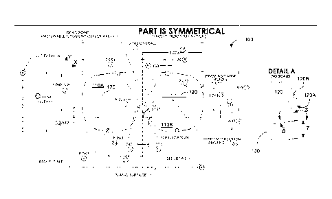
[0011] Fig. 1 illustrates an implementation 100 of the optical filter
system of the present
invention, which is shown formatted as goggles in which each of the lenses
110A, 110B includes a
spectral optical filter having a pass-band characterized by a central
wavelength. The spectral
characteristic of the lenses 110A, 110B is substantially the same across the
lenses within their
bounds. The lenses can be made of glass or a flexible plastic sheet. In the
latter example, the
typical thickness of the lenses is about 0.05 inches. Due to the parameters of
the spectral
transmission, the lenses are perceived by the user as optically transparent
elements the color of
which is substantially the same at any point within the bounds of the lenses.
It is notable that,
according to the idea of the invention, both the spectral pass-band of a
spectral filter of the
embodiment and the central wavelength of such pass-band are judiciously
defined in operational
correspondence with the spectral characteristics of at least one of the two
radiant objects of the
embodiment, as discussed below.
3
CA 02974822 2017-07-24
WO 2016/123234 PCT/US2016/015152
[00121 Coordination of Spectral Characteristics of Optical System and
Auxiliary Tools.
[00131 Figs. 5, 6, and 7 illustrate embodiments of various radiant objects
according to the
idea of the invention. The term radiant as used in this disclosure refers to
either the active quality of
emitting rays of light or a passive characteristic of being bright and/or
shiny. As shown in Fig. 5,
for example, the radiant object includes balls 500 (or, alternatively, radiant
elements shaped
differently) that are colored (by pigmentation, for example) in strict
correlation with the spectral
pass-band of the optical filter(s) of the invention. Specifically, the
coloration of at least one of the
elements 500 is chosen within the spectral band chosen such as to define, in
reflection of ambient
light incident onto the radiant element, a color that is complementary to the
color defined by the
spectral pass-band of the optical filter of the invention. Complementary (or
opposite) colors as used
in this disclosure are pairs of colors which, when combined, cancel each other
out. This means that
when a given radiant object that is colored in a fashion complementary to the
spectral characteristic
of the optical filter of the invention is viewed through such filter, the
radiant object is perceived as
black. As shown in Fig. 5, the balls include two black balls 510, two red
balls 520, and two orange
balls 530.
[00141 The units having complimentary colors, when placed next to each
other, create the
strongest contrast for those particular two colors. In one non-limiting
example, the embodiment of
the system of the invention includes optical filters providing high level of
transmission in the green
portion of the spectrum and blocking light in the red portion of the spectrum,
while at least one
radiant object is colored red. Other pairs of complementary colored can be
used such as yellow and
violet, or blue and orange, for example.
[00151 In a related embodiment, the radiant object may include a source
generating light
within the spectral band that is complementary to the spectral band of the
optical filter(s) of Fig. 1.
In reference to Figs. 6 and 7, the sources of light can be configured to
generate light continuously or
in a modulated (flashing) fashion. For example, sources of light may include a
pen 610 containing
an LED 610 that is wired to operate in a flashing regime or in a continuous
regime, at user's
discretion, a laser pointer 710 including one or more laser diodes at least
one of which generates
light within the band complimentary to the pass-band of the optical filter
110A, 110B, or just a
simple light source 620 (an LED, for example) configured to operate either
continuously or
flashing. The source of light can be part of a digitally projected video
image, wherein certain pixels
or portions of the image can radiate light within the appropriate
complementary spectral band.
4
CA 02974822 2017-07-24
WO 2016/123234 PCT/US2016/015152
[0016] An example of one operationally sufficient spectral characteristic
200 of the optical
filter(s) of the invention is schematically presented in Fig. 2A with
indication of relative
coordination of the parameters ().5, AF), which define the absorption of
optical filters 110A, 110B,
and the wavelength ARthat is associated with the color of a radiant object.
The color defined by the
pass-band AAR and/or the wavelength A is complementary to that associated with
A,R. It is
appreciated that in practice, when an optical filter of the invention exhibits
sufficiently large (for
example, several-fold) difference between the transmission of light at
complementary wavelengths,
the operational goal of using such optical filters in an embodiment of the
invention will be achieved.
A measured spectral characteristic 220 of the optical filters 110A, 110B is
shown in Fig. 2B. While
not necessarily optimized, the spectral curve 220 illustrates that the level
of transmission in the
green portion of the visible spectrum is on the order of magnitude (or at
least several times) smaller
than that in the red portion of the visible spectrum. In practice, such
optical filter(s) sufficiently
block transmission of red light from the radiant objects. Fig. 2C illustrates
an image of white field
viewed as green in transmission through an embodiment of the optical filter.
[0017] Spatial Characteristics of Optical Filter(s).
[0018] In addition to pre-determined spectral pass-band of the filters
110A, 110B, each of
the filters contains an additional spatial pattern at a body of the optical
filter. The spatial pattern is
judiciously configured to define different phase delays for two different
light beams that propagate
through the optical filter at different points.
[0019] Referring again to Fig. 1, anon-limiting example of such pattern is
shown in inset as
a prismatic surface-relief structure 120 defined at the surface of each of the
filters 110A, 110B by
rulings 120A (which may be spatially periodic or non-periodic). As shown, the
prismatic structure
is periodic and includes linear rulings / grooves separated by the prismatic
elements 120B that
extend, substantially, across the whole clear aperture of the filters 110A,
110B. While the direction
in which the prismatic structures 120B (and the rulings 120A) are extended
substantially coincides
with a horizontal direction as defined by the use of the goggles 100 (and
shown as the x-axis in Fig.
1), it is appreciated that a related embodiment with certain angular deviation
between the direction
of the rulings 120A and the x-axis, possible in practice, is still within the
scope of the invention. An
example of such deviation is indicated in Fig. 1 as +/- 1 degree, but in
practice can be several
degrees, for example +/- 5 degrees or even within the range of +/- 10 degrees.
CA 02974822 2017-07-24
WO 2016/123234 PCT/US2016/015152
[0020] The spatial pattern 120 of the optical filters 110A, 110B in the
example of Fig. 1 is
defined by the period T, the slope angle S (an angle between a facet of an
element of the prismatic
structure with respect to the planar surface 130 of the optical filter 110A,
110B), the draft angle D,
and the height h. Fig. 3 provides a schematic illustration of a single
prismatic element 120B of the
prismatic structure 120, which has a refractive index n. In one example, the
period T is about 150
microns, the slope angle S is about 19 , and the draft angle D is minimized
(the residual draft angle
may be about a couple of degrees or so, which is defined by the process of
manufacture of the
prismatic structure 120). A person of ordinary skill in the art will
appreciate that the degree of
uncertainty in specifying these values denoted is determined, on the one hand,
at least by the
practical limitation of equipment used to fabricate the spatial pattern and,
on the other hand, by a
need to satisfy the "stealthy" appearance of the pattern to the naked eye of
the user. For example, it
may be preferred that the period T of the pattern is chosen such as to not
produce any visually
perceivable optical effects (such as the optical diffraction effect) when
viewed by the user. At the
same time, the period T should be such as to be not easily discernible.
Accordingly, in one
embodiment the value of T could exceed the wavelength of visible light while
being smaller than,
for example, a millimeter.
[0021] In reference to Fig. 3, for a collimated beam of light Li incident
nolinally onto a
plano-prismatic optic such as the element 120B, the angle of deviation A of
the throughput light
beam L2 from the direction of incidence may be calculated as a function of the
slope angle S. The
dependence of angle A on the slope angle differs depending on whether the
collimated beam
impinges from the ambient on the planar surface 130 of the optical filter 110A
(as shown in Fig. 3)
or on the surface of the prismatic structure (in other words, on the
orientation of the optical filter
with respect to incident light). In the case of Fig. 3, in which the planar
side 130 of the optical filter
110A, 110B faces in input light LL the value of the angle of deviation A is
defined as
[0022] A = arcsin [¨n + .\/1 ¨ (n2 ¨ 1)q]}(1)
q2+1
[0023] where q = tan (5). Fig. 4A illustrates this dependence of the angle
A on the angle
S for two materials (acrylic, I; and polycarbonate, II). In the case in which
light Li from the
ambient is incident onto the prismatic surface of the optical filter 110
(which, in the coordinates of
Fig. 1 corresponds to the surface relief structure 120 being disposed at the
surface of the lenses
facing the user, in operation), the deviation angle can be shown to follow
6
CA 02974822 2017-07-24
WO 2016/123234 PCT/US2016/015152
q2 1 [0024] A = arcsinfq-:1+1+ \ 1,12+1+ (q2+in2 ¨ 1)11 (2)
[0025] Fig. 4B illustrates this dependence of the angle A on the angle S
for two materials
(acrylic, I; and polycarbonate, II).
[0026] As follows from Figs. 1 and 3, the prismatic structure 120 is
configured to cause the
user wearing the optical filter(s) 110A, 110B in front of his eyes to change
his line of sight and look
upwardly (into the beam L2) when perceiving the ambient environment through
the optical filters,
which correlates with behavior of a person under the influence of recreational
marijuana and/or
correlates with a slight sensation of impairment of such person. Depending on
the desired strength
of this effect (i.e., depending on the desired, angle of deviation A), the
slope angle S may be
changed within the appropriate limits the examples of which are illustrated in
Figs. 4A, 4B.
[0027] It is appreciated that, in a related embodiment, the pattern 120 can
be formed in the
body of the optical filters as a phase-based element (for example, by
structuring the bodies of the
optical filters to contain an array of linear bands or areas the refractive
index of which differs from
that of the surrounding portion(s) of the filters 110A, 110B).
[0028] In contradistinction with optical filters of related art (which
feature translucent
filters), the embodiments of the present invention include filters that are
optically-transparent and
have a spectral characteristic (such as a pass-band, for example) that is
invariable as a function of
the position across the filter. Optical transparency is known to be the
physical property of allowing
light to pass through the material without being scattered. On a macroscopic
scale (one where the
dimensions investigated are much larger than the wavelength of light in
question), Snell's law is
followed. To the contrary, the property of translucency allows light to pass
through without
following (again, on the macroscopic scale) Snell's law; the photons can be
scattered at either of the
two interfaces where there is a change in index of refraction, or internally.
In other words, a
translucent medium allows the transport of light while a transparent medium
not only allows the
transport of light but allows for image formation. As discussed above,
embodiments of the present
invention also contain a physical pattern (such as a surface prismatic
structure 120 or its phase-
structure analog formed by the variation of the refraction index) that is a
linear function of a spatial
coordinate along a surface of the filter, judiciously configured to ensure
that light incident onto the
optical filter from the ambient is deviated from its original direction of
propagation and re-directed
7
CA 02974822 2017-07-24
WO 2016/123234 PCT/US2016/015152
in the same new direction regardless of a point of incidence of the ambient
light onto the filter.
Such physical pattern is extended along a straight line.
[0029] Additional System Components.
[0030] An embodiment of the invention may additionally include a maze 800
drawn on a
pad (Fig. 8), different portions of which may have complementary colors
associated with the
spectral characteristics of the optical filters and used for simulating of
impairment of executive
function; a video (for example, on a tangible non-transitory storage medium
such as a flash-drive
720, Fig. 7) containing various driving scenes used for illustration of the
road condition to the user
and simulation of the impairment of the reaction time, visual perception, and
response; and/or a
grid-mat 900 (Fig. 9) with a road pattern on it that is used, in conjunction
with a least one of the
radiant objects 910, for simulation of the impairment of the effect of
marijuana on the short-term
memory of the user. Alternatively, the maze 800 can be provided on a surface
that permits reuse
after cleaning. The maze can be peimanently or semi-permanently provided on
the surface. For
example, the maze 800 can be printed onto a reusable whiteboard surface, which
can itself be
portable or fixed, such as to a wall or table.
[0031] Embodiments of Method.
[0032] Example I. The use of a system for simulating a distorted perception
of visual
information and missing important visual clues.
[0033] According to an embodiment of the method of the invention, the user
is caused to
catch, one at a time, several radiant objects 500 each of which is shielded
from his view until tossed
to the user. The chosen radiant objects reflect light of the ambient in
different spectral bands, with
at least one of the objects being characterized by a color that is
complimentary to the color defined
by the pass-band of the optical filters of the invention. For example, when
the pass-band of the
optical filters of the invention is defined in the green portion of the
spectrum, some of the radiant
objects 500 may be red, some orange, and some black. During the process, the
task is defined as
catching only the black objects and avoiding the red and the orange ones. The
correctness of the
choices in determining the color of the objects to be caught made by the user
who perceives the
environment with a naked eye is compared with the results of a similar
experiment when the user is
asked to look at the ambient environment through the optical filters 110A,
110B (which may be
used in the goggles 100). It is appreciated that the user cannot correctly
discern the color of the
objects 500 through the optical filters 110A, 110B, as the red balls are
perceived through the green
8
CA 02974822 2017-07-24
WO 2016/123234 PCT/US2016/015152
filters as being black, and therefore makes more mistakes in trying to catch
only the black balls.
This test stimulates the cognitive impairment of not recognizing and
responding to sensory input
that results from recreational marijuana use.
[0034] Example 2: The use of a system for simulating a disruption of
executive functions for
example, short-term memory and decision-making skills).
[0035] This embodiment of the invention illustrates the impact of this
impairment on an
attempt to solve the maze 800. At the first step, the maze is shown to the
user in the video or
demonstrated otherwise. The user is then asked to pick a radiant object
including a flashing source
of light (such as a pen 610 of Fig. 6) and to complete the maze provided on
paper, optionally
recording the time it takes to complete the maze. Once finished, the user is
asked to complete the
maze while observing it through the goggles (or just the optical filters) of
the invention. The results
of these two experiments may be compared and contrasted, during the
discussion, to identify
confusion, hesitation, and difficulty remembering decisions for completing the
maze that have been
made prior to wearing the goggles.
[0036] Example 3: The use of a system .for simulating a loss attention and
distorted
perception of visual information.
[0037] The use of marijuana filters the FOV from which the consumer draws
and uses
information, especially while driving, while there is nothing physically wrong
with the user's ability
to see. At the same time, the consumption of marijuana causes the consumer to
focus more on only
one sensory input at the expense of other sensory inputs. For example, the
user concentrates harder
of what is seen in front of him and pays less attention to hearing or seeing
at the periphery of his
FOV.
[0038] According to this embodiment of the invention, the object of the
test includes a
typical driving scenario and items typically seen in a driving situation and
is demonstrated to the
user on video. The dual laser pointer (such as the pointer 710 containing the
red and green laser
sources, for example) is used to point from object to object in the driving
scene with the purpose of
identifying them verbally. The objects in the driving scene are highlighted
with the dual laser
pointer randomly and with light beams that are randomly switched from red to
green. Following this
initialization step, the user is caused to look at the ambient through the
optical filters (for example,
wear the goggles) configured according to the idea of the invention and has to
identify the objects
pointed to in the similar fashion. In the latter case, the user does not
perceive those objects that are
9
CA 02974822 2017-07-24
WO 2016/123234 PCT/US2016/015152
pointed to with a red laser beam when wearing the green optical filters due to
the mutual
cancellation of the complimentary colors, which demonstrates how being unaware
of subtle
environment changes can lead to being unprepared for a sudden traffic event.
[0039] Example 4: The use of a system for simulating a loss of reaction
time, attention, and
a distorted perception of visual information.
[0040] According to an embodiment of the invention, the initialization of
this activity is
similar to that in Example 3. The driving scenario video is shown to user(s)
on the screen. Some of
the users are made to look at the ambient environment through the optical
filters (for example, wear
the goggles 100), while others are observing the scene with a naked eye.
Participants wearing the
goggles of the invention are asked to use the green laser pointer to point at
the brake button on the
screen to simulate "hitting the brake" each time they perceive that the
traffic conditions require
braking or covering the brake. Participants not wearing the goggles are asked
to use red laser
pointers to point at the brake button each time they perceive that the traffic
conditions require
braking or covering the brake. The red laser spots on the screen will not be
seen by the
participant(s) wearing the goggles. The results of both tests and, in
particular, the difference in
reaction time required for the two groups of participant to react to changes
in the traffic conditions
are then analyzed to identify missed, delayed, or incorrect braking in the
traffic conditions done by a
given participant.
[0041] Example 5: The use of a system for simulating impairment of motor
skills, memory,
and decision making abilities.
[0042] According to an embodiment, the grid mat having a square pattern on
it is laid out
on the floor, and sources of light 620, 910 some of which are configured to
generate light in a
flashing / blinking fashion are positioned on the intersections of the square
pattern, as schematically
shown in Fig. 9. Initially, the user is given time to study the grid with a
naked eye and to memorize
the intersections with the blinking activity light on. At the next step, the
user is asked to put the
goggles on and walk the grid identifying, through the optical filters of the
invention, which lights
are blinking and which are not. The spectrum of light generated by the
blinking sources of light
corresponds to color that is substantially complementary to the color defined
by the spectral pass-
band of the optical filters of the invention. Comparison of the results of the
identification of the
blinking lights on the grid through the optical filers of the invention with
those perceived with the
naked eye demonstrate the reduced confidence in remembering the lights as
being on or off before
CA 02974822 2017-07-24
WO 2016/123234 PCT/US2016/015152
the user puts the goggles on. The results are discussed with the user to
illustrate the impact that
short-term memory lapses can have in various situations where the mobility of
a person is affected
by the use of marijuana (such as driving, walking, biking, for example).
[0043] In accordance with examples of embodiment, system and method for
simulating the
impairment caused by consumption of marijuana have been described. These
examples can be
appropriately modified without changing the scope of the invention. While
specific values chosen
for an embodiment of the system are recited, in reference to Figs. 1, 2A, 2B,
3, 4A, 4B it is to be
understood that, within the scope of the invention, the values of all of
parameters may vary over
wide ranges to suit varying applications. Disclosed aspects, or portions of
these aspects, may be
combined in ways not listed above. Accordingly, the invention should not be
viewed as being
limited to the disclosed embodiment(s)
11