Note: Descriptions are shown in the official language in which they were submitted.
CA 02975399 2017-07-28
WO 2016/122334 PCT/N02016/050015
1
Offshore material handling system and material handling method
The present invention relates to an offshore material handling system
including
a crane carrying vessel, a fixed installation structure projecting above the
sea
level, which installation structure includes a material handling distribution
system on board the installation structure.
The present invention also relates to a method for offshore lifting operations
between a crane carrying vessel and a fixed offshore installation structure
projecting above the sea level, which installation structure includes a
material
handling system onboard the installation structure.
From WO 2012/007002, a system and method for movement of payloads
between a service vessel and an offshore wind turbine by use of a conveyor
ramp, is known. However, on page 1 of this publication they partly tell away
from the subject matter of the present patent application by the following
statement (quotation): The lifting of components directly off a service vessel
alongside the turbine requires that the lifting crane have a rating which is
significantly in excess of that required to lift the same component in an
onshore
environment. The movement of the component as a result of the movement of
the vessel in response to the action of waves, current and wind can
significantly
increase the loading on the crane depending on the particular conditions".
From US patent no. 8,523,490 B2, temporary platforms and methods of
securing such platforms to an offshore structure, is shown.
The present concept has been developed primarily for use with unmanned
wellhead platforms without having an offshore crane installed onboard. An
example of such platform is the "Subsea on Stick" (SoS) platform designed by
the applicant. This was developed to simplify logistics for load handling at
sea
for lifting materials to and from an offshore installation by use of offshore
crane
at vessel, and is also especially prepared for handling well intervention
equipment, and to minimize the need for maintenance and certification of
lifting
CA 02975399 2017-07-28
WO 2016/122334
PCT/N02016/050015
2
equipment offshore. Another purpose was to expand options with regards to
performing operational work on unmanned wellhead platforms, including other
fixed installations having the same requirements to load handling without
having
an offshore crane installed onboard.
The present invention has the effect that the requirements to the crane can be
transferred from an installation to a vessel.
Offshore lifts on fixed installations are subject to strict requirements
regarding
type of crane, certification, maintenance, and operations. The use of offshore
cranes on fixed installations results in that a substantial need of man hours
are
necessary to carry out maintenance and offshore certification of the lifting
equipment. With an unmanned installation like the SoS the need for man hours
on board is substantially reduced.
This can be done by performing the offshore lifts by means of external
equipment and only perform internal material handling onboard the installation
with lifting appliances and equipment having reduced need for offshore
certification and only perform checks by their own personal with visual
control,
and reduced extent of work like less maintenance and simplified operation for
high degree of exploitation with personal possessing multifunction competence
etc.
Thus, the present platform/crane system is designed and used such that a
particular method leads to that an especially designed crane/offshore crane
onboard the installation is no longer needed to perform a complete load
handling. With the onboard lifting appliances, the respective loads are
distributed internally and thus there are no requirements to certified
offshore
crane onboard the installation, unmanned wellhead platform or SoS An
offshore crane is present on the vessel and this crane has all necessary
certifying for kay/onshore facility.
CA 02975399 2017-07-28
WO 2016/122334
PCT/N02016/050015
3
This method resolves several requirements to the regulations to be more
appropriate. In addition, for unmanned wellhead platforms, it will be possible
to
handle heavier equipment prepared for temporary location onboard to carry out
well intervention, for example.
Well intervention can simplest be explained in that the wells are maintained
in
order to produce more oil or gas for a longer period of time, which leads to
very
good economy when using unmanned wellhead platforms instead of subsea
installations, for example.
Said in a simple way, the handling of loads (standard load carriers,
especially
designed load carriers for well intervention and wireline operations, goods
and
materials) can be the decisive point weather to exploit a field or not with
unmanned wellhead platforms and one may therefore say that those having
resolved this, will have a great advantage relative to the competitors.
The challenge with resolving the concept has traditionally been that bigger
cranes have been designed, or made dependent of huge crane vessels or
specially designed crane vessels, to be able to lift equipment to a high level
or
on top of the installation. The reason why the lifts are getting high and
loading
areas are little accessible, is that structures, such as the load platforms,
are
subjected to severe sea stresses when close to the sea surface. This entails
consequences for the structure, not only locally, but can also influence on
entire
integrity of the installation. At the wave influenced zone the installation
structure
shall have as "clean" or "smooth" structures as possible. Also, if lifting to
a high
level or on top of the installation from a vessel, may lead to lifting
operations
into blind zones, which is not acceptable and may increase risk for incidents
above the acceptable.
Thus the basic idea according to the present invention was to provide a load
handling system of the introductory said kind, which system is distinguished
in
that the load handling system includes an independent platform structure for
CA 02975399 2017-07-28
WO 2016/122334
PCT/N02016/050015
4
temporary attachment on the installation structure and temporary use on the
installation structure for load transfer.
The platform structure is to be hung temporarily onto the installation
structure at
a level above sea so low that conventional service/supply vessels with
conventional heave compensated cranes can be used. In addition, the different
regulations worldwide in respect of visibility, control of the load,
requirements to
the cranes etc. are now resolved in a very simple way by the present concept.
In one embodiment of the present invention, the load handling distribution
system onboard the installation structure includes an onboard crane or lift
able
to elevate or lower a load from or to the independent platform structure.
The crane onboard could be of any suitable kind, such as a gantry crane or a
slewing crane.
The vessel may also be of any suitable kind of vessel, such as a supply vessel
or a service vessel.
The installation can be an unmanned wellhead platform, by the applicant also
termed a "Subsea on Stick" (SoS).
In one embodiment the independent platform structure can be a corner platform
structure.
According to the present invention, also a method of the introductory said
kind
is provided, which method comprises the following steps: a) the crane on the
crane carrying vessel brings an independent platform structure from the vessel
onto the installation structure for temporary use as a load station on the
installation structure, b) the crane on the crane carrying vessel brings a
load
from the vessel onto the independent platform structure, c) the load handling
distribution system brings the load to predetermined level of the installation
structure.
CA 02975399 2017-07-28
WO 2016/122334
PCT/N02016/050015
In addition, the method may include the following step: d) the load handling
distribution system brings a second load from the vessel onto the independent
platform structure and continues according to step c) above.
5
Further, the method may include the following step: e) the crane on the crane
carrying vessel releases and brings the independent platform structure back
from the installation structure onto the vessel.
According to the present invention also an independent platform structure for
temporary attachment to the installation structure and use on the installation
structure defined above is provided, which platform structure includes
attachment means in form of hooks or other fixation means to be attached or
hooked onto the installation structure at suitable installation structure,
such as
braces or beams adapted to thrust against the installation structure.
Further, the platform structure may include a ladder or gangway to enable
forming a walkway from the platform onto the installation structure.
Preferably, the platform structure and interface on the installation structure
is to
be standardized such that one and the same platform structure can be used on
several installation structures.
Example of embodiment
While the various aspects of the present invention has been described in
general terms above, a more detailed and non-limiting example of an
embodiment will be described in the following with reference to the drawings,
in
which:
Fig. 1 is a perspective view of the installation structure, the vessel with
offshore crane and the independent platform structure, and standard
load carrier;
CA 02975399 2017-07-28
WO 2016/122334
PCT/N02016/050015
6
Fig. 2 is a perspective view of the crane on vessel being used to lift the
independent platform structure from vessel for temporary attachment on
the installation structure;
Fig. 3 shows the independent platform structure attached to the installation
structure;
Fig. 4 shows lift between vessel and the installation structure;
Fig. 5 shows the independent platform structure attached to the installation
structure with standard load carrier ready for internal material handling;
Fig. 6 is perspective views of the installation structure with the independent
platform structure attached thereto, gantry crane for internal material
handling between the independent platform structure to landing area
ready to lift standard load carrier;
Fig. 7 show the top deck with gantry carne, ready for internal material
distribution of standard load carrier;
Fig. 8 shows an alternative crane structure onboard the installation
structure;
and
Fig. 9 shows in perspective view an alternative embodiment if the invention
showing a corner platform structure to be installed on a corner of the
installation structure.
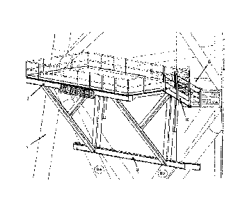
Reference is firstly made to fig. 6 Showing a perspective view of an offshore
installation structure 1 of a type called Subsea on Stick . The installation
structure 1 is made up as an open trusswork structure projecting above the
surface of the sea. A Gantry crane 2 is located on top of the installation
structure 1 and is straddling over a top deck of the installation structure 1.
The
Gantry crane 2 is moveable on rails back and forth, while a traverser carriage
with lifting gear and hook, is running traverse to such back and forth
direction, in
order to be able to put off loads at any point all over the top deck.
Fig. 3 shows the installation structure 1 according to fig. 6 with the detail
of the
independent detachable platform structure 3 attached to the installation
structure 1 some distance above the sea level. The platform structure 3
CA 02975399 2017-07-28
WO 2016/122334
PCT/N02016/050015
7
illustrated, is provided with two spaced apart heavy hooks designed to hook
onto a substantially horizontal truss bar on the installation structure 1.
Fig. 2 shows the various components of the system according to the invention.
The system includes a supply boat 4 having a crane 5 onboard, in addition to
the above described installation structure 1 and the detachable independent
platform structure 3.
Fig. 1 shows a first step of performing the method steps according to the
invention. A hook 6 on the crane 5 is connected to the platform structure 3
lifted
off the boat deck at this stage. The hook 6 is more clearly shown in fig. 2
when
the platform structure 3 is lifted a distance above the deck of the supply
boat 4
ready for the transfer over the boat rail.
Fig. 2 shows the platform structure 3 after having been swung out over the
rail
and to the proximity of the installation structure 1. The next and last step
is
shown in fig. 2 where the platform structure 3 is hooked onto a horizontal
truss
beam 6 on the installation structure 1.
In Fig. 3 the platform structure 3 is securely attached to the installation
structure
1. The lower part of the platform 3 is resting against two respective inclined
truss beams 8a, 8b by means of a substantially horizontal thrust bar 9 on the
platform 3 structure. A ladder or ramp gangway 10 is shown to the right hand
side on the platform structure 3. As shown in fig. 3, the gangway 10 can be
pivoted to establish a walkway over to a staircase structure on the
installation
structure 1.
Preferably, the platform structure 3 and interface on the installation
structure 1
is to be standardized such that one and the same platform structure 3 can be
used on several installation structures 1.
CA 02975399 2017-07-28
WO 2016/122334
PCT/N02016/050015
8
Next step is to bring a load 11, or several loads, from the supply vessel 4
over
to the platform structure 3, as illustrated in fig. 1 and 4. This is done in a
per se
conventional manner.
Fig. 4-7 shows sequential internal transportation steps on board the
installation
structure 1 from the platform structure 3 to the top deck of the installation
structure 1. This is done by means of the Gantry crane 2.
Fig. 8 shows a situation where a number of loads have been transferred to the
top deck of the installation structure 1 by repeated transportation steps as
indicated by fig. 4 to 7. Also an intervention equipment 12, or tool, has been
installed and erected on the top deck of the installation structure 1 with
alternative crane structure onboard the installation structure 1.
Fig. 9 shows in perspective view an alternative embodiment if the invention
showing a corner platform structure 3A to be installed at a corner of the
installation structure 1.
As in the Fig. 3 embodiment, the independent and detachable corner platform
structure 3A is attached to the installation structure 1 some distance above
the
sea level. The platform structure 3A is provided with two spaced apart heavy
hooks 3C designed to hook onto respective horizontal truss bars 6, which
respective horizontal truss bars 6 are located on respective sides of the
installation 1.
In Fig. 9, the platform structure 3A is securely attached to the installation
structure 1. The lower part 3B of the platform structure 3A is resting against
a
corner column extending in an inclined direction from the sea and to the top
of
the installation structure 1. A ladder or ramp gangway (not shown) can be
installed in order to establish a walkway over to a staircase structure on the
installation structure 1.