Note: Descriptions are shown in the official language in which they were submitted.
CA 02975539 2017-08-01
- 1 -
CUTTING TOOL APPARATUS
The invention relates to a cutting tool apparatus comprising a tool head
rotatingly drivable about an axis of rotation, which tool head has a tool
slide
adjustable along an adjustment axis and an electrical measuring device for
detecting an adjustment path of the tool slide, and comprising an external
display device which is mechanically and electrically releasably connectable
to
the tool head and has a display unit for displaying the adjustment path of the
tool slide.
From the publication EP 2 493 647 B1 there is known a cutting tool in the form
of a precision turning tool, with the aid of which mainly bores with narrow
tolerances are machined. The tool head of the precision turning tool can be
clamped into the spindle of a machine tool and set in rotation about an axis
of
rotation by means of the machine tool. The tool head has a tool slide, on
which a cutting plate holder is mountable. A cutting plate can be secured on
the cutting plate holder in order to machine a bore in a material-removing
manner. In order to set a desired turning or boring radius, the tool slide can
be adjusted radially with respect to the axis of rotation of the tool body
with
the aid of a separate adjusting tool, for example a polygonal tool. The
adjustment path of the tool slide can be detected by means of a measuring
device of the precision turning tool and displayed to the user on a display
unit.
The display unit is integrated into the tool head, so that the user when
adjusting the tool slide can read the adjustment path in a simple manner on
the display unit. For tool heads with a relatively large diameter, such a
configuration has proved successful. However, if the tool head has only a
small
design, the size of the display unit is limited and the adjustment path can no
longer be displayed in an easily readable manner.
From EP 1 758 710 B2 there is known a cutting tool apparatus in which the
display device is not integrated into the tool head but into the separate
adjusting tool, with the aid of which the tool slide can be adjusted. The
CA 02975539 2017-08-01
- 2 -
adjustment path of the tool slide can be detected by means of the measuring
device of the tool head, and an electrical connection can be established
between the measuring device and the display device of the adjusting tool by
means of contact elements arranged laterally on the tool head.
From the publication DE 10 2009 017 094 Al there is known a cutting tool
apparatus in which measurement information can be transmitted from the
measuring device of the tool head by radio to an external display device. The
display device has a permanent magnet which serves as a holding device and
makes it possible to fix the external display device on a magnetisable metal
body, for example on the machine tool. The display device can thereby be
positioned in a place ergonomically favourable for an operator. However, metal
chips frequently collect on the permanent magnet and this makes the handling
of the cutting tool apparatus difficult.
There are also known cutting tool apparatuses in which the external display
device is electrically connected to the measuring device of the tool head via
a
cable. For this purpose, a magnetic plug can be placed on a complementarily
configured interface of the tool head, in order to transmit measurement
information from the measuring device via the cable to the external display
device. The user has the possibility to hold the external display device with
one hand and adjust the tool slide with his other hand by means of the
adjusting tool. The disadvantage of such a configuration is that the user
cannot have both hands free to be able to carry out a precise adjustment of
the tool slide and of the cutting plate holder.
The object of the present invention is to further develop a cutting tool
apparatus of the type mentioned at the outset such that it has a simplified
handling.
This object is achieved in accordance with the invention in a cutting tool
apparatus of the type in question in that the display device is mechanically
securable on the stationary tool head in order to set the tool slide and is
CA 02975539 2017-08-01
- 3 -
automatically releasable from the tool head if a predetermined rotational
acceleration of the tool head is exceeded.
To set the tool slide the external display device of the cutting tool
apparatus
according to the invention is mechanically secured on the tool head, and in so
doing the tool head does not perform a rotational movement but is stationary.
The user has both hands free for adjusting the tool slide, so that he can
adjust
the tool slide very precisely. Since the external display device is
mechanically
securable on the stationary tool head, the user can read the adjustment path
displayed on the display unit in a simple manner when adjusting the tool
slide.
The size of the display unit is not predetermined by the constructional size
of
the tool head, but can be chosen of sufficient size, irrespective of the tool
head, so that the displayed adjustment path can be easily read. The
mechanical securing of the external display device on the tool head ensures
that the display device is not unintentionally released from the tool head on
the setting operation of the tool slide. Nevertheless, the securing on the
tool
head involves the risk that the user may forget to remove the display device
from the tool head before setting the tool head in rotation. This could result
in
the display device rotating together with the tool head and being hurled away
from the latter in the radial direction. In order to counteract this danger,
the
display device in the cutting tool apparatus according to the invention is
automatically releasable from the tool head as soon as the latter exceeds a
predetermined rotational acceleration. When the tool head is set in rotation
to
machine a workpiece, it is typically subjected to high rotational
accelerations
in order to reach its nominal rotational speed within a short time. The
critical
value of the rotational acceleration, on the exceeding of which the display
device is automatically released from the tool head, can be chosen to be very
small. This ensures that the display device, inadvertently left on the tool
head
when the tool head is set in rotation, is automatically released from the tool
head even before the latter has reached a high rotational speed, and this in
turn has the advantage that the display device can at most be slightly hurled
in the radial direction by the rotating tool head, but rather falls more or
less
vertically downwards owing to its weight force if the tool head exceeds the
CA 02975539 2017-08-01
- 4 -
predetermined rotational acceleration. It is thereby ensured that the display
device being automatically released from the tool head does not constitute a
risk of injury to the user if he forgets to release the display device from
the
tool head when the tool head is set in rotation.
If the tool head with the display device mechanically secured thereon is
inadvertently set in rotation, the tool head undergoes a high rotational
acceleration. According to the invention, it has been found that the
rotational
acceleration of the tool head can by utilised for automatically releasing the
display device from the tool head. For this purpose, it is advantageous when
the display device is layable onto a lateral surface of the tool head,
preferably
in a joining direction orientated obliquely or perpendicularly to the axis of
rotation. The display device can thus be positioned laterally on the tool
head.
If the tool head with the display device held thereon is inadvertently set in
rotation about its axis of rotation to machine a workpiece, the display device
lying on the outside of the tool head undergoes considerable tilting moments
owing to its inertia, which are dependent on the rotational acceleration of
the
tool head. The greater the rotational acceleration is, the greater are also
the
tilting moments acting in the circumferential direction of the tool head on
the
display device. The mechanical and electrical connection of the display device
to the tool head can be configured in such a manner that the display device is
automatically released from the tool head under the effect of a tilting moment
of a predetermined size acting in the circumferential direction of the tool
head.
It is favourable when the tool head has a cylindrical lateral surface and the
display device has a plane rear side, with which it contacts the cylindrical
lateral surface linearly. On both sides of the linear contact region, the
display
device thus protrudes with its rear side from the tool head. This facilitates
the
automatic release of the display device from the tool head, as soon as the
latter exceeds a predetermined rotational acceleration.
Provision may be made for the display device to be releasably latchable to the
stationary tool head. For this purpose, latching elements cooperating with one
CA 02975539 2017-08-01
- 5 -
another in the sense of a latching connection may be used, which are arranged
on the display device and on the tool head, the latching connection being
automatically releasable as soon as the tool head exceeds a predetermined
rotational acceleration. The latching elements may, for example, engage in
one another in a spring-mounted manner. It is favourable when the spring
force of the latching elements is predeterminable. This makes it possible to
predetermine the spring force in the manufacturer's works of the display
device in such a manner that the display device is automatically released from
the tool head if a predetermined, relatively low rotational acceleration of
the
3.0 tool head is exceeded.
In a preferred configuration of the invention, the display device has at least
one holding member, the tool head being subjectable to a predeterminable
holding force by the at least one holding member. Owing to predetermining of
the holding force by the manufacturer, it can be ensured in a constructionally
simple manner that the display device is automatically released from the tool
head if the latter exceeds a predetermined rotational acceleration on the
setting in rotation.
It is particularly advantageous when the at least one holding member has a
setting mechanism for setting the holding force exerted on the tool head by
the holding member. The setting mechanism may, for example, be actuated in
the manufacturer's works of the display device for predetermining a specific
holding force which is exerted on the tool head by the holding member, in
order on the one hand to ensure that the display device is mechanically
securable on the stationary tool head, and on the other hand to ensure that
the display device is automatically released from the tool head if the latter
exceeds a predetermined rotational acceleration.
The setting mechanism may, for example, have a setting screw. This facilitates
the setting of the holding force.
CA 02975539 2017-08-01
- 6 -
It is particularly favourable when the at least one holding member is able to
be
mechanically brought into engagement with the tool head. The holding
member is thus engageable and by the engagement of the holding member
with the tool head, it is possible to ensure in a constructionally simple
manner
that the display device is securable in a mechanically loadable manner on the
stationary tool head and is releasable from the tool head if a predetermined
rotational acceleration is exceeded.
It is of particular advantage when the display device has two holding members
which are insertable into two holding recesses arranged at a distance from one
another in the direction of rotation of the tool head. In such a configuration
the tool head has two holding recesses which are arranged at a distance from
one another in the direction of rotation of the tool head and into each of
which
a holding member of the display device can be inserted.
Favourably the holding member inserted into a holding recess exerts a
predeterminable holding force on a wall of the holding recess.
The holding recesses are favourably open at their outer sides facing away from
one another. The holding recesses may, for example, be formed open on one
side. This facilitates the release of the holding members from the holding
recesses, as soon as the tool head exceeds a predetermined rotational
acceleration.
The holding recesses may, for example, each have a plane bottom wall and a
side wall U-shaped in the plan view of the holding recesses. The side walls
may each have two straight end sections which lie opposite one another and
are connected to one another via a curved middle section.
At their mutually facing inner sides the holding recesses have, in an
advantageous embodiment of the invention, each at least one latching
element which cooperates with an associated latching element of the holding
member insertable into the holding recess.
CA 02975539 2017-08-01
- 7 -
Provision may be made, for example, for a latching indentation to be arranged
in each case at the mutually facing inner sides of the holding recesses, into
which latching indentation a latching projection of the holding members
latches. In this case it is of advantage when the latching projections
penetrating into the latching indentations are subjectable to a
predeterminable
spring force in the direction of the latching indentations. The spring force
is
favourably settable by means of a setting mechanism of the holding members.
It is favourable when the holding members form a form closure with the
holding recesses. By means of the form closure it can be ensured in a
constructionally simple manner that the display device is automatically
released from the tool head only when the tool head exceeds a predetermined
rotational acceleration. In particular it can be ensured by the form closure
that
the external display device is not unintentionally released from the
stationary
tool head.
In an advantageous configuration of the invention, the holding members
receive between them a holding section of the tool head extending over an
angular region of less than 180 in the direction of rotation of the tool
head.
The two holding members can clamp the holding section of the tool head
between them and thereby mechanically secure the display device on the
stationary tool head.
It is favourable when the holding section extends over an angular region of
less than 90 in the direction of rotation of the tool head.
In a preferred configuration of the invention, the holding members have
spring-mounted pressure pieces lying opposite one another. By means of the
spring-mounted pressure pieces, a holding force can be exerted on the tool
head by the holding members.
CA 02975539 2017-08-01
- 8 -
The spring-mounted pressure pieces are favourably aligned flush with one
another.
Provision may be made for the pressure pieces to each have a pressure body
which is subjectable to a spring force by a compression spring, the spring
forces of the two pressure pieces being directed opposite one another. The
spring forces enable the external display device to be fixed on the stationary
tool head by the pressure bodies, subjected to the spring forces, clamping a
holding section of the tool head between them, which holding section extends
over an angular region of less than 1800 in the direction of rotation of the
tool
head.
It is of advantage when the distance between the two pressure pieces is
variable. This makes it possible to position the pressure pieces at a smaller
or
larger distance from one another and thereby set the holding forces exerted
by the pressure pieces on the holding section of the tool head lying between
them.
In a preferred configuration of the invention, the holding members each have
a guide part in which a pressure piece is arranged. Provision may be made, for
example, for the pressure pieces each to be screwed into a guide part. For
this
purpose, the pressure pieces may have an external thread which engages with
an internal thread of a guide part. The guide parts may be configured in the
manner of a sleeve.
The holding members are favourably configured as projections which project
from a rear side of the display device facing the tool head. Preferably, the
rear
side of the display device lies on a lateral surface of the tool head. The
holding
members which each form a projection can be arranged symmetrically at a
distance from the region on which the rear side lies and can penetrate into
associated holding recesses of the tool head.
CA 02975539 2017-08-01
- 9 -
To establish an electrical connection between the measuring device of the tool
head and the display unit of the display device, the display device and the
tool
head have, in an advantageous configuration of the invention, electrical
contact elements associated with one another.
The contact elements of the display device and/or of the tool head can be of
spring-loaded form, so that the contact elements of the display device and of
the tool head are pressed against one another when the display device is
mechanically and electrically held on the stationary tool head.
Preferably, the contact elements of the display device are arranged axially
offset from the holding members, with respect to the axis of rotation of the
tool head. In such a configuration, the contact elements of the tool head
occupy a position axially offset from the holding region of the tool head
which
extends between the two holding recesses, into which the holding members
are insertable.
Preferably, the tool head has a contact recess, in which the contact elements
of the tool head are arranged. The contact recess forms an indentation which
is preferably arranged on a cylindrical lateral surface of the tool head and
which receives the contact elements of the tool head. The contact elements of
the display device can penetrate into the contact recess and electrically and
mechanically contact the contact elements of the tool head which are arranged
there.
As mentioned at the outset, the tool head may have a small constructional
size. In particular, provision may be made for the diameter of the tool head
to
be at most 20 mm, in particular 19 mm. By the use of the external display
device the user can, despite the relatively small constructional size of the
tool
head, be provided with an easily readable display unit which enables the user
to reliably adjust the tool slide and with the latter also the cutting plate
holder
and the cutting plate secured thereon.
CA 02975539 2017-08-01
- 10 -
The following description of an advantageous embodiment of the invention
serves, in conjunction with the drawing, for more detailed explanation. In the
drawing:
Figure 1: shows a perspective illustration of a cutting tool apparatus
having a tool head and an external display device mounted
laterally on the tool head;
Figure 2: shows a side view of the cutting tool apparatus in the
direction
of arrow A from Figure 1;
Figure 3: shows a side view of the cutting tool apparatus in the
direction
of arrow B from Figure 1;
Figure 4: shows a schematic sectional view of the cutting tool apparatus
along the line 4-4 in Figure 3;
Figure 5: shows a perspective illustration of the cutting tool apparatus
from Figure 1 in the direction of a front side of the external
display device, the display device being at a distance from the
tool head;
Figure 6: shows a perspective illustration of the cutting tool device
from
Figure 1 in the direction of a rear side of the external display
device, the display device being at a distance from the tool
head, and
Figure 7: shows a perspective illustration of the tool head of the
cutting
tool apparatus from Figure 1.
An advantageous embodiment of a cutting tool apparatus according to the
invention is illustrated schematically in the drawing and designated as a
whole
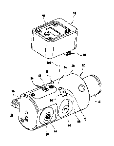
by the reference symbol 10. It comprises a tool head 12 which is rotatingly
CA 02975539 2017-08-01
11 -
drivable about an axis of rotation 14, and an external display device 16. The
display device is laterally layable onto a lateral surface 18 of the tool head
and
mechanically securable on the tool head 12, provided that the tool head 12 is
not performing a rotational movement but is stationary. When the tool head
12 is set in rotation about the axis of rotation 14, the display device 16 is
automatically released from the tool head 12, as soon as the latter exceeds a
predetermined, relatively low rotational acceleration. This is explained in
more
detail below.
As becomes clear in particular from Figure 2, the tool head 12 has a shank 15
which can be clamped into a spindle of a machine tool. Furthermore, the tool
head has a front recess 20 and a rear recess 22 which are each orientated
perpendicularly to the axis of rotation 14. In the front recess 20, a tool
slide
24 is displaceably mounted in a known manner, which tool slide can be
adjusted along an adjustment axis 26. The adjustment axis 26 is orientated
perpendicularly to the axis of rotation 14. To adjust the tool slide 24, use
is
made of a spindle 28 on which the tool slide 24 is held and which is rotatably
mounted on a cover 30 of the tool head 12. In the region of the cover 30 the
spindle 28 forms an engaging opening 32, into which an adjusting tool can
engage in a manner fixed against relative rotation. The adjusting tool is
preferably configured as a polygon. By rotating the spindle 28 about the
adjustment axis 26 the tool slide 24 can be adjusted along the adjustment axis
26.
At its end side 34 facing away from the cover 30 the tool slide 24 forms a
mounting surface, on which a cutting plate carrier 36 can be secured. A
cutting plate 38 can be fixed in customary fashion on the cutting plate
carrier
36. A workpiece can be machined in a material-removing manner by means of
the cutting plate 38.
The rear recess 22 receives, in a known manner, a compensating slide 40
which is coupled via a toothed roller 42 to the tool slide 24 in such a manner
that it performs a movement in the opposite direction on adjusting the tool
CA 02975539 2017-08-01
- 12 -
slide 24. When the tool slide 24 is displaced along the adjustment axis 26 by
means of the spindle 28, the compensating slide 40 performs a compensating
movement directed opposite the movement of the tool slide 24. This has the
result that the respective masses of the tool slide 24 and of the compensating
slide 40 are shifted in such a manner that the tool head 12 is, overall,
always
balanced.
To detect the adjustment path of the tool slide 24, its position is detected
in a
non-contact manner by an electronic measuring device 44. Such measuring
devices 44 are known per se to a person skilled in the art. The adjustment
path of the tool slide 24 is detectable in a non-contact manner by means of
the measuring device 44.
The external display device 16 has a display unit 48, on which the adjustment
path detected by the measuring device 44 can be displayed in an easily
readable manner. For this purpose, the display unit 48 can be electrically
connected to the measuring device 44. For this purpose, the display device 16
has, on its rear side 50 facing the tool head 12, spring-mounted first contact
elements 52 which electrically and mechanically contact second contact
elements 54 of the tool head 12 when the external display device 16, as
illustrated in Figures 1 to 3, lies laterally on the tool head 12. The second
contact elements 54 are arranged in a contact recess 56 of the tool head 12.
With respect to the axis of rotation 14 in the direction of the shank 15
axially
offset from the contact recess 56, the tool head 12 has holding recesses 58,
60 which are formed symmetrically to one another, are arranged at a distance
from one another in the circumferential direction of the tool head 12 and are
each configured in the form of a recess open on one side. They each have a
plane bottom wall 62 and 64, respectively, and a U-shaped side wall 66 and
68, respectively. Each side wall 66, 68 has straight end sections which lie
opposite one another and are connected to one another via a curved middle
section. In the middle sections there is arranged in each case a latching
indentation 70, 72. This becomes clear in particular from Figure 4. The
CA 02975539 2017-08-01
- 13 -
latching indentations 70, 72 are of wedge-shaped configuration and form an
undercut.
In the region between the two holding recesses 58, 60, the tool head 12 forms
a holding region 74 which extends in the circumferential direction of the tool
head 12 over an angular region of less than 1800. In the exemplary
embodiment illustrated, the holding region 74 extends in the circumferential
direction of the tool head 12 over an angular region of about 20 . The contact
recess 56 is arranged axially offset from the holding region 74.
For mechanically securing on the lateral surface 18 of the tool head 12, the
substantially cuboid-shaped display device 16 has on its rear side 50 two
holding members 76, 78 which are configured as projections. The holding
members 76, 78 can be inserted into the holding recesses 58, 60, and in so
doing they lie on the straight end sections of the side walls 66, 68 and form
a
form closure with the holding recesses 58, 60.
The holding members 76, 78 each have a guide part in the form of a guide
sleeve 77 and 79, respectively, into which a spring-mounted pressure piece 80
and 82, respectively, is screwed. The pressure pieces 80, 82 are each provided
with an external thread and the guide sleeves 77, 79 each have an internal
thread. The pressure pieces 80, 82 comprise a spherical pressure body 84 and
86, respectively, and a compression spring 88 and 90, respectively, which
subjects the pressure body 84 and 86, respectively, to a spring force. The
spring forces acting on the pressure bodies 84, 86 are directed opposite one
another. The pressure pieces 80, 82 are aligned flush with one another, as are
the guide sleeves 77, 79, so that the pressure bodies 84, 86 clamp the holding
region 74 of the tool head 12 between them. In so doing, the spherical
pressure bodies 84, 86 each penetrate into a latching indentation 70 and 72,
respectively, of the side walls 66, 68 of the holding recesses 58, 60. This
becomes clear in particular from Figure 4.
CA 02975539 2017-08-01
- 14 -
The holding force exerted on the holding region 74 by the pressure bodies 84,
86 can be set by screwing the pressure pieces 80, 82 to a greater or lesser
extent into the guide sleeves 77, 79. The spring-mounted pressure pieces 80,
82 thus form in combination with the guide sleeves 77, 79 setting mechanisms
for setting the holding force which is exerted on the tool head 12 by the
display device 16. The holding forces act on the wedge-shaped latching
indentations 70, 72. By changing the wedge angle, the force required for
releasing the display device 16 from the tool head 12 can be likewise changed.
In addition to the display unit 48 the display device 16 has an energy supply
unit in the form of a battery 98 which is arranged in a battery holder 102.
The
battery holder 102 is configured in the manner of a drawer and can be
removed together with the battery 98 of the display device 16, in order to
exchange to battery 98. With the aid of the battery 98, the measuring device
44 of the tool head 12 can be supplied with electrical energy. The electrical
energy is transmitted, as is the measuring information provided by the
measuring device 44, via the first and second contact elements 52, 54 when
the display device 16 is secured on the lateral surface 18 of the tool head
12.
The display device 16 can be laid laterally onto the lateral surface 18 of the
cylindrical tool head 12, in a joining direction, symbolised by the arrow 106
in
Figure 5, which is orientated perpendicularly to the axis of rotation 14, so
that
the holding members 76, 78 penetrate into the holding recesses 58, 60 and
the pressure bodies 84, 86 latch into the latching indentations 70, 72. The
holding force which is exerted by the display device 16 on the tool head 12
can be set by screwing the pressure pieces 80, 82 to a greater or lesser
extent
into the guide sleeves 77, 79. By predetermining the holding force, it can be
ensured that the display device 16 is automatically released from the tool
head
12 as soon as the rotational speed of the tool head 12 changes greatly within
a short time interval, i.e. as soon as the rotational acceleration of the tool
head 12 exceeds a predetermined limit value. The limit value can be chosen in
such a manner that it is ensured that the display device 16 is released, when
the tool head 12 is set in rotation, even before the latter has a high
rotational
CA 02975539 2017-08-01
- 15 -
speed. On the automatic release of the display device, the latter is therefore
accelerated at most slightly in the radial direction.
If the tool head, starting from a rest position, changes into a rotational
movement, the inertia of the display device 16 arranged laterally on the tool
head 12 counteracts the rotational movement. As a result of this, the display
device 16 undergoes a tilting moment. The greater the rotational acceleration
of the tool head 12 is, the greater the tilting moment 12 will be. If the
rotational acceleration exceeds a predetermined value, the display device is
automatically released from the tool head 12 by the holding members 76, 78
being released from the holding recesses 58, 60. The size of the holding force
which the holding members exert on the tool head 12 determines the
rotational acceleration, on the exceeding of which the display device is
released from the tool head 12. The holding force is influenced by the
distance
between the pressure bodies 84, 86, and can be set by screwing the pressure
pieces 80, 82 to a greater or lesser extent into the guide sleeves 77, 79.
The display device 16 can be reliably secured on the stationary tool head 12,
so that the user has both hands free to precisely set the tool slide 24 and
thus
also the cutting plate 38. If, after the setting has taken place, the user
forgets
to release the display device 16 from the tool head 12 and sets the tool head
12 in rotation, the display device 16 is automatically released from the tool
head even at a very low rotational speed and falls vertically downwards owing
to its weight. There is thus no danger of the display device 16, inadvertently
left on the tool head 12, being hurled away from the tool head 12 in the
manner of a projectile in the radial direction and constituting a danger to
health for the user.