Note: Descriptions are shown in the official language in which they were submitted.
Sealing Device
[Field]
[0001]
The present invention relates to a sealing device and relates particularly to
a sealing
device used for a rotary shaft of an automobile, a general-purpose machine, or
the like.
[Background]
[0002]
Conventionally, in an engine of, for example, a vehicle, a sealing device is
used to
provide a seal between a rotary shaft and a through hole of a housing through
which this rotary
shaft is inserted. FIG. 4 is a cross-sectional view of a cross section at an
axis for illustrating a
schematic configuration of one example of a conventional sealing device. As
illustrated in FIG. 4,
a conventional sealing device 100 has an elastic-body portion 102 comprised of
an elastic body
formed integrally with a reinforcing ring 101 made of metal, and the elastic-
body portion 102 is
formed with a seal lip 103 and a dust lip 104. The seal lip 103 is formed on
an inner-periphery
side with lip tip portion 105 of a wedge-shaped cross section that is convex
toward the axis and
is formed on an outer-periphery side with an annular receiving groove 106 that
faces away from
the lip tip portion 105 and is concave toward the inner-periphery side. An
annular garter spring
107 is embedded in this receiving groove 106, and the garter spring 107, in a
usage state of the
sealing device 100, presses the lip tip portion 105 to the rotary shaft and
imparts to the lip tip
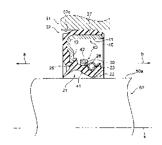
portion 105 a tension force against the rotary shaft. By this garter spring
107, improving tracking
of the rotary shaft by the seal lip 103 is attempted (for example, see patent
literature 1).
[Citation List]
[Patent Literature]
[0003]
[Patent Literature 1] JP 3278349
[Summary]
[Technical Problem]
[0004]
As described above, in the conventional sealing device 100, improving tracking
of the
rotary shaft by the seal lip 103 is attempted by the garter spring 107;
however, in a situation
1
CA 2975705 2017-08-08
where the sealing device 100 is used in a low-temperature environment, an
influence of the
garter spring 107 may weaken because the seal lip 103 becomes brittle, the
tension force arising
in the sealing lip 103 may decrease, and the tracking of the rotary shaft by
the seal lip 103 may
decrease. When the tracking of the rotary shaft by the seal lip 103 decreases,
a gap may arise
between the rotary shaft and the lip tip portion 105 such that an object of
sealing leaks from this
gap.
[0005]
In this manner, in the conventional sealing device 100, a configuration is
sought whereby
a decrease in the tracking of the rotary shaft by the seal lip 103 can be
suppressed even in a
situation of use in a low-temperature environment.
[0006]
The present invention is made in view of the problems described above and has
as an
object to provide a sealing device that can suppress a decrease in tracking a
rotary shaft.
[Solution to Problem]
[0007]
To achieve the object above, a sealing device according to the present
invention is
provided with a reinforcing ring that is annular around an axis; an elastic-
body portion that is
provided with a seal lip, is installed to the reinforcing ring, is formed from
an elastic body, and is
annular around the axis; an annular garter spring; and a lip-pressing ring
that is an annular
member; wherein the seal lip has on an inner-periphery side a lip tip portion
that is an annular
portion that is convex toward the axis, and on an outer-periphery side a
receiving groove that is
an annular groove formed facing away from the lip tip portion; the garter
spring is embedded in
the receiving groove of the seal lip; and the lip-pressing ring is configured
so the seal lip can be
inserted into a space on the inner-periphery side of the lip-pressing ring, a
value of an inner
diameter of the lip-pressing ring being no less than a value of an outer
diameter of an annular
portion that is at least a portion on the outer-periphery side of the seal
lip.
[0008]
In a sealing device according to one aspect of the present invention, the seal
lip is
connected to another portion of the elastic-body portion at an end portion on
one side in an axis
direction, the value of the inner diameter of the lip-pressing ring being no
less than a value of an
2
CA 2975705 2017-08-08
outer diameter of the seal lip at a portion at least partway toward the one
side from another side
in the axis direction.
[0009]
In a sealing device according to one aspect of the present invention, the lip-
pressing ring
is a member that is annular around an axis of the lip-pressing ring.
[0010]
In a sealing device according to one aspect of the present invention, the
inner diameter of
the lip-pressing ring is set so the inner-periphery side of the lip-pressing
ring contacts the outer-
periphery side of the seal lip before the seal lip is spread to the outer-
periphery side by a distance
corresponding to an interference of the seal lip.
[0011]
In a sealing device according to one aspect of the present invention, the
inner diameter of
the lip-pressing ring is set so the inner-periphery side of the lip-pressing
ring contacts the outer-
periphery side of the seal lip in a usage state.
[0012]
In a sealing device according to one aspect of the present invention, in a
cross section at
the axis, at least a portion of an outline on the inner-periphery side of the
lip-pressing ring
corresponds to at least a portion of an outline on the one side of the
receiving groove on the
outer-periphery side of the seal lip.
[Advantageous Effects of the Invention]
[0013]
According to the sealing device according to the present invention, a decrease
in tracking
a rotary shaft can be suppressed.
[Brief Description of Drawings]
[0014]
[FIG. 1] A cross-sectional view of a cross section at an axis for illustrating
a schematic
configuration of a sealing device according to an embodiment of the present
invention.
[FIG. 2] A partial enlarged cross-sectional view of a cross section at an axis
x of the
sealing device illustrated in FIG. 1.
3
CA 2975705 2017-08-08
[FIG. 3] A partial cross-sectional view for illustrating the sealing device
according to an
embodiment of the present invention in a usage state.
[FIG. 4] A cross-sectional view of a cross section at an axis for illustrating
a schematic
structure of one example of a conventional sealing device.
[Description of Embodiments]
[0015]
An embodiment of the present invention is described below with reference to
the
drawings.
[0016]
FIG. 1 is a cross-sectional view of a cross section at an axis x for
illustrating a schematic
configuration of a sealing device 1 according to an embodiment of the present
invention, and
FIG. 2 is a partial enlarged cross-sectional view of a cross section at the
axis x of the sealing
device 1 illustrated in FIG. 1. The sealing device 1 according to an
embodiment of the present
invention is used in an automobile, a general-purpose machine, or the like to
provide a seal
between a rotary shaft and a member having a through hole through which this
rotary shaft is
inserted, and is applied to, for example, provide a seal between a crankshaft
and a front cover in
an automobile engine. Hereinbelow, for convenience in description, the
direction of arrow a (see
FIG. 1) in an axis-x direction is defined as an outer side (one side) and the
direction of arrow b
(see FIG. 1) in the axis-x direction is defined as an inner side (other side).
More specifically, the
outer side is a side of an object of non-sealing and an atmosphere side that
ensures an absence of
an object of sealing, and the inner side is a side of the object of sealing
and a side that faces the
object of sealing, such as oil. Moreover, in a direction perpendicular to the
axis x (also "radial
direction" hereinbelow), a direction heading away from the axis x (the
direction of arrow c in
FIG. 1) is defined as an outer-periphery side and a direction approaching the
axis x (the direction
of arrow d in FIG. 1) is defined as an inner-periphery side.
[0017]
As illustrated in FIG. 1, the sealing device 1 is provided with a reinforcing
ring 10 that is
an annular member around the axis x, an elastic-body portion 20 formed from an
elastic body
that is annular around the axis x, an annular garter spring 30, and a lip-
pressing ring 40 that is an
annular member. The elastic-body portion 20 is installed integrally to the
reinforcing ring 10.
4
CA 2975705 2017-08-08
The reinforcing ring 10 is, for example, made of metal; metal material of the
reinforcing ring 10,
there is, for example, stainless steel and SPCC (cold-rolled steel). As the
elastic body of the
elastic-body portion 20, there is, for example, various types of rubber
materials. As the various
types of rubber materials, there is, for example, synthetic rubbers such as
nitrile rubber (NBR),
hydrogenated nitrile rubber (H-NBR), acrylic rubber (ACM), and fluororubber
(FKM).
[0018]
The reinforcing ring 10 is manufactured by, for example, pressing or forging,
and the
elastic-body portion 20 is molded by crosslinking molding (vulcanization)
using a molding die.
At a time of this crosslinking molding, the reinforcing ring 10 is disposed in
the molding die; the
elastic-body portion 20 is adhered to the reinforcing ring 10 by crosslinking
adhesion, and the
elastic-body portion 20 is molded integrally with the reinforcing ring 10.
[0019]
For example, as illustrated in FIG. 1, the reinforcing ring 10 is formed
annularly around
the axis x, a cross section at the axis x (also simply "cross section"
hereinbelow) exhibiting a
shape that is substantially L-shaped, and has a cylindrical portion 11 that is
a cylindrical portion
or a substantially cylindrical portion extending in the axis-x direction and a
flange portion 12 that
is a hollow, disk-shaped portion spreading from an outer-side end portion of
the cylindrical
portion 11 toward the inner-periphery side. Moreover, the cross section of the
reinforcing ring 10
has a constant or substantially-constant thickness.
[0020]
The elastic-body portion 20 is installed to the reinforcing ring 10 and, in
the present
embodiment, is formed integrally with the reinforcing ring 10 so as to cover
the reinforcing ring
10 from the outer side and the outer-periphery side. As illustrated in FIG. 1,
the elastic-body
portion 20 has a seal lip 21, and the seal lip 21 has on the inner-periphery
side an annular lip tip
portion 22 that is convex toward the axis x, and on the outer-periphery side
an annular receiving
groove 23 formed facing away from the lip tip portion 22. Specifically, as
illustrated in FIG. 1,
the elastic-body portion 20 has in addition to the seal lip 21 a dust lip 24
and a lip base portion
25. The lip base portion 25 is, in the elastic-body portion 20, an annular
portion positioned in a
vicinity of an inner-periphery-side end portion of the flange portion 12 of
the reinforcing ring 10;
the seal lip 21 is connected to the lip base portion 25 at an outer-side end
portion, is a portion
5
CA 2975705 2017-08-08
extending from the lip base portion 25 toward the inner side, and is disposed
opposing the
cylindrical portion 11 of the reinforcing ring 10. The dust lip 24 extends
from the lip base portion
25 to the outer side and toward the axis x.
[0021]
Specifically, the seal lip 21 has on an inner-side end portion the lip tip
portion 22, which
is wedge-shaped and annular and whose cross-sectional shape is convex toward
the inner-
periphery side. The lip tip portion 22 is formed so in a usage state, an inner-
periphery-side
pointed portion makes close contact with an outer peripheral surface of the
rotary shaft, which is
not illustrated. More specifically, an interference of the lip tip portion 22
against the rotary shaft
is set so the lip tip portion 22 contacts the outer peripheral surface of the
rotary shaft that is not
illustrated across a predetermined width in the axis-x direction. Note that
the lip tip portion 22
may be formed with a spiral protrusion or groove that enables formation of an
airflow toward a
side of the object of sealing (inner side) in an attempt to prevent leaking of
the object of sealing.
[0022]
Furthermore, as illustrated in FIG. 2, an outer-periphery-side outline of a
cross section of
the seal lip 21 extends from the receiving groove 23 toward the outer
side¨diagonally from an
inner-side rim of the receiving groove 23 to the inner-periphery side¨and,
upon reaching a
lowest point positioned farthest on the inner-periphery side, extends
diagonally to the outer-
periphery side and reaches the lip base portion 25. A shape of the outer-
periphery-side outline of
the cross section of the seal lip 21 is not limited to the shape described
above and may be another
shape; for example, the outline may be a curve, a straight line, or a
combination of a curve and a
straight line.
[0023]
Specifically, the dust lip 24 is a part that extends from the lip base portion
25, extending
from the lip base portion 25 in outer-side and inner-periphery-side
directions. By the dust lip 24,
attempted is prevention of intrusion of foreign matter such as mud water,
sand, or dust from the
outer side in a lip-tip-portion 22 direction in the usage state. The dust lip
24 may have a length in
this extending direction set so a tip portion thereof contacts the rotary
shaft that is not illustrated
in the usage state, and may have the length in the extending direction thereof
set so the tip
portion thereof does not contact the rotary shaft that is not illustrated in
the usage state.
6
CA 2975705 2017-08-08
[0024]
Furthermore, the elastic-body portion 20 has a rear cover 26 and a gasket
portion 27. The
rear cover 26 is a portion that covers from the outer side the flange portion
12 of the reinforcing
ring 10, and the gasket portion 27 is a portion that covers from the outer-
periphery side the
cylindrical portion 11 of the reinforcing ring 10. The gasket portion 27 is a
portion for fixing, in
the usage state, the sealing device 1 in the through hole of the member that
is not illustrated
through which the rotary shaft is inserted and, when the sealing device 1 is
pressed into the
through hole described above, is compressed in the radial direction between
this through hole
and the cylindrical portion 11 of the reinforcing ring 10 and generates a
mating force that is a
force in the radial direction. The gasket portion 27 has a thickness in the
radial direction set so a
mating force of a predetermined size arises when the sealing device is pressed
into the through
hole. As described above, the elastic-body portion 20 has portions that are
the seal lip 21, the
dust lip 24, the lip base portion 25, the rear cover 26, and the gasket
portion 27, and is formed
integrally from the elastic body.
[0025]
The garter spring 30 is an annular coil spring and is formed by, for example,
end portions
of the coil spring being joined together. The garter spring 30 is embedded in
the receiving groove
23 of the seal lip 21. In the usage state, the garter spring 30 presses the
lip tip portion 22 of the
seal lip 21 to the inner-periphery side in the radial direction and presses
the lip tip portion 22 to
the rotary shaft, imparting a tension force of a predetermined size to the lip
tip portion 22 against
the rotary shaft. When the rotary shaft is inserted into the sealing device 1
and the seal lip 21 is
spread to the outer-periphery side in correspondence with the interference,
the garter spring 30 is
spread to the outer-periphery side and stretched in a peripheral direction,
generating an elastic
force and pressing the lip tip portion 22 to the rotary shaft. In a free state
of the seal lip 21 where
the rotary shaft is not inserted into the sealing device 1, the garter spring
30 is at a natural length
and generates no elastic force. Moreover, the garter spring 30 may be
configured to be stretched
to generate an elastic force and bias the seal lip 21 to the inner-periphery
side in the free state of
the seal lip 21 as well.
[0026]
7
CA 2975705 2017-08-08
The lip-pressing ring 40 is a resin or metal annular member; it is configured
so the seal
lip 21 can be inserted into a space on the inner-periphery side of the lip-
pressing ring 40, and a
value of an inner diameter of the lip-pressing ring 40 is made to be a size
that is no less than a
value of an outer diameter of an annular portion that is at least a portion,
on the outer-periphery
side, of the seal lip 21. As described below, the lip-pressing ring 40 is
installed in the sealing
device 1 so that in the usage state the seal lip 21 is inserted therein and so
as to surround from the
outer-periphery side a portion of the seal lip 21 across the axis-x direction.
[0027]
Specifically, the lip-pressing ring 40 is a member that is annular around an
axis thereof
(axis x in FIGS. 1, 2) and is formed with a ring inner-peripheral surface 41
that is a surface on
the inner-periphery side, and a ring outer-peripheral surface 42 that is a
surface on the outer-
periphery side so outlines on the outer-periphery side and the inner-periphery
side draw a perfect
circle or a substantially-perfect circle in a cross section orthogonal to the
axis. Moreover, the
value of the inner diameter of the lip-pressing ring 40 is made to be a size
that is no less than a
value of an outer diameter of the seal lip 21 at a portion at least partway
toward the outer side
(one side) in the axis-x direction from the inner-side end portion.
[0028]
More specifically, as illustrated in FIG. 2, an inner diameter (pR that is a
minimum inner
diameter of the ring inner-peripheral surface 41 of the lip-pressing ring 40
is made to be a value
no less than an outer diameter (pL that is a maximum outer diameter in a
portion between an
inner-side end portion and a predetermined position on the outer side of the
receiving groove 23
on a seal lip outer-peripheral surface 28 that is an outer-periphery-side
surface of the seal lip 21.
By this, the seal lip 21 can be inserted inside the lip-pressing ring 40 from
an outer-side end
portion. Moreover, so the seal lip 21 can be inserted inside the lip-pressing
ring 40 from the
outer-side end portion, a diameter of the ring outer-peripheral surface 42 of
the lip-pressing ring
40 is set to be smaller than an inner diameter of a portion of the sealing
device 1 opposing the
seal lip 21 on the outer-periphery side. In the present embodiment, the
diameter of the ring outer-
peripheral surface 42 of the lip-pressing ring 40 is set to be smaller than an
inner diameter of the
cylindrical portion 11 of the reinforcing ring 10.
[0029]
8
CA 2975705 2017-08-08
Furthermore, more specifically, as illustrated in FIGS. 1, 2, with the lip-
pressing ring 40,
a shape of a cross section at the axis of the lip-pressing ring 40 is made to
be substantially
rectangular or substantially pentagonal; the ring inner-peripheral surface 41
has a wedge-shaped
cross-sectional shape, having a convex tapered surface on the inner-periphery
side, and the ring
outer-peripheral surface 42 is made to be a cylindrical surface or a
substantially-cylindrical
surface around the axis. In the present embodiment, for example, as
illustrated in FIG. 2, on the
seal lip outer-peripheral surface 28 of the seal lip 21, a portion on the
inner side of the receiving
groove 23 forms a protruding portion 29 that is an annular portion protruding
in an outer-
periphery direction; a diameter of the seal lip outer-peripheral portion 28 is
maximal at the
protruding portion 29. That is, diameters of portions other than the
protruding portion 29 in the
seal lip outer-peripheral surface 28 are less than the diameter of the
protruding portion 29, the
diameter of the protruding portion 29 having the outer diameter (pL ((pL <
yR). Because of this,
in a situation where the lip-pressing ring 40 is disposed coaxially with the
seal lip 21, an annular
space is formed between the ring inner-peripheral surface 41 of the lip-
pressing ring 40 and the
portions other than the protruding portion 29 in the seal lip outer-peripheral
surface 28 of the seal
lip 21.
[0030]
In a situation where the garter spring 30 is protruding to the outer-periphery
side of the
protruding portion 29 of the seal lip outer-peripheral surface 28 of the seal
lip 21 in a state where
the garter spring 30 is embedded in the receiving groove 23 of the seal lip
21, the seal lip 21 may
not be able to be inserted into the lip-pressing ring 40 past the receiving
groove 23. In this
situation, by inserting the seal lip 21 into the lip-pressing ring 40 in a
state where the garter
spring 30 is not installed in the receiving groove 23 of the seal lip 21 and
afterward installing the
garter spring 30 in the receiving groove 23 of the seal lip 21, the seal lip
21 can be inserted into
the lip-pressing ring 40 past the receiving groove 23.
[0031]
Furthermore, with the ring inner-peripheral surface 41 of the lip-pressing
ring 40, at least
a portion of the outline of the ring inner-peripheral surface 41 in the cross
section at the axis
thereof may correspond to at least a portion of an outline on an outer side of
the receiving groove
23 in the cross section of the seal lip outer-peripheral surface 28 of the
seal lip 21. By this, at
9
CA 2975705 2017-08-08
least a portion of the ring inner-peripheral surface 41 of the lip-pressing
ring 40 can be made to
make close contact with at least a portion of a portion on the outer side of
the receiving groove
23 in a surface of the seal lip outer-peripheral surface 28 of the seal lip 21
when the seal lip 21 is
spread to the outer-periphery side and contacts the ring inner-peripheral
surface 41 of the lip-
pressing ring 40.
[0032]
As described above, a specific example of the shape of the lip-pressing ring
40 is
illustrated, but the shape of the lip-pressing ring 40 is not limited to the
specific shape described
above. The shape of the lip-pressing ring 40 may be a shape that differs from
the specific
example described above; for example, the ring inner-peripheral surface 41 may
be a conical
surface, a cylindrical surface, a curved surface, or the like, and the ring
outer-peripheral surface
42 may be a conical surface, a curved surface, or the like. Moreover, while a
specific example of
the shape of the seal lip 21 is illustrated as described above, the shape of
the seal lip 21 is not
limited to the specific shape described above. The shape of the seal lip 21
may be a shape that
differs from the specific example described above; the outer diameter does not
have to be
maximal at the protruding portion 29, and the outer diameter may be maximal
at, for example, a
portion in a vicinity of the lip base portion 25 of the seal lip 21. However,
the inner diameter cpR
of the ring inner-peripheral surface 41 of the lip-pressing ring 40 is made to
be a value no less
than the outer diameter (pL that is the maximum outer diameter in the portion
between the inner-
side end portion and the predetermined position on the outer side of the
receiving groove 23 on
the seal lip outer-peripheral surface 28 of the seal lip 21. Moreover, with
the ring inner-
peripheral surface 41 of the lip-pressing ring 40, at least a portion of the
outline of the ring inner-
peripheral surface 41 in the cross section at the axis thereof preferably
corresponds to at least a
portion of the outline on the outer side of the receiving groove 23 in the
outline of the seal lip
outer-peripheral surface 28 in the cross section of the seal lip 21. Moreover,
the material of the
ring 40 may be any material.
[0033]
Furthermore, as described below, the diameter of the ring inner-peripheral
surface 41 of
the lip-pressing ring 40 is set so in the usage state of the sealing device 1
the seal lip outer-
peripheral surface 28 of the seal lip 21 spread out to the outer-periphery
side contacts the ring
CA 2975705 2017-08-08
inner-peripheral surface 41. Specifically, the inner diameter of the lip-
pressing ring 40 is set so
the ring inner-peripheral surface 41 of the lip-pressing ring 40 contacts the
seal lip outer-
peripheral surface 28 of the seal lip 21 before the seal lip 21 is spread to
the outer-periphery side
by a distance corresponding to the interference against the inserted rotary
shaft. For example, the
inner diameter of the lip-pressing ring 40 is set so the ring inner-peripheral
surface 41 of the lip-
pressing ring 40 contacts the seal lip outer-peripheral surface 28 of the seal
lip 21 when the seal
lip 21 is spread to the outer-periphery side by the distance corresponding to
the interference. In
this situation, by the lip-pressing ring 40, the seal lip 21 can be suppressed
from spreading to the
outer-periphery side without increasing a sliding resistance of the seal lip
21 in the usage state.
Moreover, for example, the inner diameter of the lip-pressing ring 40 may be
set so the ring
inner-peripheral surface 41 of the lip-pressing ring 40 contacts the seal lip
outer-peripheral
surface 28 of the seal lip 21 in the course of the seal lip 21 being spread to
the outer-periphery
side by the distance corresponding to the interference. In this situation, in
the usage state, the seal
lip 21 is imparted with a tightening force against the rotary shaft by the lip-
pressing ring 40 in
addition to the garter spring 30.
[0034]
Next, actions of the sealing device 1 having the configuration described above
are
described. FIG. 3 is a partial cross-sectional view for illustrating the
sealing device 1 according
to an embodiment of the present invention in the usage state. As illustrated
in FIG. 3, the sealing
device 1 is installed in a space between a rotary shaft 50 and a through hole
52 to provide a seal
in the usages state between the rotary shaft 50 and a housing 51 having the
through hole 52
through which this rotary shaft 50 is inserted. The rotary shaft 50 is, for
example, a crankshaft of
an automobile engine, and the housing 51 is, for example, a front cover.
[0035]
As illustrated in FIGS. 2, 3, in the sealing device 1 in the usage state, the
lip-pressing ring
40 has the seal lip 21 inserted therein and is disposed in a position past the
garter spring 30 or the
receiving groove 23 on the outer side in the axis-x direction (direction of
arrow a), the ring inner-
peripheral surface 41 opposing from the outer-periphery side the seal lip
outer-peripheral surface
28 of the seal lip 21.
[0036]
11
CA 2975705 2017-08-08
Furthermore, as illustrated in FIG. 3, in the usage state, the sealing device
1 is installed
pressed into the through hole 52 of the housing 51 and the gasket portion 27
of the elastic-body
portion 20 is compressed between the housing 51 and the reinforcing ring 10
and abuts an inner
peripheral surface 52a of the through hole 52 in a liquid-tight manner. By
this, a seal is provided
between the sealing device 1 and the through hole 52 of the housing 51.
Moreover, the lip tip
portion 22 of the seal lip 21 abuts an outer peripheral surface 50a of the
rotary shaft 50 in a
liquid-tight manner and so the rotary shaft 50 can slide, providing a seal
between the sealing
device 1 and the rotary shaft 50.
[0037]
In the usage state, the seal lip 21 through which the rotary shaft 50 is
inserted contacts the
outer peripheral surface 50a of the rotary shaft 50 at the lip tip portion 22,
is bent to the outer-
periphery side starting from a connection point thereof to the lip base
portion 25 or a portion in
this vicinity, and is spread to the outer-periphery side. The seal lip 21 is
spread to the outer-
periphery side by a distance corresponding to an interference of the lip tip
portion 22 against the
rotary shaft 50. The interference is set in advance corresponding to the shape
of the seal lip 21 or
the shape of the lip tip portion 22 and is set to a value where, for example,
the lip tip portion 22
contacts the rotary shaft 50 across a predetermined width in the axis-x
direction by the seal lip 21
being pushed to the outer-periphery side.
[0038]
As described above, in the usage state, the seal lip 21 has the rotary shaft
50 inserted
therethrough and is spread out to the outer-periphery side, at least a portion
of a portion on the
outer side of the garter spring 30 of the seal lip outer-peripheral surface 28
of the seal lip 21
contacting at least a portion of the ring inner-peripheral surface 41 of the
lip-pressing ring 40. As
described above, in a situation where the outline of the cross section of the
seal lip outer-
peripheral surface 28 of the seal lip 21 matches the outline of the cross
section of the ring inner-
peripheral surface 41 of the lip-pressing ring 40, in the usage state, the
ring inner-peripheral
surface 41 of the lip-pressing ring 40 makes close contact with the seal lip
outer-peripheral
surface 28 of the seal lip 21.
[0039]
12
CA 2975705 2017-08-08
By the ring inner-peripheral surface 41 of the lip-pressing ring 40 contacting
the seal lip
outer-peripheral surface 28 of the seal lip 21 in the usage state, the seal
lip 21 is suppressed from
spreading to the outer-periphery side by a distance greater than the distance
corresponding to the
interference. In a situation where the rotary shaft 50 is misaligned from the
axis x, the seal lip 21
is pushed toward the outer-periphery side in a direction of misalignment, but
a portion of the seal
lip 21 in the direction of misalignment is pushed strongly and spreads to the
outer-periphery side,
and a gap arising between a portion of the seal lip 21 on an opposite side in
the radial direction
from this portion in the direction of misalignment and the rotary shaft 50 is
suppressed. This is
because the lip-pressing ring 40 is in contact with the seal lip outer-
peripheral surface 28 of the
seal lip 21. Even if the seal lip 21 is pushed to the outer-periphery side in
one portion, the lip-
pressing ring 40 is pushed to the outer-periphery side at a portion contacting
this one portion of
the seal lip 21 such that an entirety of the lip-pressing ring 40 is pushed to
the outer-periphery
side, and a portion opposing in the radial direction this one portion of the
seal lip 21 is pressed in
a direction of being pressed to the rotary shaft 50 by the lip-pressing ring
40. In this manner, the
lip-pressing ring 40 can improve a performance of the seal lip 21 of tracking
the rotary shaft 50.
[0040]
The lip-pressing ring 40 has the inner diameter (pR thereof set relative to
the outer
diameter TL of the seal lip 21 so as to contact the seal lip outer-peripheral
surface 28 of the seal
lip 21 before the lip tip portion 22 is spread to the outer-periphery side by
the distance
corresponding to the interference. In a situation where the lip-pressing ring
40 has the inner
diameter TR thereof set relative to the outer diameter TL of the seal lip 21
so as to contact the
seal lip outer-peripheral surface 28 of the seal lip 21 when the lip tip
portion 22 is spread to the
outer-periphery side by the distance corresponding to the interference¨that
is, in a situation
where the inner diameter TR thereof is set relative to the outer diameter TL
of the seal lip 21 so
the lip-pressing ring 40 contacts the seal lip outer-peripheral surface 28 of
the seal lip 21 when
the rotary shaft 50 is inserted into the sealing device 1¨in the usage state,
when the rotary shaft
50 is not misaligned but is rotating normally, the lip-pressing ring 40
generates no tightening
force in the seal lip 21 against the rotary shaft 50. Because of this, in a
situation where the lip-
pressing ring 40 has the inner diameter TR thereof set relative to the outer
diameter TL of the
seal lip 21 so as to contact the seal lip outer-peripheral surface 28 of the
seal lip 21 when the lip
13
CA 2975705 2017-08-08
tip portion 22 is spread to the outer-periphery side by the distance
corresponding to the
interference, an increase in a sliding resistance against the rotary shaft 50
can be avoided.
[0041]
Meanwhile, in a situation where the lip-pressing ring 40 has the inner
diameter (pR
thereof set relative to the outer diameter (pL of the seal lip 21 so as to
contact the seal lip outer-
peripheral surface 28 of the seal lip 21 in the course of the lip tip portion
22 spreading to the
outer-periphery side by the distance corresponding to the interference, in the
usage state, the lip-
pressing ring 40 generates a tightening force in the seal lip 21 against the
rotary shaft 50 by
pressing the seal lip 21 to the inner-periphery side. Because of this, the lip-
pressing ring 40 can
increase the performance of the seal lip 21 of tracking the rotary shaft 50.
[0042]
Furthermore, as illustrated in FIG. 3, in a situation where in the cross
section the outline
of the ring inner-peripheral surface 41 of the lip-pressing ring 40
corresponds to the outline of
the seal lip outer-peripheral surface 28 of the seal lip 21, in the usage
state, the lip-pressing ring
40 is housed, making close contact with the seal lip outer-peripheral surface
28 of the seal lip 21.
Because of this, the lip-pressing ring 40 moving in the axis-x direction can
be suppressed and a
stability of an installation position of the lip-pressing ring 40 in the usage
state can be improved.
[0043]
Furthermore, because the lip-pressing ring 40 is of a separate material than
the seal lip 21,
it does not inhibit a desired movement of the seal lip 21.
[0044]
As described above, according to the sealing device 1 according to the present
embodiment, in the usage state, the lip-pressing ring 40 contacts the seal lip
21 from the outer-
periphery side; therefore, the spread of a portion of the seal lip 21 to the
outer-periphery side due
to misalignment of the rotary shaft 50 and a gap forming between the rotary
shaft 50 and the seal
lip 21 on the opposite side can be suppressed. Because of this, a sealing
performance of the seal
lip 21 can be improved. Particularly, even in a situation where the seal lip
21 becomes brittle in a
usage state at a low temperature and the tension force of the seal lip 21
against the rotary shaft 50
imparted to the seal lip 21 by the garter spring 30 decreases, the tracking of
the rotary shaft 50 by
the seal lip 21 can be maintained by the lip-pressing ring 40.
14
CA 2975705 2017-08-08
[0045]
In this manner, according to the sealing device 1 according to the present
embodiment, a
decrease in tracking the rotary shaft 50 can be suppressed.
[0046]
An embodiment of the present invention is described above, but the present
invention is
not limited to the sealing device 1 according to the embodiment of the present
invention above
and includes all aspects included within the concept of the present invention
and the scope of
claims. Moreover, configurations may be selected and combined as appropriate
so at least a
portion of the object and effects described above is exhibited. For example,
shapes, materials,
dispositions, sizes, and the like of the components in the embodiment above
can be changed as
appropriate according to specific usage aspects of the present invention.
[0047]
Specifically, forms of the reinforcing ring 10 and the elastic-body portion 20
may be
other forms. Moreover, the elastic-body portion 20 may be one provided with no
dust lip 24.
[0048]
Furthermore, while the sealing device 1 according to the present embodiment is
applied
to an automobile engine, the application object of the sealing device
according to the present
invention is not limited thereto; the present invention is applicable to all
configurations that can
utilize the effects exhibited by the present invention, such as a rotary shaft
of another vehicle, a
general-purpose machine, or an industrial machine.
[Reference Signs List]
[0049]
1, 100 Sealing device
10, 101 Reinforcing ring
11 Cylindrical portion
12 Flange portion
20, 102 Elastic-body portion
21, 103 Seal lip
22, 105 Lip tip portion
23, 106 Receiving groove
CA 2975705 2017-08-08
24, 104 Dust lip
25 Lip base portion
26 Rear cover
27 Gasket portion
28 Seal lip outer-peripheral surface
29 Protruding portion
30, 107 Garter spring
40 Lip-pressing ring
41 Ring inner-peripheral surface
42 Ring outer-peripheral surface
50 Rotary shaft
51 Housing
52 Through hole
x Axis
(pL Outer diameter
(pR Inner diameter
16
CA 2975705 2017-08-08