Note: Descriptions are shown in the official language in which they were submitted.
=
= CA 02975776 2017-08-03
WO 2016/124164 PCT/DE2015/100498
MIXING DEVICE WITH INTEGRATED DELIVERY PUMP
The invention at hand relates to a mixing device with an
integrated delivery pump, and in particular to a mixing
device for intermixing powder particles and/or granular
particles or a similar free-flowing solid with at least one
liquid, the mixing device comprising a feed duct for the
solid, an inlet for the liquid, at least one mixing
implement, which is rotatable about an axis in a mixing
chamber, and an outlet for the mixture.
Such a mixing device is known from DE 19629945 Al and
serves the purpose of incorporating solids, such as powder,
granulates and bulk goods into a liquid template. Solid and
liquid are fed separately. During operation, a highly
turbulent zone is created by rotating the mixing implement.
A low pressure is created thereby, by means of which the
solid and the liquid are sucked into the mixing chamber.
In the case of liquids with high viscosity, there is the
danger that the suction effect is not sufficient in order
to establish the desired liquid throughput.
In the case of high viscosity, the liquid throughput and
thus the suction effect for the solid decrease in the feed
duct. As the viscosity of the liquid increases, the device
loses the ability to absorb solids. The same applies for
mixtures, the viscosity of which increases during the
course of the mixing process. This problem can be reduced
by connecting an external pump, e.g. a displacement pump,
which intensifies the suction effect and maintains the
liquid throughput. This solution, however, is extensive
with respect to construction.
There is thus the object of creating a device of the above-
mentioned type, which can be constructed in a simple and
compact manner and which is suitable to also process
84028614
- 2 -
liquids with a high viscosity or mixtures with a variable
viscosity.
According to an aspect of the present invention, there is
provided a mixing device for intermixing powder particles and/or
granular particles or a similar free-flowing solid with at least
one liquid to form a mixture, the mixing device comprising: a
feed duct for the solid; an inlet for the liquid; at least one
mixing implement, which is rotatable about an axis in a mixing
chamber; and an outlet for the mixture; a delivery pump, which
is arranged between the inlet and the mixing implement located
in the mixing chamber in a delivery stage of the mixing device;
wherein the feed duct for the solid leads into the mixing
chamber, and wherein the mixing implement is formed by a rotor-
stator device with a rotor rim and a stator rim.
Advantageous embodiments are specified in the following
description.
According to the invention, a mixing device is created for
intermixing powder particles and/or granular particles or a
similar free-flowing solid with at least one liquid, the mixing
device comprising a feed duct for the solid, an inlet for the
liquid, at least one mixing implement, which is rotatable about
an axis in a mixing chamber, an outlet for the mixture, and a
delivery pump, which is arranged between the inlet and the
mixing implement.
The invention at hand is based on the knowledge that an even,
stable liquid throughput can be attained by means of the
integrated delivery pump, even if liquids with high or
increasing viscosity are processed. This is in particular
advantageous, when the device has a return, i.e. when the
Date Recue/Date Received 2022-06-10
84028614
- 2a -
mixture is guided back into the liquid container and is fed to a
new processing again.
The liquid throughput in particular also remains stable, when
the feed of the solid is released, e.g. by opening a valve,
which is provided for this purpose, in the feed duct for the
solid. In contrast, a "breakdown" of the suction effect and thus
of the feed of the liquid and/or of the solid can occur at least
temporarily in the case of common mixing devices.
The invention provides for the delivery pump to be arranged
between the inlet and the mixing implement, thus to be arranged
upstream of the mixing implement with respect to the delivery
direction of the solid, and downstream from the inlet. The
suction effect is thus improved, without
Date Recue/Date Received 2022-06-10
CA 02975776 2017-08-03
- 3 -
'impeding the feeding of solid into the mixing chamber or
having to avoid this by means of constructive measures.
In one embodiment, the outlet and/or the inlet is arranged
horizontally or laterally and/or the feed duct is arranged
vertically and in particular centrally. The outlet is
arranged above the inlet. The pump is thereby arranged
downstream from the inlet and upstream of the outlet in
feeding direction of the liquid. The geometric center of
the cross section of the feed duct is aligned with the axis
of rotation of the mixing implement.
In one embodiment of the invention, the feed duct is
arranged vertically and eccentrically with respect to the
axis of rotation of the mixing implement. The fed solid
comes into contact with the mixing implement outside of the
center of the mixing implement. The mixing process thus
takes place in a zone with a higher circumferential speed
and on/at the mixing implement. The mixture is subjected to
higher turbulences in this area of the mixing implement.
In one embodiment of the invention, the feed duct can be
closed by means of a seal or a plug or a pressure piston,
wherein the seal or the plug or the pressure piston can be
moved in the feed duct along the feed direction of the
solid and is flush with the walls of the feed duct. An
intermixing of a certain amount of liquid with a certain
amount of solid is possible without adding unwanted mass
flows, in particular air or solid or liquid. This
embodiment has the advantage that the walls of the feed
duct remain clean and do not need to be cleaned
additionally. Deposits are avoided. The seal can also be
embodied for a simple sealing.
In one embodiment of the invention, a further connection
exists between the delivery pump and the mixing chamber,
wherein the further connection is formed by a pipe or a
= CA 02975776 2017-08-03
- 4 -
'line on the outside of a housing of the mixing device, and
, has an opening into the mixing chamber. The further
connection forms a bypass line for the liquid between the
delivery stage and the mixing chamber. A portion of the
delivered liquid reaches into the mixing chamber via an
opening. The solid is thus brought into contact with the
liquid from a plurality of sides. The liquid is thus
distributed more evenly in the mixing chamber. Local
overconcentrations or underconcentrations of solid are
reduced.
In one embodiment of the invention, the further connection
is arranged inside the housing of the mixing device, the
further connection is in particular a connecting channel,
which is embodied in the housing. Further lines, which run
along the outside, can be forgone. Leakiness at the
exterior lines and the risk of damages can be avoided. This
embodiment further has the advantage that the design of the
mixing device can be kept to be highly compact.
In one embodiment of the invention, the opening of the
further connection is formed by an annular gap and/or at
least one bore and/or at least one nozzle. Depending on the
arrangement or intended use of the mixing device, different
types of the opening can be provided. Different mixtures,
which require different types of wetting, can thus be
processed. In the particularly advantageous embodiment of
the opening as annular gap, the liquid can be introduced
into the mixing chamber in the form of a liquid curtain.
This improves the wetting of the fed solid in a transition
area between the solid and the liquid. Local
overconcentrations of solid are avoided by means of the
improved wetting. The formation of residues by the bonding
and/or adhering of insufficiently wetted solids is
prevented. The formation of clumps is avoided. A local
overheating of fed solid is also prevented by means of the
additional feeding of liquid. This can occur when the
insufficient liquid feed creates local overconcentrations
CA 02975776 2017-08-03
- 5 -
'of solid, which can be subjected to high temperatures due
to friction with the mixing implement. The mixing chamber
can furthermore be rinsed with cleaning fluid in a simple
and efficient manner. It is thus no longer necessary to
open the mixing device in order to clean it (so-called
"cleaning-in-place" characteristic).
In one embodiment of the invention, the annular gap is
arranged above the mixing chamber with respect to the
delivery direction of the liquid, in particular around the
feed duct. The arrangement of the annular gap "on the
ceiling" of the mixing chamber has the advantage that the
fed liquid can run into the mixing chamber with the aid of
gravity and forms a liquid curtain. The wetted surface of
the liquid is increased, whereby the solid is wetted more
quickly. This contributes to the improved dispersion. The
arrangement of the annular gap around the feed duct ensures
an even liquid distribution. The fed solid is wetted
evenly. This prevents clumping as a result of local liquid
deficiency.
In one embodiment, the delivery pump is formed by a
centrifugal pump comprising a delivery wheel comprising a
plurality of conveying vanes, in particular four or eight
preferably curved conveying vanes. Such a delivery pump can
be realized in a structurally simple manner, so that
existing constructions can be upgraded with relatively
little effort.
In an alternative embodiment, the delivery pump is formed
by a rotor-stator device comprising one or a plurality of
rotor and/or stator rims in concentric arrangement.
Possible agglomerates in the mixture are comminuted by
means of this embodiment and an additional fine dispersion
of the mixture is attained. This is in particular the case
when the mixture recirculates, i.e. is fed to the mixing
process again.
CA 02975776 2017-08-03
- 6
In one embodiment, the conveying vanes or rotor and/or
stator rims are arranged on the side of the delivery pump
facing away from the mixing implement. Such an arrangement
has a particularly good suction effect.
In one embodiment, the delivery pump is arranged on the
same drive shaft as the mixing implement. Only a single
drive motor is thus required for the mixing implement and
the delivery pump.
In one embodiment, the outlet empties into an outline line,
which leads back into a container for the liquid, which is
connected to the liquid feed via a feed line. It is thus
possible for the starting material from the container to
gradually intermix more and more with the solid and to be
delivered back again and again, until a desired total
mixture is created, which has a corresponding degree of
homogeneity and/or viscosity.
In an advantageous embodiment, the mixing device is
embodied in a modular manner, with a mixing module
comprising the mixing implement, a delivery module
comprising the delivery pump, and an inlet module
comprising the inlet, wherein the delivery module can be
arranged between the mixing module and the inlet module,
and the inlet module can be arranged directly on the mixing
module. According to this embodiment, it is possible to
provide individual modules and to combine them with one
another or to omit them. The delivery pump can for example
not be required for the processing of a liquid with a low
viscosity. It is possible in this case to remove the
delivery module and to directly connect the mixing module
to the inlet module. If a liquid with a high viscosity is
to be processed by means of the mixing device, the delivery
module can be added (subsequently).
CA 02975776 2017-08-03
- 7 -
'Exemplary embodiments of the invention will be described in
more detail below by means of the drawings. In partly
schematized illustration:
Figure 1 shows a mixing device according to an embodiment
of the invention in cross section;
Figure 2 shows the mixing device from Figure 1 without
delivery module;
Figure 3 shows a perspective view of the delivery wheel of
the mixing device from Figure 1;
Figure 4 shows a top view onto the delivery wheel from
Figure 3;
Figure 5 shows a mixing device according to a further
embodiment of the invention in cross section;
Figure 6 shows a mixing device according to a further
embodiment of the invention comprising a bypass
line in cross section;
Figure 7 shows a mixing device according to an embodiment
of the invention comprising an eccentric feed
duct in cross section;
Figure 8 shows a mixing device according to a further
embodiment of the invention comprising an
internal bypass line in cross section; and
Figure 9 shows a mixing device according to a further
embodiment of the invention in cross section.
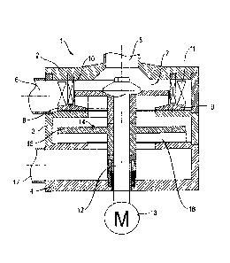
Figure 1 shows a mixing device 1 according to one
embodiment of the invention. The mixing device is of
modular construction and comprises a mixing module 2, a
CA 02975776 2017-08-03
- 8 -
'delivery module 3 and an inlet module 4. The modules 2, 3
and 4 are connected to one another, but can be detached
from one another and can be connected to one another in a
different way. Figure 2 shows an alternative, in the case
of which provision is not made for a delivery module 3 and
the mixing module 2 is directly connected to the inlet
module 4.
The mixing module 2 has a vertical central feed duct 5 for
feeding a solid as well as a horizontal lateral outlet 6
for the mixture. The feed duct 5 and the outlet 6 empty
into a mixing chamber 7, in which a mixing implement 8 is
arranged, which is formed by a rotor-stator device 9, 10
comprising a rotor rim 11 and a stator rim. The rotor 9 is
connected to a rotating drive shaft 12, which is driven by
means of a motor 13.
In the delivery module 3, which is connected to the mixing
module 2, provision is made for a delivery pump 14, which
is embodied as centrifugal pump, comprising a delivery
wheel 15 and a plurality of conveying vanes 16, which are
arranged on the delivery wheel 15. The conveying vanes 16
are arranged on the side of the delivery wheel 15, which
faces away from the mixing module 2. The delivery wheel 15
as well as the rotor is connected to the drive shaft 12 and
is rotated by rotation of the drive shaft 12.
The inlet module 4 is connected on the end of the delivery
module 3, which is shown on the bottom in image
orientation. The inlet module 4 comprises a horizontal
lateral inlet 17 for the liquid.
The inlet 17 is connected to a liquid container, which is
not shown. The outlet 6 can also be connected to the liquid
container, so that a closed circuit is formed and the
mixture can be delivered back into the liquid container and
can be fed to the mixing process again.
CA 02975776 2017-08-03
- 9
During operation, i.e. in response to the rotation of the
rotor 9 and of the delivery wheel 15, the solid is sucked
into the mixing chamber 7 through the feed duct 5. Due to
the particle acceleration by means of the rotor 9, an
underpressure is in particular created in the mixing
chamber 7, which has the effect that powders or granules
are sucked through the feed duct 5. The rotor 9 is embodied
and arranged in such a way that the solid is initially
delivered separately from the liquid and encounters the
liquid only in a predetermined area with a high turbulence.
The solid is thereby accelerated within the rotor 9 and is
finely distributed prior to the dispersion into the liquid
due to the volume increase towards the edge area of the
rotor 9. The finely distributed solid particles then
encounter a liquid jacket comprising a relatively large
surface, so that they are dispersed into the liquid in an
agglomerate-free manner.
The delivery pump 14 creates an additional suction effect,
so that it is ensured that sufficient liquid and solid
reach into the mixing chamber 7, even if the liquid has a
high viscosity or if the viscosity thereof increases during
the mixing process.
Figure 3 and 4 show the delivery wheel 15 according to the
embodiment of the invention illustrated in Figure 1. The
delivery wheel 15 has eight conveying vanes 16, each of
which have a curvature and extend from the radially outer
edge of the delivery wheel in the direction of a hub 18,
wherein the radially inner end of the conveying vanes 16 is
spaced apart from the hub 18.
Figure 5 shows a mixing device 1 according to a further
embodiment of the invention at hand. The embodiment in
Figure 5 differs from the embodiment in Figure 1 in that
the delivery pump 14 is formed by a rotor/stator device
CA 02975776 2017-08-03
- 10 -
'comprising a rotor 19 and a stator 20. The rotor 19
comprises at least one rotor rim 21. A particularly fine
dispersion is attained by means of this embodiment. This is
in particular the case, when the mixture recirculates, i.e.
is fed to the mixing process again.
Figure 6 shows an embodiment of the invention comprising a
further connection 22 between the delivery module 3 and the
mixing chamber 7. The further connection runs outside of a
housing 23 on the outside thereof, from a horizontally
external side of the delivery module 3 to an outside of the
mixing module 2. The further connection 22 forms a bypass
line for the liquid delivered by the delivery pump 14. The
terms further connection and bypass line will be used
synonymously hereinafter. A portion of the delivered liquid
can bypass the delivery duct along the axis of the delivery
pump 14 between the delivery module 3 and the mixing module
2 via the further connection 22 and can reach directly back
into the mixing module 2. The further connection 22 is
formed by a hose or pipe line. The further connection 22
has an opening 24, which leads into the mixing chamber 7.
The opening 24 is located on the side located opposite the
mixing implement 8 - in the illustrated orientation on the
upper side - of the mixing chamber 7, so that the liquid
can run into the mixing chamber 7 with the aid of gravity.
The opening 24 is formed by means of an annular gap 25. The
annular gap 25 surrounds the feed duct 5 concentrically. In
this embodiment, the feed duct 5 is aligned with the axis
of the mixing implement 8.
Figure 7 shows an embodiment of the invention comprising an
eccentric feed duct 5 and an exterior bypass line 22. The
feed duct 5 is arranged so as to be displaced with respect
to the axis of the mixing implement 8. The opening 24 of
the bypass line 22, which is embodied as annular gap 25, is
expanded inside the housing 23 of the mixing device 1 in
such a way that the annular gap 25 also runs concentrically
around the feed duct 5.
CA 02975776 2017-08-03
- 11 -
Figure 8 shows an embodiment of the invention, wherein the
further connection 22, which forms the bypass line, inside
the housing 23 of the mixing device 1 runs along the
delivery direction of the liquid - ascending in the
illustrated orientation - from the delivery module 3 to the
mixing module 2. The opening 24 is also located completely
in the interior of the housing 23 of the mixing device 1.
The bypass line 22 is completely integrated into the
housing 23 of the mixing device 1 and forms a channel,
which is completely surrounded by the housing 23.
Figure 9 shows an embodiment comprising an eccentric feed
duct 5. The feed duct 5 is closed by means of a piston 26.
The piston 26 is arranged so as to be capable of being
displaced along the feed direction of the solid in the feed
duct 5. The piston 26 is flush with the walls of the feed
duct 5 and forms a closed hollow space with the housing 23
and the mixing chamber 7. By means of a corresponding
integration of the piston 26, the seal of the mixing
chamber 7 is embodied in a pressure-resistant manner. Solid
to be fed is guided into the mixing chamber 7 by moving the
piston 26 along the feed duct 5.
CA 02975776 2017-08-03
- 12 -
'List of Reference Numerals
1 mixing device
2 mixing module
3 delivery module
4 inlet module
feed duct
6 outlet
7 mixing chamber
8 mixing implement
9 rotor
stator
11 rotor rim
12 drive shaft
13 motor
14 delivery pump
delivery wheel
16 conveying vane
17 inlet
18 hub
19 rotor
stator
21 rotor rim
22 further connection (bypass line)
23 housing of the mixing device
24 opening
annular gap
26 piston