Note: Descriptions are shown in the official language in which they were submitted.
DISH ROTATION DIRECTLY DRIVEN FROM TRANSPORT BELT
BACKGROUND OF THE INVENTION
[0002] The present invention relates to a system to transport and
identify an item under
test such as a container used to evaluate a biological sample for the presence
or absence of
microorganisms (e.g. bacteria, fungi). Such containers are typically referred
to as petri dishes or
simply dishes. Such containers are also referred to as culture plates or
simply plates.
[0003] Automated medical testing systems utilize a track to move the
containers ("dish"
hereinafter) for processing from one location to another, The dishes are
inspected and identified
at various locations as they are processed for testing and/or tracking. For
example, the BD
Kiestra system offers multiple stations or modules or workbenches at which
sample cultures in
the dish undergo procedures and/or testing. Each dish must be identified
before and/or after each
such procedure or test to maintain accurate diagnostic records of the dish.
Regular inspection of
the dish ensures process integrity and ties all of the tests performed on the
specific sample used
to inoculate the culture media in the dish.
[0004] Previous methods of identifying a dish along the track utilize a
bat-code scanner
and a scanning platform. The dish is stopped by mechanical means at a point
along the track. A
pneumatic cylinder raises the dish above a moving track and rotates the dish.
A vacuum is
provided to maintain the position of the dish on the cylinder. A barcode
affixed to a side of the
dish is scanned by the barcode scanner. The pneumatic cylinder then lowers the
dish back onto
the track to move the dish to another location.
[0005] The system for reading the bat-code requires a multitude of
moving parts to raise
and rotate the dish. One motor is used to drive the transport belt and another
motor to rotate the
cylinder. The approach also increases the time needed to transport the dish
from location to
location because of the need to raise, scan, and lower the dish at each
location where the dish is
inspected.
CA 2975942 2018-10-16
CA 02975942 2017-08-04
WO 2016/124665 PCT/EP2016/052336
[0006] Therefore, a need exists for an improved system of reading barcodes
as dishes are
transported from station to station in a multi-station processing system.
BRIEF SUMMARY OF THE INVENTION
[0007] One aspect of the disclosure describes an apparatus for reading a
barcode
comprising a dish having a barcode, a transport belt, a bumper stopper having
a first position at a
first distance from the transport belt and a second position at a second
distance from the transport
belt, a rotator, and a barcode scanner. In some embodiments, the transport
belt moves the dish in
a first direction toward the bumper stopper, and the bumper stopper contacts
the dish when the
bumper stopper is in the second position. The bumper stopper can deflect the
dish in a second
direction toward the rotator, and the rotator can align the dish with the
barcode scanner.
[0008] The apparatus may comprise an actuator to move the bumper stopper
between the
first position and the second position. In some embodiments, the actuator may
be a pneumatic
cylinder. The apparatus may further comprise at least one guide rail adjacent
the transport belt.
[0009] The rotator can comprise a disc and a shaft extending from the disc.
The rotator
may further comprise a contact surface extending circumferentially around the
disc. The
apparatus may further comprise a motor to drive the transport belt and may
also include a drive
train to couple the motor to a pulley wheel adapted to drive the transport
belt. In some
embodiments, the dish moves toward the rotator when the bumper stopper is in
the second
position.
[0010] One aspect of the disclosure describes an apparatus for reading a
machine
readable label affixed to a dish. The apparatus has a transport belt adapted
to carry the dish with
one machine readable label from location to location. The apparatus is
equipped with a bumper
stopper, a rotator having a shaft, a first pulley wheel coupled to the shaft,
and a scanner. The
transport belt is configured to both carry the dish and rotate the first
pulley wheel to position the
dish label for reading. The scanner reads the machine readable label when the
dish is properly
oriented for the label to be read.
[0011] In some embodiments, the bumper stopper moves between a first
position and a
second position with a component of motion transverse to the motion of the
transport belt. The
dish can move along a path and the bumper stopper may be at least partially
within that path
when the bumper stopper is in the second position. The bumper stopper can
guide the dish into
2
CA 02975942 2017-08-04
WO 2016/124665 PCT/EP2016/052336
contact with the rotator. The apparatus may also include a plurality of second
pulley wheels to
align the transport belt. In some embodiments, the transport belt
simultaneously carries the dish
and rotates the first pulley wheel. The transport belt may comprise two
generally parallel tracks.
The tracks provide a stable and balanced surface used to carry the dishes. The
belt configuration
is largely a matter of design choice. The skilled person is aware of many
different suitable belt
configurations. Guard rails may be positioned adjacent the transport belt
along the length of the
transport belt.
[0012] Another aspect of the disclosure describes an apparatus comprising a
means for
moving a container, a means for temporarily stopping the container, a means
for rotating the
container, and a means for reading a barcode affixed to the container. The
means for
transporting the container may comprise a transport belt. The means for
temporarily stopping
the container and the means for rotating the container may oppose one another
across the means
for moving the container.
BRIEF DESCRIPTION OF THE DRAWINGS
[0013] A more complete appreciation of the subject matter of the present
invention and
the various advantages thereof can be realized by reference to the following
detailed description,
in which reference is made to the accompanying drawings:
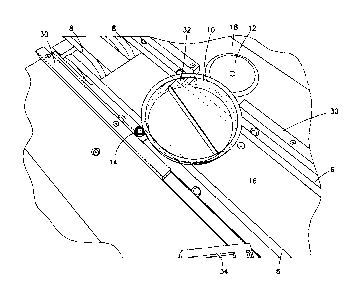
[0014] Fig. 1 is a perspective view of a transport belt, bumper stopper,
rotator, and dish
in accordance with one embodiment of the current invention.
[0015] Fig. 2 is a rear perspective of the transport belt, bumper stopper,
rotator, and dish
of Fig. 1.
[0016] Fig. 3 is a bottom perspective view of pulley wheels, shaft, gear,
timing belt,
motor, motor shaft, and bearing in accordance with one embodiment of the
current invention.
[0017] Fig. 4 is a perspective view of the cabinet floor, bearing, motor,
motor shaft, gear,
and timing belt in accordance with one embodiment of the current invention.
DETAILED DESCRIPTION
[0018] A barcode scanning apparatus according to one embodiment of the
invention
includes a transport belt 6 as shown in Figs. 1-3. Transport belt 6 is shown
as two generally
parallel, spaced apart flexible belts which extend along an upper deck 16 of
the conveyor.
However, the transport belt could also be a single flexible or rigid conveyor
belt or any number
3
CA 02975942 2017-08-04
WO 2016/124665 PCT/EP2016/052336
of different known belt designs and configurations. The present invention is
not limited to a
specific belt design or configuration. The "two belt" configuration described
herein provides
stable transport for the dishes described herein. The transport belt 6 is
coupled to one or more
pulley wheels 8. As explained in more detail below, the pulley wheels 8 may be
driving
members to rotate the transport belt 6. The transport belt is preferably a
continuous member that
forms a loop. Additional pulley wheels (not shown) may be positioned at a
remote location
along the upper deck at the end of the transport belt 6. The transport belt 6
extends around the
pulley wheel 8 and through the upper deck 16.
[0019] The apparatus is adapted to convey a dish 10 which has a machine
readable
identifier 32 affixed to it. In the embodiment shown in Figs. 1-2, the
identifier is a one
dimensional barcode. However, other machine readable identifiers are also
possible (e.g. two
dimensional barcode, RFID, EAS tag). The dish 10 shown is a conventional petri
dish with a
standard diameter (3.5 inches). However, the present invention can be adapted
to convey any
one of a number of different sample containers. When the transport belt is
comprised of more
than one individual belt, the distance between the belts is less than the
diameter of the dish so
that both belts support the dish.
[0020] A bumper stopper 14 is adjacent the transport belt 6. In the
embodiment shown,
the bumper stopper 14 is a pneumatic cylinder which extends through the upper
deck 16. A
bearing can be attached to the pneumatic cylinder to allow rotational motion
about the cylinder
axis. The pneumatic cylinder moves the bumper stopper 14 between a first
position and a second
position. In the first position, the proximal end of the bumper stopper 14
does not extend further
from the upper deck 16 than the transport belt 6. In the second position, the
bumper stopper 14
extends further above the upper deck 16 than the transport belt 6. The bumper
stopper could also
be configured to move from any direction in relation to the transport belt
(e.g. from above, from
the side).
[0021] A rotator 12 is adjacent the transport belt 6, preferably opposite
the bumper
stopper 14. In the embodiment shown, the rotator 12 is a disc with a shaft 20
extending from it
(the shaft is best seen in Fig. 3). The rotator may have a contact surface 18
extending
circumferentially about the disc. The contact surface may be a different
material than the disc
(e.g. rubber, plastic) to provide a high friction contact surface with the
disc. The shaft 20 extends
CA 02975942 2017-08-04
WO 2016/124665 PCT/EP2016/052336
through the upper deck 16 and is coupled to a pulley wheel 22 such that
rotation of the pulley
wheel causes rotation of the shaft 20.
[0022] A scanner 34 is positioned in the vicinity of the transport belt 6
and rotator 12
(best seen in Figs. 1-2). The scanner can be any scanner adapted to read
machine readable
identifiers (e.g. barcode scanner, RFID sensor, EAS detector). In the
embodiment shown, a
Microscan MS-3 Scanneris used . The scanner 34 can be positioned a distance
from the
transport belt 6 provided that the scanner is able to read the identifier from
the distance at which
it is placed.
[0023] One or more guide rails 30 extend along the path of the transport
belt 6. As
shown in Figs. 1-2, the guide rail 30 is interrupted by the rotator 12. The
guide rail 30 extends
above the transport belt 6 to maintain the position of the dish 10 on the
belt.
[0024] The transport belt 6 loops around the pulley wheel 8 and extends
below the upper
deck 16. As shown in Fig. 3, the transport belt 6 interweaves through pulley
wheels 22. The
pulley wheels 22 are secured to the bottom of the upper deck 16 by a fastener
(e.g. screw, nut
and bolt, rivet) which permit the pulley wheels to rotate about the fastener.
The pulley wheels
maintain the alignment of the transport belt 6 throughout the system. Shaft 20
is coupled to a
bearing 26 which is attached to a surface 28 (best seen in Fig. 4) to secure
the shaft 20 in place.
[0025] In some embodiments, the transport belt can be tensioned to maintain
its position
on the pulley wheels by first calculating the length of the path which the
transport belt will
travel. The length can then be multiplied by a reduction percentage (e.g. 6 to
10 percent, or more
preferably, 8 percent). The transport belt can then be trimmed to that length
and interweaved
through the system described herein. The ends of the trimmed transport belt
can then be attached
to each other by welding, adhesive, or similar methods known to one of skill
in the art.
[0026] The transport belt is moved by a motor such as a Maxon Amax 11W
motor with
an 84:1 gearbox. However, any suitable motor and gearbox are contemplated. The
skilled
person can select a motor suitable for use in the present invention. As shown
in Figs. 3-4, the
motor 36 is positioned below the upper deck 16. The motor 36 may be coupled to
the shaft (not
shown) of the pulley wheel 8 by a drive train configured to transfer motion to
the transport belt
6. For example, the motor shaft 38 is coupled to a gear 40. A similar gear
could also be
positioned on the pulley wheel shaft and a timing belt 42 transfers rotational
motion between the
CA 02975942 2017-08-04
WO 2016/124665 PCT/EP2016/052336
shafts. Alternatively, the motor shaft could be in alignment with, and
directly coupled to, the
pulley wheel shaft, thereby eliminating the need for a gear and timing belt
arrangement.
[0027] As the motor 36 transfers motion to the pulley wheel 8 via the drive
train, the
pulley wheel causes the transport belt 6 to move. The motion of the transport
belt 6 moves the
dish 10 toward the bumper stopper 14. The dish 10 contacts the bumper stopper
14 when it is in
the second (raised) position. The transport belt continues to move and the
stopper 14 does not
fully impair movement of the dish 10 but instead guides the dish 10 toward the
rotator 12.
[0028] The dish 10 contacts the first surface 18 of the rotator 12 as a
result of the
guidance from the bumper stopper 14. The rotator 12 is continuously rotating
while the transport
belt 6 is in motion because the transport belt 6 rotates the pulley wheel 22
and shaft 20. The
rotator 12 rotates the dish 10 to align the machine readable identifier 32
with the scanner 34.
The bearing on the bumper stopper 14 may rotate about its axis as the dish 10
rotates.
[0029] The rotator 12 can be configured to rotate at the same speed as the
transport belt.
The rotator speed can be faster or slower than the speed of the transport
belt. Hence the rotator
speed is largely a matter of design choice. The rotator speed is influenced at
least in part by the
scanner sensitivity. A faster scanner can allow for faster rotation of the
dish. The dish is rotated
at least one complete rotation by the rotator to ensure that the machine
readable label on the dish
is read regardless of where it is placed on the dish relative to the label's
initial placement relative
to the scanner. In one embodiment, the rotation takes about one to two
seconds.
[0030] Once the identifier 32 has been read by the scanner 34, the
pneumatic cylinder
can move the bumper stopper 14 into the first position, allowing the dish 10
to be conveyed away
by the transport belt 6. The scanner can be connected to a computer or
electronic controller (e.g.
microprocessor, PLC controller) that moves the bumper stopper once the barcode
is read. If the
scanner fails to read the barcode the bumper stopper can be configured to
allow the dish to pass
after a few seconds and mark the dish as "unknown". The guide rail 30
maintains the position of
the dish 10 on the transport belt 6 as the dish continues to move with the
belt.
[0031] The movement of the transport belt 6 is uninterrupted even when the
dish 10 is
temporarily held in place by the bumper stopper 14 and rotator 12. The
continuous movement of
the transport belt allows any other dishes on the belt to continue to be
advanced in the apparatus
6
CA 02975942 2017-08-04
WO 2016/124665 PCT/EP2016/052336
while the machine readable identifier on a dish is being read, thereby
confirming the identity of
the dish under test.
[0032] In the embodiment shown in Figs. 1-4, the rotator is driven by the
transport belt.
However, the rotator can also be driven independently of the transport belt so
it can spin in both
directions. This could be achieved by coupling a second motor to the rotator
wheel.
[0033] Although the invention herein has been described with reference to
particular
embodiments, it is to be understood that these embodiments are merely
illustrative of the
principles and applications of the present invention. It is therefore to be
understood that
numerous modifications may be made to the illustrative embodiments and that
other
arrangements may be devised without departing from the spirit and scope of the
present
invention as defined by the appended claims.
7