Note: Descriptions are shown in the official language in which they were submitted.
CA 02976118 2017-08-09
WO 2015/123732 PCT/AU2015/050067
1
METHOD FOR FABRICATING A COMPOSITE CONSTRUCTION
ELEMENT
TECHNICAL FIELD
The present invention relates to fabricating construction elements, being
objects used to construct a building, bridge or similar structure. In
particular, the invention relates to fabricating a composite construction
element having at least two portions having different material properties.
BACKGROUND TO THE INVENTION
When constructing a building, a common approach to create internal and
external walls, as well as floors and roofs, is to install pre-fabricated
panels
known as Structurally Insulated Panels (SIPs). SIPs are a composite
construction element consisting of a foamed material core sandwiched
between two substantially rigid, structural planar sheets or boards. These
panels are popular as they can allow the efficiency of a building project to
be improved, as the large, structural and generally lightweight panels can
be installed quickly and easily, they are strong and have high insulation
values.
An SIP typically comprises a polymer foam core, such as polystyrene foam
or polyurethane foam, joined to two planar sheets formed from a range of
materials including plywood, metal or cement.
Whilst SIPs may offer some advantages over other construction techniques,
they also suffer from some drawbacks. For example, as SIPs are configured
as planar panels, this inherently limits the geometry of structures which can
be formed from SIPs.
Conventional SIPs also suffer from the drawback of having foam cores
formed from organic foamed materials, which have proven to be highly
flammable and present a significant fire risk.
Furthermore, due to the construction of a conventional SIP, a panel will only
support less than a specified maximum load in limited orientations.
CA 02976118 2017-08-09
WO 2015/123732 PCT/AU2015/050067
2
Accordingly, it would be advantageous to provide a construction element
having similar properties as an SIP which has a non-planar or complex
geometry, and/or which can support a load exerted thereon from various
orientations, or that may be structurally optimised to support particular
loads according to functional requirements.
Furthermore, it would be useful to provide a solution that avoids or
alleviates any of the disadvantages present in the prior art, or which
provides an alternative to prior art approaches.
SUMMARY OF THE INVENTION
According to one aspect of the invention there is provided a method for
fabricating a composite construction element using a computer-controlled
apparatus, the method involving the steps of receiving, by the apparatus,
computer instructions relating to a core geometry, moving and selectively
operating the apparatus to selectively fabricate a core comprised of a first
building material, corresponding with the core geometry, selectively
applying a settable second building material to at least a portion of the
core,
thereby forming a skin of settable second building material, and at least
partially curing the skin to form a shell at least partially enclosing the
core.
According to a further aspect of the invention, the apparatus further
comprises a milling spindle and/or a material deposition head in
communication with a supply of the first building material, and the selective
fabrication of the core involves selectively milling a block of the first
building
material to remove portions of first building material, or selectively
depositing portions of the first building material, in either case,
progressively fabricating the core.
According to another aspect of the invention, the selective application of the
settable second material involves one or more of dipping the at least a
portion of the core in a bath of the settable second material and selectively
spraying the at least a portion of the core with the settable second material,
to form the skin.
CA 02976118 2017-08-09
WO 2015/123732 PCT/AU2015/050067
3
BRIEF DESCRIPTION OF THE DRAWINGS
Preferred embodiments of the invention will now be described, by way of
example only, with reference to the accompanying drawings in which:
Figures 1A and 1B show a core of a composite construction element being
fabricated with a computer-controlled milling spindle;
Figures 2A and 2B show a core of an alternative composite construction
element being fabricated with a computer-controlled material deposition
apparatus;
Figure 3A shows a further alternative composite construction element
partway through fabrication;
Figure 3B shows the composite construction element shown in Figure 3A
being fabricated with a computer-controlled milling spindle;
Figures 4A and 4B show two assemblies prior and post integration with a
composite construction element;
Figures 5 and 6 show two different rectilinear composite construction
elements;
Figures 7A to 7E show stages of fabricating a further alternative composite
construction element having integrated services;
Figures 8A to 8C are partial section views of two alternative multi-layer
composite construction elements;
Figure 9 is a cross-section of an alternative complex construction element
having integrated architectural fittings;
Figures 10A to 1OF illustrate a preferred, actual and adjusted geometry of
an alternative composite construction element; and
Figures 11A to 11C are cross-section views of three alternative edge strip
components.
CA 02976118 2017-08-09
WO 2015/123732 PCT/AU2015/050067
4
DETAILED DESCRIPTION OF PREFERRED EMBODIMENTS
The following disclosure relates to methods for fabricating composite
construction elements. Construction elements are generally any object used
to construct part of a building, bridge or similar structure, including
smaller
structures such as landscape elements, or may form the entire structure. A
composite construction element comprises at least two portions having
different properties, typically formed from different materials. In
particular,
the disclosed methods employ computer-controlled apparatus to fabricate a
composite construction element responsive to computer instructions derived
from a computer model of the composite construction element. In order to
fabricate the composite construction element, the apparatus is guided by
the computer instructions to fabricate a core from a first building material,
by selectively removing and/or applying a first building material, and
covering at least a portion of the core with a settable second building
material to form a skin. The settable second material is then cured to form
a shell. Further processes may be performed to affect the structure and/or
appearance of the composite construction element.
Reference will be made throughout this specification to 'computer
instructions' which at least partly relate to computer instructions derived by
a computer application from a three-dimensional (3D) model of the
construction element. The 3D model may be created by a user operating
modelling software, such as computer aided design (CAD) software, or by a
computer algorithm, or by a combination of these two approaches. The
instructions specify, amongst other things, the movement of the computer-
controlled apparatus and the operation of one or more attachments
connected to the apparatus and adapted to fabricate a construction
element, such as the milling head.
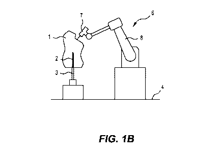
Figures 1A-1B show the initial stages of fabricating a composite construction
element, where a construction element core 9 is fabricated.
In Figure 1A, a block 1 of first building material is shown affixed to a
locator
pin 2 connected to a docking station 3 secured to the ground 4. For
CA 02976118 2017-08-09
WO 2015/123732 PCT/AU2015/050067
illustrative purposes, the block 1 has a notional profile 5 demarcated
thereon, indicating a desired construction element core geometry. The
locator pin 2 is generally removably connected to the block 1 and removed
after fabrication of the core 9. However in some instances the locator pin 2
may be left in place to assist with moving the finished construction element,
for example, when installing the element to a structure or removing the
element from a structure for maintenance. The core 9 may also have a
plurality of locator pins 2 (not shown) or female connectors (not shown),
potentially arranged at intervals around a peripheral region, to assist with
these purposes.
In Figure 1B, the assembly shown in Figure 1A is located adjacent to a
computer-controlled apparatus 6. The apparatus 6 has a milling head 7
attached to a movable robotic arm 8. Responsive to computer instructions
relating to the desired construction element core geometry, the arm 8
moves the milling head 7 relative to the block of material 1 and selectively
operates the milling head 7, thereby removing specific portions of the block
1 to fabricate the core 9, which corresponds with the desired construction
element core geometry.
Figures 2A-2B show the initial stages of fabricating an alternative composite
construction element, where an alternative construction element core 17 is
fabricated.
In Figure 2A an alternative block of material 10 is shown affixed to the floor
4 via the locator pin 2 and docking station 3. At least some of the external
surfaces of the block 10 have additional portions of first building material
11
arranged thereon.
In Figure 2B, the block 10 is located adjacent to an alternative computer-
controlled apparatus 12. The apparatus has a material deposition head 14
attached to a movable robotic arm 13. The deposition head is in fluid
communication with a supply of substantially liquid first building material,
which may be stored in a reservoir 15, via one or more hoses 16.
Responsive to computer instructions relating to a desired construction
CA 02976118 2017-08-09
WO 2015/123732 PCT/AU2015/050067
6
element core geometry, the arm 13 moves the material deposition head 14
relative to the block of material 1 and selectively operates the material
deposition head 14, successively depositing portions of the first material 11
in specific locations to fabricate the core 17, which corresponds with the
desired construction element core geometry. The portions of first building
materials 11 are typically deposited as beads of material, which typically
form layers. Each layer may be formed of a single continuous bead, or a
plurality of beads. Each layer may also be planar, or non-planar and three-
dimensional, for example, having double-curved or faceted portions. It will
be appreciated that deposition includes extrusion, jetting or spraying of the
first building material.
It will be appreciated that whilst the computer-controlled apparatus 12 is
shown in Figure 2B depositing portions of first building material 11 directly
on to the surfaces of the block 10, the apparatus 12 may also deposit first
material directly onto the ground 4 or any other substrate to fabricate the
core 17. The presence of the block 10 is optional depending on a number of
factors such as the availability of depositable first material, the geometry
of
the core 17, or time available to deposit the first material.
Optionally, the computer-controlled apparatus 12 is adapted to have inter-
changeable fabrication heads, allowing the material deposition head 14 to
be replaced with a milling head (not shown), such as previously discussed in
relation to Figure 1B. In this scenario, the apparatus 12 may perform a
further stage of fabrication and remove specific portions of the deposited
first material with the milling head, in order to refine the surface finish of
the core 17, such as adding fine decorative or functional features. The steps
of selective deposition and selective milling may also be repeated a number
of times in order to fabricate specific features in the core 17.
The core 9, 17 preferably defines a plurality of voids, in order to reduce the
mass of material required to fabricate the core 9, 17 and the weight of the
core 9, 17. This may be achieved by using a foamed material, which
comprises a pre-determined quantity of gas bubbles, as the first building
material. Such materials are preferably fire retardant, readily available,
light
CA 02976118 2017-08-09
WO 2015/123732 PCT/AU2015/050067
7
weight and provide good sound and/or temperature insulation. An inorganic
foamed material is typically suitable for these purposes, such as basalt, or
in some instances a combination of inorganic and organic foamed materials
would be suitable, thereby allowing a fireproof outer shell of basalt to be
formed. Also, for at least the outer surfaces of the core 9, 17, it is
preferable to use an open cell foamed material, as this provides a greater
mechanical connection with a second building material skin. This is
discussed further below.
Optionally, the core 9, 17 is fabricated from a non-regular density first
building material, thereby allowing specific portions of the core 9, 17 to be
fabricated having different densities. This may be achieved by varying the
density of gas bubbles in a foamed first building material during fabrication
of the core 9, 17. For example, the block 1 may comprise a laminated block
(not shown) having different layers formed from different density foams,
and the apparatus 6 fabricate the core 9 from the laminated block, as
detailed above in relation to Figures 1A-1B. Alternatively, the core 17 may
be fabricated by varying the gas content of a foamed first building material
during deposition of various layers or beads of first building material by the
apparatus 12, as detailed above in relation to Figures 2A-2B.
Alternatively, the density of the first building material is varied and non -
uniform by selectively adding additional materials to the first building
material. For example, this may also involve the material deposition head
14 being in communication with a supply of fibres, or wood flour, which is
selectively mixed with the first building material to adjust its density,
prior
to being deposited and forming part of the core 17. This would allow layers
of strata to be formed through the core 17. The ratio of first building
material to additional material may be varied significantly. For example,
where the first building material is a foam and the additional material is
glass fibres, the foam may be present in such a low quantity to simply hold
the fibres together, thereby allowing a heavier layer or portion to be
fabricated.
CA 02976118 2017-08-09
WO 2015/123732 PCT/AU2015/050067
8
In Figure 3A, a composite construction element 20 is shown elevated above
a bath 22 of substantially liquid, settable second building material. The
construction element comprises a core 21 at least partly covered with the
settable material, forming a skin 23 thereon. The core 21 has complex
cfreeform') geometry fabricated by either of the processes described above.
The skin 23 has been applied by dipping the core 21 into the bath 23,
whereby the settable building material covers and adheres to each
submerged portion of the core 21.
The dipping process is performed by a computer-controlled apparatus (not
shown) adapted to lift the core 21 by one or more locator pins (not shown)
connected to the core 21 and dip the core 21 into the bath of settable
building material 22, guided by computer instructions. This may be the
apparatus 6, 12 that fabricated the core 21, or a different apparatus.
Following being dipped one or more times, the core 21 is drained and the
skin 23 cured to form a shell 24 that at least partially encloses the core 21.
Optionally, the steps of dipping and curing may also be repeated to form a
second shell (not shown) located on a previously uncoated portion of the
core, or at least partially enclosing the first shell.
Alternatively, the composite construction element 20 is fabricated by
spraying the core 21 with the settable second building material to form the
skin 23 (not illustrated). The spraying is typically performed by the
apparatus 6, 12 that fabricated the core 21, where the apparatus 6, 12 has
a spray-gun attachment (not shown) attached to the robotic arm 8, 13 and
in communication with a supply of the settable second building material.
Responsive to computer instructions relating to a desired skin 23 geometry,
the arm 8 moves the material deposition head 14 relative to the core 21
and selectively sprays the settable building material onto the core 21,
successively depositing portions of the settable building material in specific
locations to fabricate the skin 23. Once the skin 23 is formed, it is at least
partially cured prior to a second skin being applied, or fully cured to form
the shell 24. The second skin may comprise a different settable material,
CA 02976118 2017-08-09
WO 2015/123732 PCT/AU2015/050067
9
thereby forming a plurality of shell layers having different material
properties.
The settable second building material is preferably a fine, cementitious
composition that flows rapidly around the core 21, filling or coating recesses
therein and adhering to the surfaces of the core 21, particularly where an
open cell foam has been used as the first building material, and cures
rapidly to form a strong, rigid shell 23. This may involve additional curing
processes to accelerate the curing of the shell 23, such as exposing the
shell 23 to a heated gas and/or liquid, or spraying a chemical setting agent
or catalyst onto the shell 23. Optionally, prior to dipping the core 21 in the
bath 22, or spraying the core 21 with the settable second material, the core
21 may be selectively sprayed by the apparatus 6, 12 with one or more
materials to assist the settable material adhering to the core 21, such as
fine fibrous filaments or an adhesive. Further optionally, this may include
applying a chemical setting agent or catalyst to the core 21 to accelerate
curing of the shell 24. Settable second building material compositions may
include one or more of cement, concrete, gypsum, ceramic or geopolymer.
Figure 3B shows an optional further stage of fabrication in which the
construction element 20 is reconnected to the docking station 3 and the
milling head 7 of the computer-controlled apparatus 6 removes specific
portions of shell from the construction element 20. This may be to refine
the external surfaces of the element 20 to fit within tolerances and/or to
add decorative or functional features to the shell. For example, specific
portions of the element 20 may be milled to ensure the element 20 is able
to be assembled onto a larger structure or for other components, such as
window or door frames, to be connected to the element 20. Alternatively,
signage text or braille details may be milled into specific portions of the
element 20.
Figure 4A shows an assembly 30 comprising a reinforcement bar Crebar')
frame 31 having a plurality of threaded connectors 32, the frame 31 spaced
apart from a base 33 also having threaded connectors 34. The frame 31 has
mesh panels 35 attached between at least some of the frame members. The
CA 02976118 2017-08-09
WO 2015/123732 PCT/AU2015/050067
assembly 30 replaces the block 10 in the fabrication process described in
relation to Figures 2A and 2B, typically being arranged in place, adjacent
the apparatus 12, by a gripper attachment (not shown) connected to the
apparatus 12, prior to deposition of first building material by the material
deposition head 14. The assembly 30 can prove useful in a number of
situations as the rebar frame 31 provides structural integrity for a core (not
shown) fabricated on or around the frame 31, and the mesh panels 35
provide a surface for first building material to be deposited on and adhered
to. The threaded connectors 32, 34 also assist fixing and moving the
assembly 30 during the fabrication process, and fixing the finished
composite construction element (not shown) to other like elements or a
structure to which the element is connected to.
Figure 4B shows an alternative assembly 41 within a multi-layer composite
construction element 40. The composite element 40 is shown in partial
section for illustrative purposes. The assembly 41 comprises a rebar frame
arranged as a cage 42 and a plurality of threaded connectors 43. The
composite construction element 41 has been formed by fabricating an inner
core 44 from a low density foam, according to the fabrication process
described in relation to Figures 1A-1B or Figures 2A-2B. The assembly 41
has been arranged around the inner core 44 and dense fibre foam layer 45
fabricated by the material deposition head 14 selectively depositing the
fibre filled foam on the inner core 44 and the cage 42. An outer core 46 has
then been fabricated by the material deposition head 14 depositing a
medium density foam on the fibre foam layer 45. An outer shell 47 has then
been fabricated by dipping the assembly 41 and layers 44-46 in a reservoir
of the settable second material, or spraying the settable second material on
the outer core 46. The settable material is then cured to form a rigid shell
47.
In Figure 5, a cross-section of a composite construction element 50 is
shown, the element 50 configured as a substantially rectilinear wall or
ceiling panel. The element 50 is fabricated according to the process steps
described above, and has a core 51 formed from a first, lightweight material
CA 02976118 2017-08-09
WO 2015/123732 PCT/AU2015/050067
11
and a shell 52 arranged around the core 51 formed from a second, rigid
material. The core 51 includes a services conduit 53, functional surface
finishes 54 and decorative surface finishes 55. The services conduit 53 is
adapted to receive conventional service components (not shown), such as
power and data cables. The functional finishes 54 may include an acoustic
treatment, signage text, braille or other functional textures to improve the
shell's resistance to loading or abrasion. The decorative features 55 may
include two or three dimensional textures and recesses. The panel 50 also
includes a stepped joint 56 to assist placement and fixing of the panel 50 to
adjacent panels or other structures. The joint 56 also helps reduce dust and
moisture ingress into a structure which the panel 50 is attached to.
Figure 6 shows an alternative composite construction element 60,
configured as a substantially rectilinear wall or ceiling panel. Construction
element 60 comprises many identical features to element 50, whereby
corresponding reference numerals indicate corresponding features. The
element 60 also includes a post-tension conduit 61 for receiving tensioning
means (not shown) to secure the element 60 to an adjacent panel or
structure. Tensioning means may include recessed dowels, tensioning
cables or fibres, high strength flexible glues and the like. The decorative
features 55 of the element are adapted to provide the appearance of period
architectural features, such as a particular cornice moulding.
Figures 7A-7E illustrate cross-sectional views of the various stages of
fabricating a construction element having integrated services.
Figure 7A shows a core 70, formed from a first building material and
fabricated using one or more of the process steps detailed above. The core
70 is configured as a substantially rectilinear panel having planar front 71
and rear 72 surfaces. The rear surface 72 has a plurality of services
conduits 73 arranged therein. A separate in-fill panel 74, adapted to seal
one of the services conduits, is shown spaced apart from the rear surface
72. The core 70 also has a plurality of rib recesses 75, extending from the
rear surface 72 towards the front surface 71. Each rib recess 75 has two
opposing walls spaced apart a predetermined distance. The core 70 also has
CA 02976118 2017-08-09
WO 2015/123732 PCT/AU2015/050067
12
two stepped joints 76 extending at each side, adapted to connect to an
adjacent panel or structure.
Figure 7B shows the core 70 with various services 77-79 inserted into the
services conduits 73 and the in-fill panel 74 inserted into a complimentary
conduit 73. The services include a waste water pipe 77, cooled water pipes
78 (to create a 'chilled beam' feature) and hot and cold water pipes 79. It
will be appreciated that these are merely examples of the different services
which may be installed into the core and that many other services may also
be inserted into the services conduits 73.
Figure 7C shows the core 70 having integrated services 77-79 during a
dipping stage, the core 70 partially submerged in a bath 80 of substantially
liquid, settable second building material.
Figure 7D shows the core 70 after being completely submerged in the bath
80 and lifted above the bath 80 to drain excess second building material. A
layer of second building material 81 has adhered to the core 70 and filled
each exposed rib recess 75 and services conduit 73.
Figure 7E shows a finished composite construction element 82, after the
layer of second building material has hardened to form a solid, monocoque
shell 84 that encloses the core 70. The hardened shell 84 seals each of the
services it is in contact with, providing a high level of fire protection and
insulation to the sealed services. The shell 84 also extends within each of
the rib recesses 73, where, once solidified, the shell 84 forms structural
ribs
83, increasing the strength and stiffness of the element 82.
Optionally, it is preferable that the width of each rib recess 75 is less than
double the width of the shell, to ensure that the hardened shell material
entirely fills each rib recess 75. Alternatively, the width of each rib recess
75 is more than double the width of the shell, to ensure that an air gap
between each side of each rib recess 75 is maintained.
Figure 8A shows an alternative multi-layer composite construction element
90 in partial section view for illustrative purposes. The construction element
CA 02976118 2017-08-09
WO 2015/123732 PCT/AU2015/050067
13
90 comprises an inner core 91, formed from a low density foam, and an
outer core 92, formed from a fibre reinforced material, such as a fibre-filled
foam, fibre-filled cement or glass reinforced concrete (GRC). The core 91
includes a plurality of tapered rib recesses 93 which the outer core 92 fills.
The outer core is at least partially encased in a shell 94 to provide a smooth
outer surface. The construction element 91 is fabricated using the
fabrication processes described above. In particular, the outer core 92 is
fabricated by the apparatus 12 either selectively depositing or spraying the
fibre reinforced material onto the core 91, ensuring that the rib recesses 93
are filled with the fibre reinforced material, thereby providing structural
enhancement to the construction element 90.
Figure 8B shows a further alternative multi-layer composite construction
element 95, in partial section view, having many identical features to
construction element 90, where corresponding reference numeral indicating
corresponding features. Construction element 95 includes a plurality of
reinforcement bars 96 inserted into each rib recess 93 and held apart by
spacing plates 97. The outer core 92 fills each rib recess 93 thereby joining
the reinforcement bars 96 to the core 91.
Figure 8C is a detailed perspective view of the reinforcement bars 96 and
one of the spacing plates 97.
In Figure 9, a cross-section view of an alternative composite construction
element 100 is shown having 'freeform', complex geometry and
architectural fittings attached thereto, being a glazing channel 101 and
window 102. The element 100 includes a core 103, formed from a first,
lightweight building material, fabricated according to one of the techniques
detailed above. The core 103 includes surfaces that are curved in all three
dimensions, including undercut features, and a network of conduits 104
extending therethrough. The core 103 has been dipped in a settable second
building material, to form an external skin of the settable building material.
The skin has then cured to form a rigid shell 105 that encloses the core 103
and fills each conduit 104, thereby forming a respective network of
structural braces.
CA 02976118 2017-08-09
WO 2015/123732 PCT/AU2015/050067
14
The geometry of the conduits 104 has been arranged to ensure that the
structural braces are located appropriately to support a load the element
100 will be subjected to. The arrangement of the conduits 104 may be
performed manually, for example, when a user is creating the 3D model of
the construction element 100, or may be due to a computer application
executing an algorithm, responsive to a data relating to loads the element
100 will be subjected to, to calculate an optimised conduit layout. The
conduits 104 may also be arranged to assist the settable second building
material to flow through each conduit 104 during a dipping process,
minimising the time required to fill each conduit 104 with material and/or
expel air from each conduit 104.
The dimensions of the structural conduits 104 may be determined
responsive to the shell 105 thickness. For example, the width of each
conduit 104 may be specified to not exceed double the thickness of the shell
105, to ensure that each conduit 104 is entirely filled by the solidified
shell
105.
Optionally, the shell 105 may be processed post-curing by the apparatus 6,
by selectively removing portions of the shell 105. This may be to refine the
shell 105 surfaces to allow the architectural fittings 101, 102 to be
accurately connected to the construction element 100.
Figures 10A-10F illustrate various scenarios relating to corner and/or edge
finishes, when fabricating a further alternative composite construction
element 110.
Figure 10A shows a core 111 of the construction element 110, produced by
one or more of the fabrication processes described above.
In Figures 10B-10C, a cross-section and detailed cross-section view of the
desired construction element 110 geometry are shown, the element 110
comprising the core 111 and a shell 112. The element 110 is a configured
as a rectilinear panel, having substantially planar surfaces and sharp
CA 02976118 2017-08-09
WO 2015/123732 PCT/AU2015/050067
corners and edges. The shell 112 is fabricated according to a dipping or
spraying process, as described above.
In Figures 10D-10E, a cross-section and detailed cross-section view of the
construction element 110 are shown, illustrating the actual geometry of the
shell 112 after application to the core 111. Due to the surface tension of the
second building material that forms the shell 112 being unable to support
the creation of sharply defined corners and edges, the corners and edges of
the shell 112 are rounded.
In Figure 10F, a detailed cross-section view of the construction element 110
is shown, the element comprising an alternative core 113. To attempt to
address the rounding of the edges of the shell 112, the alternative core 113
has an optimised edge geometry, comprising two ramped portions 114 that
are inclined away from the surface each ramp 114 is joined to, and join
each other at a point. The ramped portions 114 are arranged to retaining
settable building material in place, along each desired sharp edge, during
curing, to allow the shell 112 to form sharp corners and edges.
Figures 11A-11C are cross section views of various edge strips 120-122 for
connecting to an edge of a core, prior to the settable material being applied
and cured. Similar to the geometry of the core 113 described above, the
edge strips 120-122 help control the surface tension rounding of edges, and
assist a shell to form a sharp edge.
Figure 11A shows a right-angled edge strip 120 connected to a core 123
and surrounded by a shell 126. The right-angled edge strip 120 comprises
two core engaging arms 124 secured to respective surfaces of the core 123
either side of an edge, and a barrier arm 125 joined to the engaging arms
124 and extending away from the edge, typically at 45 to each surface the
engaging arms 124 are secured to.
Figure 11B shows a custom angle edge strip 121 connected to an
alternative, non-regular shaped core 127 and surrounded by a shell 128.
The custom angle edge strip 121 comprises two core engaging arms 129
CA 02976118 2017-08-09
WO 2015/123732 PCT/AU2015/050067
16
secured to respective surfaces of the core 127 either side of an edge, and a
barrier arm 130 joined to the engaging arms 129 and extending away from
the edge. As custom angle edge strip 121 may need to follow three-
dimensional curves along the edge, it is typically 3D printed, to allow for
efficient customisation.
Figure 11C shows an insert edge strip 122 connected in a recess in a further
alternative core 131 and surrounded by a shell 132. The insert edge strip
123 comprises two recess engaging arms 133 secured to inside surfaces of
the recess, and a barrier structure 134 connected to the engaging arms 133
and extending away from the recess.
It will be apparent that obvious variations or modifications may be made to
the present invention which are in accordance with the spirit of the
invention and intended to be part of the invention. Although the invention is
described above with reference to specific embodiments, it will be
appreciated that it is not limited to those embodiments and may be
embodied in other forms.