Note: Descriptions are shown in the official language in which they were submitted.
CA 02976742 2017-08-15
WO 2017/096493 PCT/CA2016/051513
VEHICLE POSITIONING WITH RFID TAGS
Cross-Reference to Related Application
[001] The present application claims priority on U.S. provisional patent
application no.
62/270,112 having a filing date of December 21, 2015, the contents of which
are hereby
incorporated by reference in their entirety.
Technical Field
[002] This patent application relates to the field of vehicle positioning
and particularly of
vehicle positioning using RFID tags. This patent application also relates to
the field of
embedding RFID tags and particularly embedding RFID tags in vehicle wheels and
more
particularly to embedding RFID tags in vehicle tires. This application also
relates to providing
RFD capability to vehicles and more particularly to providing RFID reading
capability in
proximity to a vehicle wheel.
Background
[003] GPS systems are available on vehicles to provide vehicle positional
information to
users as well as to onboard systems using vehicle positional information and
even in some cases
to external systems such as to fleet tracking systems.
[004] GPS solutions are less than perfectly accurate because of errors in
acquiring their
pseudo-ranges. With the Government no longer degrading the signal the majority
of the error
come from several factors which include
a. Atmosphere: As the signal passes through the ionosphere (a band of ions and
free
electrons, between 80 and 120 mile up) its speed is reduced. This delays the
signals arrival at the receiver, thereby effecting the distance calculation.
The
amount of water vapor in the atmosphere can also affect this time delay.
b. Timing: The clocks in the satellites are very near perfect (million dollar
atomic
clocks) but the clocks in the receivers are not as good. A discrepancy of
1/100th
of a second can make for an 1800-mile change in position, maybe putting you in
a
different Country or even continent.
1
CA 02976742 2017-08-15
WO 2017/096493 PCT/CA2016/051513
c. Multipathing: The signal from a satellite can be reflected off of a
building or some
other large reflective object before reaching the receiver, again delaying its
arrival. If the direct signal is also acquired, the software in most modern
receivers
can reject the indirect signals. But multipath can confuse the calculations
for
position.
d. Satellite Positional Errors: The gravitational pull of the sun and moon on
a
satellite can distort its orbit. These minor disturbances can add some error.
e. Satellite Geometry: The relative position of the satellites to each
other in the sky
above you can affect the accuracy. The intersection of four or more pseudo-
ranges
gives you a position but as the angle between the satellites gets smaller (or
as the
satellites get closer to each other) the effect of the above errors on the
resulting
position is increased. If all of the satellites are grouped together in one
part of the
sky the results will be less accurate than if the satellites well spread over
the
whole sky.
[005] Together, these errors can account for meters of error. There are
several applications,
however, that require more precise vehicle location than can be afforded by
GPS. For this reason,
GPS is sometimes assisted, e.g. by cellular network. That said cellular
network signals are also
subject to issues affecting accuracy and even assisted GPS is subject to
errors that are too high
for some applications. Moreover, both assisted and unassisted GPS can be
ineffective in certain
situations. For example, when a vehicle is in an underground parking garage or
tunnel, the
signals required for positioning may not reach the vehicle.
[006] Dead
reckoning may be used, e.g., in combination with GPS systems to provide
higher positional accuracy or to provide continued position estimation when
GPS coverage fails.
To this end, vehicle odometry systems may be tapped by a tracking device to
supplement GPS
data with travel distance data (also known as wheel ticks, pulses, speed
pulses, ticks, etc...).
Dead reckoning may be useful in areas where GPS signal is absent, as it allows
estimation of
position where it would otherwise be impossible. Odometry data can be used in
a number of
different ways with varying levels of sophistication. Techniques for
determining vehicle
orientation and map-matching can increase the accuracy of estimated positions.
[007] Vehicle odometry systems, however, are not always accessible and wire
taps are not
always present. In some vehicles, odometry signals may be unreliable.
2
CA 02976742 2017-08-15
WO 2017/096493 PCT/CA2016/051513
[008] RFID tags come in different varieties. Most commonly, tags fall into
the UHF RFID
variety, the BF RFID variety, and the LF variety. LF RFID tags operate in the
125KHz ¨
135KHz range, e.g. under the standard ISO 18000-2. UHF RFID tags operate in
the 300 MHz ¨
3 GHz range, e.g. under the standard ISO 18000-6. I-IF RFID tags operate in
the 3 MHZ ¨ 30
MHz range, e.g. under the standard ISO 18000-3 using magnetic resonance.
Antenna dimensions
for an RFID tag depend on tag type, as well as on other factors such as
purpose, communication
distance between the tag and reader and power of the reader signal. UHF RFID
tags typically
have small spring-shaped antennae whereas HF antennae are typically larger
flat coils. Battery
powered tags can typically have a smaller antenna for a given purpose since
they can be powered
to provide a stronger return signal than a same-sized antenna powered by the
remote reader
alone.
[009] RFID tags have been embedded into tires for the purposes of inventory
management.
For this, UHF RFID tags are used with very small antennae that stick out on
either side of the
chip by only a short distance. These little tags can be embedded directly into
the tire. Provided
that a powerful enough reader is used, they can be read at a large distance
Due to their small size
and flexibility, these tags are well suited for surviving the harsh conditions
present in a tire.
Summary
[0010] Applicant has made a number of improvements that taken alone or in
combination
can provide advantages over the state-of-the-art approaches.
[0011] In accordance with a first exemplary embodiment is provided an HF
RFID device for
affixing to a surface of a vehicle tire. The fIF RFID device comprises a
unitary body having a
bottom surface defined within a bottom surface outer periphery and a top
surface. The FIT RFID
device further comprises an HT RFID tag embedded within the unitary body in a
generally
horizontal plane within the unitary body. The RFID tag comprises a coil
antenna comprising a
single filament coiled in a planar configuration that is coplanar with the
horizontal plane, the coil
antenna defining a closed shape defining within the plane an interior and an
exterior of the closed
shape. The RFID tag also comprises an HF RFID chip in electric communication
with the coil
antenna for receiving an interrogation signal over the coil antenna and
transmitting back
identification information identifying the HF RFID chip. The bottom surface
comprises an
affixing portion having that is configured for affixing to the surface of the
vehicle tire and a non-
3
CA 02976742 2017-08-15
WO 2017/096493 PCT/CA2016/051513
affixing portion surrounding the affixing portion at an outer periphery
thereof, the unitary body
having an affixing body portion overlapping the affixing portion and a
floating portion
overlapping the non-affixing portion, the floating portion completely
surrounding the affixing
body portion.
[0012] In accordance with another exemplary embodiment is provided a tire
comprising at
least one BF RFID device as defined above.
[0013] In accordance with another exemplary embodiment is provided a
vehicle positioning
system. The vehicle positioning system comprises an HF RF1D tag reader
comprising an antenna
configured for mounting in proximity to a vehicle wheel for reading HF RFID
tags provided in
the vehicle wheel. The vehicle positioning system comprises a controller
configured to cause the
antenna to read HF RFID tags in the vehicle wheel to derive therefrom
identification information
and to ascertain positional information on the basis of the identification
information derived from
the HF RFID tags.
[0014] In accordance with another exemplary embodiment is provided a
vehicle positioning
system for determining the position of a vehicle. The vehicle positioning
system comprises an
RFID antenna mount configured for mounting an RFID antenna on the vehicle in
proximity to a
tire. The vehicle positioning system comprises an RFID antenna mounted on the
RFID antenna
mount configured for communicating with a proximate RFID tag located in the
tire in proximity
to the RFID transceiver to interrogate the proximate RFID tag and to detect a
return signal
indicative of a tag identifier associated with the proximate RFID tag. The
vehicle positioning
system comprises a controller configured for communicating with the RFID
antenna to cause the
interrogating of the proximate RFID tags and to receive the return signal, the
controller being
further configured for determining, at least in part on the basis of a return
signal and a
previously-received return signal, a position of the vehicle. The vehicle
positioning system
comprises a controller output configured for outputting an indication of the
position of the
vehicle.
Brief Description of the Drawings
[0015] The invention will be better understood by way of the following
detailed description
of embodiments of the invention with reference to the appended drawings, in
which:
4
CA 02976742 2017-08-15
WO 2017/096493 PCT/CA2016/051513
[0016] Figure 1 shows a vehicle positioning system installed in a vehicle
in accordance with
a non-limiting example;
[0017] Figure 2 shows a block diagram of a controller for the vehicle
positioning system of
Figure 1 along with some connected components;
[0018] Figure 3A shows top plan view of an RFID device shown in Figure 5;
[0019] Figure 3B shows top plan cross-sectional view of an RFID device
taken along the line
B-B shown in Figure 5, showing a bottom layer;
[0020] Figure 3C shows a cap portion of the RFID device of Figure 3A;
[0021] Figure 4 shows an RFID antenna for use in the vehicle positioning
system of figure 1;
[0022] Figure 5 shows a side elevation cross section view of the RFID
device of Figure 3A
taken along the line A-A shown in Figure 3A; and
[0023] Figure 6 shows an exemplary installation of an RFID antenna in the
wheel well of a
vehicle.
Detailed Description
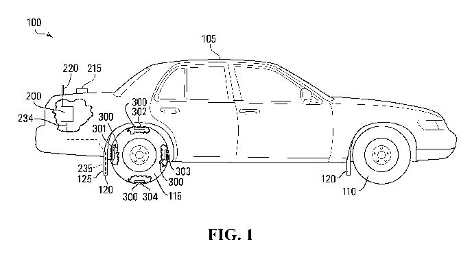
[0024] Figure 1 shows a vehicle positioning system 100 in a vehicle 105.
The vehicle 105
comprises a set of wheels 110, including at least one tagged wheel 115 that is
provided with a set
of affixable RFID devices 300. Each wheel 110 typically has a tire and in this
example, the
tagged wheel 115 comprises a tire 116 and the set of RFID devices 300 is
provided on the tire
116. The vehicle 105 also comprises mudguards 120, including an antenna
mudguard 125,
having an RF1D antenna 235 provided thereon. The vehicle positioning system
100 comprises a
controller 200, which in this example is a hardware device located in the
trunk of the vehicle
105, although it may be mounted or provided in the vehicle 105 in other ways.
[0025] The vehicle positioning system 100 employs dead reckoning, in this
case in
conjunction with a locating system, in this example a GPS system, to ascertain
a position, or a
change in position of the vehicle 105. Vehicle positioning uses available
information to establish
a location of a vehicle, a travel path or travel distance of a vehicle, a
vehicle speed, or a vehicle
displacement. In this particular example, the vehicle positioning system 100
ascertains a vehicle
location and in particular uses dead reckoning to derive a more accurate
location than is possible
with GPS alone as well as to track location when GPS service is unavailable
such as when the
vehicle 105 is in a tunnel, car parking lot, or otherwise outside of GPS
signal range.
5
CA 02976742 2017-08-15
WO 2017/096493 PCT/CA2016/051513
[0026] There are a variety of reasons for which it may be desired to
obtain a vehicle location
that is accurate to a degree higher than the precision of GPS. For example in
surveillance
vehicles that monitor parking violations, it may be desired to determine that
a parked vehicle has
remained in the same position for longer than a prescribed period of time. By
analysing images
of the parked vehicle's wheel positions, together with the parked vehicle's
precise location, at
two different times it may be determined with a great degree of certainty that
the vehicle has
remained unmoved. The position of the parked vehicle may be ascertained from
images of the
parked vehicle, however this requires precise knowledge of the camera's
position, which if
located on a surveillance vehicle requires precise knowledge of the
surveillance vehicle's
position. This is only one example of application requiring precise vehicle
location. GPS
systems, even augmented GPS systems, typically do not provide accuracy in the
range of
centimeters.
[0027] Vehicle positioning system 100 combines GPS data with accurate
travel data
determined using dead reckoning to derive a more accurate vehicle location
using a tightly-
coupled Kalman filter algorithm, which is used to determine vehicle location
based on weighted
averages of multiple sensor data inputs provided by the GPS, wheel ticks, and,
optionally, the
gyroscope 250. During times of good GPS signal reception, the measurements
from the vehicle
sensors are constantly calibrated. If late a situation with bad or no GPS
signal occurs, the system
continues to provide highly accurate location based on vehicle sensor inputs.
[0028] Dead reckoning data is data indicative of the movement of the
vehicle 105. In a
simple form, it may be simply travel distance data indicating a scalar value
as would be provided
by a typical vehicle odometer. Even simple travel distance may be useful for
improving GPS
location and even for ascertaining vehicle 105's location outside of GPS range
(e.g. in a tunnel),
the latter particularly so if geographical information can be used for map-
matching. In this
particular example, however, the vehicle positioning system 100 employs a more
sophisticated
system of dead reckoning which combines travel distance data with gyroscope
data (which
provides information on vehicle rotation/orientation), accelerometer data
(which provides
information on front-to-back and lateral acceleration) and compass data (which
provides vehicle
bearing information). In the present example, a three-axis gyroscope is used,
such that a
correctly-aligned yaw rate can be obtained even if the gyroscope 250 isn't
perfectly aligned.
Likewise the accelerometer is a three-axis accelerometer which can provide x-
axis (front to
6
CA 02976742 2017-08-15
WO 2017/096493 PCT/CA2016/051513
back) acceleration data but also be used to improve height estimation
accuracy. The compass
may be omitted.
[0029] As illustrated in Figure 2, the vehicle positioning system 100
comprises a controller
200. The controller 200 comprises hardware for performing vehicle positioning.
The controller
200 comprises a processing unit 205, memory 225, an RFID unit 230, a GPS unit
240, a wireless
communication unit 270, a gyroscope 250, an accelerometer 255, a compass 260,
a wireless
communication unit 270, a USB interface 280 and a Network Interface 285. The
illustrated
architecture is merely an example intended to provide the reader with a
working understanding
of the invention, however it should be understood that other architectures may
be used. For
example, in another embodiment a single global navigation satellite system
(GNSS) unit may
comprise the GPS unit, a three-axis gyroscope, and a three-axis accelerometer.
Moreover, the
USB interface connected to the processing unit 205 may be absent, but the GNSS
unit may have
a USB interface.
[0030] The processing unit 205 in this example comprises an ARM-based
microcontroller,
specifically in this case the microcontroller STM32F207VCT6Tm by STTm. The
controller 200
also comprises memory 225, shown here as a single unit for simplicity although
a skilled person
will understand the various configurations of memory possible. The memory 225
is a tangible
memory and comprises computer-readable instructions in the form of software
code executable
by processing unit 205 to cause the processing unit 205 to perform vehicle
positioning as
described herein. ln this particular example, the controller 200 has been
provided a general-
purpose microcontroller and software to perform vehicle positioning; this
configuration has been
chosen to provide design flexibility and to allow the controller 200 to be
programmed to perform
other functions. However, it is to be understood that the processing logic of
the controller 200
performing vehicle positioning may alternatively be provided by hardware
implementations such
as with an FPGA programmed to implement the logic described herein, or an ASIC
designed to
implement the logic described herein.
[0031] The GPS 240 unit is a standard GPS module that is in communication
with a GPS
antenna 245, which in this example is an off board antenna mounted on the
exterior of the
vehicle 105 for greater coverage. The GPS unit 240 derives from GPS signals
received by the
GPS antenna 245 GPS data which is communicated to the processing unit 205 in
this case using
asynchronous serial communication via a UART.
7
CA 02976742 2017-08-15
WO 2017/096493 PCT/CA2016/051513
[0032] The wireless communication unit 270 communicates information over
a wireless, e.g.
3G or WiFiTM, link using a wireless communication antenna 275, which in this
example is
provided separately. The wireless communication unit 270 communicates with the
processing
unit 205 to receive therefrom information to transmit and to provide thereto
information received
over the wireless communication link. This allows, e.g., cellular network
connectivity to allow
the controller 200 to provide vehicle positional information to a remote
device.
[0033] In this example, the processing unit 205 has onboard USB
communication capability
and is in communication with the USB interface 280 which provides a physical
link through
which a USB device can be connected. USB can be used to download data, e.g.
historical vehicle
positional information, to a IJSB storage and to upload data, e.g. new
software. Here again, the
architecture shown is only an example meant to provide the reader with command
of the
invention. Other architectures are possible and in an alternate embodiment,
the function of the
USB interface 280 may be provided via the network interface 285 or some
function may be
omitted. Likewise certain components such as the GPS unit 240 (or GNSS unit
described above)
and the wireless communication unit 270 may themselves have USE interface,
e.g. used for
debugging.
[0034] In this example, the controller 200 further comprises a network
interface 285, e.g.,
and Ethernet interface for communicating data, e.g. vehicle positional
information data or
software updates.
[0035] The controller 200 in this example further comprises physical
sensors including a
gyroscope 250, an accelerometer 255 and a compass 260. These provide
additional information
on the orientation of the vehicle and motion thereof which is used by the
processing unit 205 to
derive dead reckoning data
[0036] The RFID unit 230 communicates via a connected RFID antenna 235
with the tags of
set of RFID devices 300. The RFID unit is in communication with the processing
unit 205, in
this example via an SPI connection. The RFID unit 230 comprises an amplifier
231, a reading
unit 232 and a calibrating unit 233. In the present example, the RFID unit 230
comprises RFID
reader chip CLRC663TM by NXPTM. The RFID unit 230 is connected to the RFID
antenna 235
via an insulated coaxial antenna cable 234.
[0037] Although the controller 200 is a single hardware device in this
example, the controller
200 could be distributed. Moreover, the controller 200 need not include every
component shown
8
CA 02976742 2017-08-15
WO 2017/096493 PCT/CA2016/051513
here; some components may be absent or be provided externally outside of, and
in
communication with, the controller 200.
[0038] The RFID antenna 235 is mounted on the vehicle 105 in proximity to
the wheel 110,
preferably in the wheel well or adjacent thereto. The vehicle 105 comprises at
least one wheel
115 that is provided with the set of RFID devices 300, specifically in this
case in the tire 116.
The RFID antenna 235 is mounted in mudguard 125 so as to be within range to
read the RFID
devices passing in front of it as the tire 116 rotates. Advantageously, since
mudguards are
generally an easily replaced vehicle component, installing the RFID antenna
235 can be as easy
as replacing a standard mudguard with the antenna-bearing mudguard 125. The
mudguard 125 is
made of non-interfering material such as rubber, and preferably completely
encapsulates the
antenna 235 such that it cannot be seen from a casual observer's standpoint.
The antenna cable
234 protrudes from the mudguard 125 at a top end thereof inside the wheel well
such that it is
not visible from the perspective of someone who is standing near the vehicle.
Making the
antenna 235 invisible to casual observers protects the antenna 235 from
tampering of vandalism
ill-intending individuals who do not know it is there.
[0039] The RFID antenna 235 of this example is illustrated in Figure 4.
In this example, the
RFID antenna 235 is an ISO 1800-3M3 compliant antenna made of copper antenna
material 405
coiled in a rounded rectangular shape on a PCB board 410, although other media
may be used. In
this example the RFID antenna 235 is made in a coil having a rectangular form
with rounded
corners made up of two turns with has dimensions of 175mm x 110mm, although
dimensions of
150mm x 100mm have also been successfully used and other shapes and sizes may
be used. A
bigger antenna may increase reading distance but has the disadvantage of being
less adapted to
the mounting/wheel well dimensions. The RFID antenna 235 is characterized by
1.7p.F1 // 7.6pF
in this example. Passive components (resistors, capacitors) are used to tune
the RFID antenna
235 with the RFID frequency of 13.56MHz. Once the antenna is encapsulated,
e.g. in rubber, the
dielectric constant is changed by the presence of the encapsulating material
and therefore the
antenna is re-tuned to 13.56MHz by changing the passive components. Decreasing
the
inductance reduces the reading range. However increasing the inductance comes
at the price of
increasing the parallel capacitance which reduces reading performance.
Experimentally, it has
been found that an inductance of 1 ttH to 411H may work with 1.711H being
preferred. The
13.56MHz carrier signal is set to 4.5V peak-to-peak in a 50Q load. The source
of this carrier is
9
CA 02976742 2017-08-15
WO 2017/096493 PCT/CA2016/051513
the transmitter of the CLRC663. This carrier signal is then radiated from the
RFID antenna 235,
the amplitude of which will be slightly altered by RFID tag in proximity,
which change is
detected by the RFID reader. The input of the RFID reader has a voltage limit
of approximately
4V peak-to-peak to 4.5V peak-to-peak. Although the CLRC663 can be set to
output a signal as
high as 8V peak-to-peak, it has been found that if the amplitude is too high,
the diodes connected
at the RFID reader will limit the voltage which degrades the reading
performance. The RFID
antenna 235 receives the signal over the antenna cable 234 and comprises an
SMA connector
415 to connect thereto. In this example, the SMA connector is partly embedded
but sufficiently
protrudes to allow the cable to connect.
[0040] The RFID antenna 235 is mounted in the mudguard using rubber
encapsulation The
RFID antenna 235 may be provided in a plate or other plastic structure that
itself is encapsulated
in rubber. Alternatively, the RFID antenna 235 may be provided elsewhere in
the vicinity of the
wheel, and could be mounted elsewhere in the wheel well. It is preferable to
mount the RFID
antenna where there will be not too much variation in the spacing between it
and the wheel. For
example, if mounted to the top of the wheel well, the vehicle suspension
system will cause
significant variations of distance which can cause reading degradation. The
rubber itself may be
provided an embedded fabric (e.g. nylon) mesh to provide additional stiffness
to the rubber. In
the present example, the dimension of the rubber is of 14" x 11.25". Any extra
rubber can be
Folded and/or cut. Figure 6 shows one implementation where the RFID antenna is
mounted to the
wall of the wheel well itself In this example, the RFID antenna was protected
behind a rubber
shield bolted to the wheel well wall.
[0041] Although in this example, the RFID antenna 235 is mounted in the
mudguard, it is to
be understood that the RFID antenna 235 may be mounted elsewhere where it can
read passing
RFID devices so as to identify which RFID device is closest to it, e.g. by
being within range of
only one RFID device for portions of the RFID devices rotation on the wheel
115.
[0042] The wheel 115 comprises the set of RFID devices 300 which includes
in this example
four RFID devices, specifically a first RFID device 301, a second RFID device
302, a third RFID
device 303 and a fourth RFID device 304. Each of the tags in the set of RFID
devices are
provided in the tire 116, and specifically in this example on the interior of
the tire 116 such that
they are invisible from the outside. This not only protects the RFID devices
300 from exterior
CA 02976742 2017-08-15
WO 2017/096493 PCT/CA2016/051513
elements but also discourages tamper or vandalism by making them hard to
access and invisible
to individuals who don't know they are there.
[0043] The RFID antenna 235 is mounted on the vehicle, in this case on
the mudguard 125,
such that it can detect the RFID devices 300 as they pass in front of it so as
to allow the
controller 200 to compute a wheel rotation rate. The configuration of the RFID
antenna 235 and
the RFID devices 300, and their installation configuration is such that during
a full rotation of the
wheel 115, each of the RFID device 300 is the only one to be detected by the
RFID unit 230
using the RFID antenna 235 at a certain time. This allows the RFID unit 230 to
interrogate the
RFID devices 300 and on the basis of the detected RFID devices 300 the
controller 200 can
ascertain the sequence of the RFID devices 300 passing in front of the antenna
235
[0044] By knowing when each tag passes in front of the antenna 235, the
controller 200 can
compute the travel distance of the vehicle. In the present example, if there
are 4 tags installed
equidistantly along the periphery of the tire 116. The tire 116 has a
perimeter of 223 cm. Thus
the tags are roughly 56 cm apart measured along the periphery of the tire 116.
So if the RFID
unit 230 identifies successively the first RFID device 301 then the second
RFID device 302, then
the processing unit 205 can ascertain that the vehicle 105 has moved forward
approximately 56
cm. Moreover, where the set of RFID devices 300 comprise more than two tags,
the tag ID's in
the reading sequence can also be used by the processing unit 205 to observe
the direction of
travel.
[0045] Figure 3A illustrates one of the tags from the set of RF1D devices
300 from a top plan
view. Figure 3B illustrates the same tag from a cross-sectional view exposing
the RFID
technology inside. In this particular example, the RFID device 300 is made of
a two-part
construction, the lower part being shown in Figure 3B and a cap portion, shown
in Figure 3C,
which overlap the lower part on the surface shown in Figure 3B and is sealed
to it to create a
single piece with a (once sealed) unitary body 305.
[0046] In this particular illustration the first RFID device 301 is
shown, however in this
example all of the tags in the set of RFID devices 300 are made in the same
manner (although
they each have unique tag identifiers). The first RFID device 301 is an
affixable RFID device. It
comprises a unitary body 305 within which is embedded an RFID tag 310. The
RFID tag 310
comprises a tag antenna 315 and a tag chip 320 connected to the tag antenna
315 by being
soldered onto a small printed circuit board (PCB) which is connected to the
tag antenna 315.
11
CA 02976742 2017-08-15
WO 2017/096493 PCT/CA2016/051513
[0047] The tag chip 320 is a passive HF RFID chip. Advantageously, the
use of a passive HF
chip allows the creation of operation conditions whereby only one tag may be
read by the RFID
unit 230 at certain points in the rotation of the wheel 115. This may be only
a short amount of
time. For example, if the vehicle 105 can travel up to 200Km/h, then the RFID
devices 300 may
each be within the reading range of the RFID antenna 235 for only 10ms at a
time (17ms for
120Km/h). In order to maximize effectiveness, the present example provides an
incredibly low
reading time by enabling a fast data transfer rate with minimal data transfer.
This not only allows
reliable operation of the vehicle positioning system 100 at high vehicle
speeds but also provides
high reliability since the RFID unit 230 has the chance to read each of the
RFID devices 300
more than once during the time that they pass in front of the RFID antenna 235
during normal
operation of the vehicle. This allows a measure of redundancy in case a tag
reading operation
fails.
[0048] Testing has revealed that LF RFID tags provide data rates
(1Kbit/s, 4Kbit/s, 8Kbit/s,
and up) that are insufficient for this application. Testing also revealed that
UHF RFID tags,
which have adequate data transfer rates, are not suitable for vehicle
positioning using multiple
RFID tags in wheels because they are too susceptible to poor performance when
water, ice, dirt
and/or mud comes between or around them and the RFID antenna 235. Moreover,
since UHF
RFID readers are highly sensitive, they tend to pick up other tags in the area
making them
inadequate for vehicle positioning.
[0049] HF RFID comprises several subcategories. 1S015695 is a standard for
vicinity cards
which can be read from a greater distance as compared to proximity cards. This
standard features
a data rate of 26.48Kbit/s. Testing revealed that reading the 64 bit unique ID
from tags using this
standard takes around 6ms, which is inadequate for the vehicle positioning
system 100 to reliably
read tags at a vehicle speed of 120Km/h.
[0050] IS014443A/B is a standard for proximity cards used for
identification, and the
transmission protocols for communicating with it. It features a data rate of
106Kbit/s. This data
rate is adequate, however this standard requires a closer reading distance,
which was found in
one particular implementation to be of roughly 3 inches. This may be suitable
for other
embodiments, however, in this particular example, the mudguard 125 was
selected as a mounting
point for the antenna 235, which is at a greater distance than 3 inches from
the tire 116.
12
CA 02976742 2017-08-15
WO 2017/096493 PCT/CA2016/051513
[0051] IS018000-3M3 is a standard that shares a file structure like the
UHF standards and
the RF interface of a proximity card. It provides the advantage of great
reading
distance/performance while featuring high speed data rate similar to those
found in UHF tags.
This standard was selected in this example for the tag chip 320. Specifically,
the tag chip 320
uses 13.56MHz RFID technology under the 18000-3M3 standards. Data rates range
from
25Kbit/s to 100Kbit/s upload and 53Kbit/s to 848Kbit/s download. Specifically
in this example
the download speed (from the RFID tag 310 to the RFID unit 230) was set to
212Kbit/s which a
good signal noise ratio than the higher speed setting of 848Kbit/s, leading to
a greater probability
of successful reading. Upload speed (from the RFD) unit 230 to the RIFD tag
310) was set to
106Kbit/s.
[0052] The CLRC663 chip provides a command to read the tag in full, which
takes three
transactions between the reader and tag. This provides more information than
is required and
therefore takes more time than required. Steps are therefore taken to reduce
the read time. To
begin with, anti-collision, which determines how many tags are present at one
time within the
reader's field, is disabled since we never expect to have more than one tag in
the field. Tndeed in
this particular example, the read range is such that when one tag is present,
no other tags are
within the range. The EPC (electronic product code) which is a unique number
associated to each
tag has a bit length that can be set to a minimum length of 16 bits, however
in this example
determining the unique number is not required to identify a tag. The
controller 200 causes the
RFID unit 230 to send an interrogation signal to the RFID device 301,
whereupon the tag chip
320 receives the interrogation signal via the tag antenna 315 and provides
data in return by
transmitting it using the tag antenna 315. In a first transaction, the CRC
stored is read. In a
second transaction, the EPC is read. The third transaction of the read command
provides
information like the handle which are of no use for merely identifying which
of the RFID
devices 300 is being read.
[0053] In the present example, only the first transaction is used, which
reduces the read time
to around 1.2-1.5ms, although polling is done every 3ms. Reading the CRC
suffices to determine
which of the tags is currently proximate to the RFID antenna 235. The stored
CRC (cyclic
redundancy check) is a code that a tag calculates over its StoredPC and unique
item identifier
(UWEPC) and stores in the UII memory at power-up, that is when the tag enters
the RFID
reader's radiation field.
13
CA 02976742 2017-08-15
WO 2017/096493 PCT/CA2016/051513
[0054] Alternatively, only the third transaction may be omitted, for a
total of two
transactions, which yields in this example a reading time of around 3ms.
[0055] In the present example, in ideal conditions the RFID devices 300
may up to 4.33"
away from the RFID antenna 235 in the mudguard 125 when in position in front
of the RFID
antenna 235, and more specifically in this example they are 13 centimeters
apart.
[0056] In this particular example, RFID device 301 is a tire patch with
the RFID tag 310
embedded therein. The RFID device is mounted to the inside of the tire under
the crown (rather
than on the sidewall). Initial tests, however, indicated that existing RFID
tags and tire patch
technology does not work because the high stress placed on the patch, and on
the tag antenna
therein leads to the rapid fracture of the antenna material.
[0057] In the present example, the RFID tag 310 has a tag antenna 315
that has a coiled =
planar configuration, defining a closed shape, in this case a circle. The tag
antenna 315 of this
example has round coil of 100mm diameter with 3 or 4 coil windings (in this
example 4) of the
antenna material. Other coil geometries, e.g. square or rectangular tag
antennas may also be
used. Increasing the tag antenna size increases the possible reading distance
between the RFID
tag 310 and the RFID antenna 235, however the size is limited by the physical
space available
where the RFID device 301 will be mounted. In this case a diameter of 100mm
was chosen in
part due to the available space in the tire 116. The tag antenna 315 has
characteristics on average
of approximately 3.551.tH // 13pF and 23pF for the RFID chip that is connected
to the coil. When
the coil is 100mm diameter with 3 turns the inductance has been found to be
3.54 to 3.56uH and
more precisely 3.55uH. The capacitance of the coil has been found to be
between 14pf and 17pf.
Deviating from these preferred value, e.g. by increasing or decreasing the
number of turns, has
been found to cause a reduction in reading distance. In an alternate
embodiments, e.g. to fit into
smaller (e.g. narrower) tires, the tag antenna, made of beryllium copper, may
have a diameter of
50mm and a read distance of around 7cm from the RFID antenna 235. In yet
another alternate
embodiment, the tag antenna may be a 46mm x 78mm rectangular antenna and have
a read
distance of around 10 cm from the RF1D antenna 235. That said, brass coated
high carbon steel
has been found to be more physically resistant and better suited for use in a
tire.
[0058] The RFID tag 310 is embedded into a specialized tire patch 325,
having in this
example a 5 inch diameter, to form the RFID device 301. The RFID device
comprises a unitary
body 340 having a bottom surface 330 and a top surface 335. The bottom surface
330 has an
14
CA 02976742 2017-08-15
WO 2017/096493 PCT/CA2016/051513
outer periphery 345, which in this example has a rounded square shape although
other shapes
accommodating the RFID tag 310 are possible. The unitary body 340 is defined
between the
bottom surface 330, the top surface 335, in this example within the outer
periphery 345. The
RFPD tag 310 is embedded within the unitary body in a generally horizontal
plane within the
unitary body, the tag antenna 315 being generally coplanar with the horizontal
plane.
[0059] In the present example, the tire patch 325 is a two-part
construction made up of two
layers, namely a bottom layer, shown in Figure 3B and a top layer which forms
a cap portion
321, shown in Figure 3C. A circular groove 311 is provided in one of the two
parts, here in the
bottom layer, to receive the antenna. It has been found that immersing the
antenna in rubber
without an air gap decreases sensitivity and requires re-calibration and
overall has adverse effect
on performance. This has been found to be overcome by providing a passageway
for the antenna
in the form of groove 311. Two rubber gum (also known as chemical gum) patches
312, 313 are
provided on the bottom layer and corresponding rubber gum patches 322, 323 are
provided on
the cap portion 321, whereat the two layers are vulcanized together and thus
bonded, e.g. by the
application of vulcanizing fluid or heat. Alternatively, other suitable method
for embedding the
RFTD tag 310 may be used, such as placing it between two sheets of rubber that
are then bonded
together, however providing a groove 311 is preferred.
[0060] The unitary body 340 is a shallow body, meaning that it is
generally not tall so as to
stick out more than is reasonable for its application. In this particular
case, in a specialized tire
patch, the unitary body 340 is generally flat and has a thickness that is
generally less than 20mm
thick, and more particularly less than lOmm thick, and even more particularly
approximately
6mm thick.
[0061] Typical tire patches have a bottom surface that is entirely
vulcanized to the tire in
order to patch it. It has been found that embedding the RFID tag 310 into a
typical tire patch
causes stress on the RFID antenna 315 that causes fracturing of the RFID
antenna 315. Through
experimentation it was found that stress on the tag antenna 315 can be reduced
by vulcanizing
only a portion of the RFID device 301 to the tire. More specifically, the RFID
device 201
comprises an affixing portion 350 in the bottom surface 330 which is affixed
to the tire 116, in
this case by vulcanization. The RFID tag 310 tag antenna 315 is provided in
the unitary body 340
such that it does not overlap the affixing portion 350. The affixing portion
350 being affixed to
the tire 116 is subject to bending, compression and stretching, more generally
to deformation,
CA 02976742 2017-08-15
WO 2017/096493 PCT/CA2016/051513
with the portion of the tire 116 where it is affixed. The bottom surface 330
also comprises a non-
affixing portion 370 that is not vulcanized to the tire 116.
[0062] The unitary body 340 thus comprises an affixing body portion 355
which overlaps the
affixing portion 350 and is therefore subject to deformation therewith and a
floating portion 360,
which does not overlap the affixing portion 350 and may overlap the non-
affixing portion 370.
The floating portion 360 of this example overlays the tire around the affixing
portion 350. In this
particular example the affixing portion 350 forms a slight elevation of the
bottom surface 330 in
the downward direction. As a result a gap 365 may exist between the floating
portion 360 and the
tire 116 in some portions thereof, although in alternate embodiments the
bottom surface 330 may
be flat, leaving no gap. In further alternate embodiments, the bottom surface
330 may be
provided with a more pronounced downward extension towards or at the affixing
portion 350 to
raise the floating portion 360 further away from the tire 116, or may
similarly have an upwardly
projecting angle from the affixing portion 350 to raise the non-affixing
portion 370 away from
the tire 116. In one such example, the unitary body 340 has a generally
mushroomoid shape such
that the bottom surface 330 projects in a downward plateau at the affixing
portion 350 while the
non-affixing portion 370 is raised by the downward plateau away from the tire
116.
[0063] Although the floating portion 360 is not affixed to the tire 116,
in the present
example, it may still contact the (in this case, inner) surface of the tire
116 and rub thereagainst.
However, since the floating portion 360 is not affixed to the tire beneath it,
it is not forced to
necessarily deform with the tire underneath it. The floating portion 360 may
still be subject to
some deformation imparted onto it by deformation of the affixed portion 355,
although the
overall effect is a reduction of the stresses on the materials within the
floating portion 360.
[0064] In order to reduce the stress imparted on the RFID tag 310, and
more particularly on
the tag antenna 315, the RFID tag 310, and more particularly the tag antenna
315 is embedded
into the unitary body in the floating portion 360. In particular, the non-
affixing portion 370
surrounds the affixing portion 350 such that the floating portion 360
surrounds the affixing body
portion 355. The tag antenna 315 is provided in the floating portion 360
surrounding the affixing
body portion 355 and the affixing portion 350.
[0065] The affixing portion 350 can be of any shape or size sufficient to
firmly hold the
RFID device 301 to the tire 116. In this particular example the affixing
portion is a 50mm circle,
which has been found to provide sufficient bonding to the tire for a reliable
long-lasting
16
CA 02976742 2017-08-15
WO 2017/096493 PCT/CA2016/051513
adherence. The tag antenna 315 is generally centered about the affixing
portion 350, and being
that it antenna has a diameter of 100mm, it lies at a good distance from the
affixing portion 350,
namely in this case it lies no closer than around 25mm away at every point. As
a result,
deformation in the unitary body 340 resulting from deformation of the tire 116
is concentrated in
a single area away from the RFID tag 310 and the stress in the floating
portion is dissipated
radially such that little stress is absorbed by the RFID tag 310 and more
particularly the tag
antenna 315.
[0066] In this particular example, the unitary body 340 of the RFID
device 301 is generally
planar and the bottom surface 330 has a projection 375 at the affixing portion
350. The affixing
portion 350 may be affixed to the tire 116 by suitable affixing technology. In
this particular
example, the affixing portion 350 is vulcanized to the tire 116. The
vulcanization process used in
this example is a chemical vulcanization. For this purpose, the affixing
portion comprises a
chemical gum that reacts to vulcanization fluid when applied to it so as to
cause bonding with the
tire 116. The rest of the unitary body 340, or more particularly the rest of
the bottom surface 330,
including the non-affixing portion 370, does not comprise the chemical gum,
but rather cured
rubber, and thus does not bond to the tire 116 when the vulcanization fluid is
applied. In
particular, in this example, a rubber gum is applied to the center of the
unitary body 340 to create
the projection 375. This rubber gum reacts with the vulcanization fluid to
adhere to the tire 116.
The projection 375 in the bottom surface 330 raises the non-affixing portion
370 away from the
tire, as described here, which has the effect of further isolating the
floating portion 360 from the
tire 116 and further reducing deformation of the floating portion with the
tire 116.
[0067] In alternate embodiments, other means of adhesion of the RFID
device 301 to the tire
116 may be selected, provided that they provide sufficient adherence. Certain
adhesive may be
suitable. Some adhesives have been tried with reasonable success, although
their cure times were
longer than vulcanization and they did not perform as well as vulcanization.
Moreover
vulcanization fluid is widely available and can be found at most mechanics,
thus providing
another advantage.
[0068] Typical RFID tags may be made with copper antennae. This material
is generally
selected for its favorable electrical characteristics. However, it has been
found that copper is ill-
suited for the high-stress environment of the tire 116. Even with the tag
antenna 315 being
embedded in the floating portion 360 of the unitary body 340, the tag antenna
315 is subject to
17
CA 02976742 2017-08-15
WO 2017/096493 PCT/CA2016/051513
some stress from deformation that can cause fracture or breaking of the
antenna on the long run.
For this reason, different materials, not typical of RFID antennae have been
experimented with.
It was found that materials having a minimum tensile strength of over 100KPSI,
and preferably
110KPST or more, and preferably still 150KPSI or more provided the long-term
longevity
performance, with even better long-term longevity performance with higher
tensile strengths of
398. 8KPS1-442.2KPSI.
[0069] Through experimentation with various materials, it was found that
Beryllium Copper
provides a respectable performance for long-term durability. Specifically,
Beryllium Copper
Alloy 25 CDA 172 was used, which has a minimum tensile strength of 150KPSI.
Rather than
providing the tag antenna 315 on a rigid board, Beryllium Copper wire of
0.010" was used,
insulated with VG Bond Coat and coiled on a brace while current is run through
the wire to heat
it up. The tag antenna 315 so created is then soldered to the tag chip 320 and
is embedded
directly into the unitary body 340.
[0070] Through further experiment an even more preferable antenna
construction has been
found, specifically hose wire made of brass coated high carbon steel at
0.250mm (0.010'), which
has a tensile strength of 2750-3050N/mm2 or 398.8KPSI-442.2KPSI. The wire is
insulated with a
heavy coat of PAC-240 polyimide wire insulation and Bond El, which is a
thermoplastic
modified epoxy bond coat. With the polyimide, the overall wire diameter is of
approximately
0.2946mm (0.0116"), while with the Bond El the diameter is approximately
0.3353mm
(0.0132"). Heat or chemicals may be used to bond the wires together; Bond El
reflows at 130 C.
In order to protect the wire and keep it intact, a last layer of epoxy is
applied. Embedding the tag
antenna with epoxy allows it to keep its shape under the high stresses applied
by the tires in
movement. This coil is then placed the rubber patch groove 311 as described
above.
[0071] Other materials for the tag antenna 315 are possible. Carbon fiber
may have the
required strength, however it is particularly difficult to solder. Phosphor
Bronze has been used
with some success. Phosphor Bronze has a minimum tensile strength of 110KPSI
and performed
adequately for a certain duration, albeit not necessarily the lifetime of the
tires.
[0072] The tire 116 comprising the RFID devices 300 is a novel tire that
provides new
functionality including the ability to do vehicle positioning using the
vehicle positioning system
100. In the example provided herein, the RFID device 301 (which is similar to
all the other RFD)
devices 300), is provided as an affixable patch. Advantageously, this makes it
possible to install
18
CA 02976742 2017-08-15
WO 2017/096493 PCT/CA2016/051513
it into any tire for any vehicle, or at least any tire for which the patch is
properly dimensioned. In
an alternative embodiment, however, the RFID devices 300 may be built into the
tire at
manufacture, either by being affixed thereto at manufacture or by being molded
as part of the
tire. In the latter case the affixing portion of the bottom surface is in fact
bonded by unitary
construction with the rest of the tire.
[0073] While in the illustrated example, the tire 116 was provided four
RFID devices 300, in
alternate examples, more or fewer may be used. Naturally, varying the number
of RFID devices
300 varies their distances and the controller 200 must take the distance
between RF1D 300 into
account when computing vehicle positioning. Moreover, although in the present
example the
RFID devices 300 are equidistant from one another along the periphery of the
tire 116, in
alternate embodiments they may not necessarily be so. In such cases, the
controller 200 may take
into account the distance between RFID devices 300 to compute positional
information. The
controller 200 may be configured to perform a calibration, whereby the tire
116 is rotated by
known amounts, and the amount of rotation is provided to the controller 200 to
allow the
controller 200 to count the distance between RFID devices 200.
[0074] For simplicity, only one RFID antenna 235 and only one tire 116
with RFID devices
300 was shown in this example. However, this system may be replicated for
other wheels 110 of
the vehicle 105. To this end, the controller 205 may have multiple RFID units
230 to detect
rotation of' multiple wheels 110. This may provide a measure of' redundancy,
particularly at high
speeds when tag misreads may be more common. The present system is already
resistant to some
tag misreads, since it can interpolate positional information even in the
absence of a certain
number of tag reads, but providing redundancy can provide it even greater
precision.
[0075] In the present example, the controller 200 merely uses RFID unit
230 to read the tags
in the RFID devices 300. The tag IDs read by the RFID unit 230 allow the
controller 200 to track
to movement of the vehicle. By knowing the distance between RFID devices 300
and knowing
their order on the wheel 115, the controller computes a change is position on
the basis of the
distance between RFID devices 300. E.g. if the tags are 56 cm apart, and RFID
device 302
follows RFID device 301, and that the RFD unit 230 reads these tags in order,
the controller 200
ascertains that the vehicle 105 has moved forward by 56 cm.
[0076] However, in alternate embodiments, the RFID unit 230 may also
perform writing
operations to the RFD tags in the RFID devices 300. This is particularly
possible where the tire
19
CA 02976742 2017-08-15
WO 2017/096493 PCT/CA2016/051513
116 is used in a low-speed environment, or where the transfer rate between the
RFID unit 230
and the RFD devices 300 is high, e.g. if the distance between the RFID antenna
235 and the
RFID devices 300 is reduced or if higher ¨throughput protocols are used. In
such cases, the
controller 200 may provide information into the RFID devices 300 e.g. for
tracking purposes. In
one example, the controller 200 may implement a turn-counting method whereby a
count value
is incremented in the RFID tag of each RFID device 300 at every turn. In this
manner, the RFID
devices 300 may be used as a type of tire odometer, counting the wear put on a
tire. In a variation
on this design, each of the RFID devices 300 may begin with a count that
differs by a value (e.g.
1) and they may each be incremented by a non-overlapping amount (e.g. by the
number of tags,
in this case 4). The count value, being that it will necessarily always have
the same modulus of 4
(in this example), can serve as a tag ID. In this example, a count of 1, 5, 9,
13, etc... would
indicate RFID device 301; a count of 2, 6, 10, 14, etc... would indicate RFID
device 302; a count
of 3, 7, 11, 15, etc... would indicate RFID device 303; and a count of 4, 8,
12, 16, etc... would
indicate RFID device 304. When the controller reads an RFID device, it stores
the count value at
least until it reads the following one. It then verifies whether the following
RFID device has the
right count value, or if it was the subject of a misread/miswrite at the last
rotation. If it was, the
controller commands an increment by the appropriate amount to correct the
value. In this manner
a misread/miswrite-resistant tire odometer may be implemented.
[0077] Although in the examples provided herein the controller 200 was
implemented as a
separate device, it will be understood that in an alternate example where the
vehicle 105
comprises suitable hardware in its onboard computer, the controller 200, or
parts thereof, may be
implemented by the onboard computer. In one example, the RFID unit 230 is
provided to the
vehicle 105 and placed in communication with the onboard computer that is
reprogrammed to
perform the function of the controller 200.
[0078] As described herein is provided a vehicle positioning system for
determining the
position of a vehicle. The vehicle positioning system may comprise an RFID
antenna mount, for
example mudguard 125, configured for mounting an RFID antenna on the vehicle
in proximity to
a wheel having a tire. The mudguard 125 may comprise any standard mudguard
attachment
means. The vehicle system also comprises an RFID antenna for mounting on the
RFID mount.
For example the RFID antenna 235 comes pre-mounted in the mudguard 125 by
being embedded
therein, e.g. by being molded therein. The antenna is configured for
communicating with a
CA 02976742 2017-08-15
WO 2017/096493 PCT/CA2016/051513
proximate RFID tag located in the wheel, and more particularly in the tire, in
proximity to the
RFID transceiver to interrogate the proximate RFID tag and to detect a return
signal indicative of
a tag identifier associated with the proximate RFID tag. The vehicle
positioning system
comprises a controller configured for communicating with the RFID antenna to
cause the
interrogating of the proximate RFID tags and to receive the return signal The
controller is
configured to determine, at least in part on the basis of a return signal and
a previously-received
return signal, a position of the vehicle. The controller is also configured
output an indication of
the position of the vehicle. The indication of the position of the vehicle may
be provided in any
of a number of ways. Where the controller 200 acts as an improved GPS system,
the position
information may be provided visually on a screen (not shown) as would be
typically done by a
GPS system. Alternatively or additionally, the positional information may also
be provided over
the wireless communication unit 270, USB interface 280, or network interface
285.
[0079] The controller may be configured to compute a reckoned distance of
travel by
performing dead reckoning whereby the reckoned distance of travel is based on
the distance
between the most recently (proximate) RFID tag and a previous RFD tag. More
specifically, the
reckoned direction of travel may be found by determining a rotation of the
tire that was
undergone between receiving the return signal and a previously-received return
signal from the
previous RFID tag. In particular, using dead reckoning the controller 200 can
consider the
distance between the latest and previous tag reads to be the distance between
the tags on the
periphery of the tire 116.
[0080] The different RFID tags may have unique identifiers provided with
their return
signals and the controller 200 may ascertain the reckoned distance of travel
based on the number
of successive return signals received and a distance separating the RFID tags
associated with the
return signals. The controller 200 may take into account the previous tag
identifier and ascertain
a distance travelled based on the current and the previous tag identifier
received, thus accounting
for a misread if one tag identifier was skipped. On the basis of the current
and previous tag
identifier, the controller 200 may also determine the direction the vehicle is
moving, provided
that more than 2 tags are provided on the tire.
[0081] The position determined by the controller 200 may be a relative
position, the
controller 200 only determining a distance of travel, or the position may be
absolute. For
21
CA 02976742 2017-08-15
WO 2017/096493 PCT/CA2016/051513
example the controller 200 may be configured to determine the position of the
vehicle on the
basis of GP S position data and the reckoned distance of travel of the
vehicle.
[0082] Although various embodiments have been illustrated, this was for
the purpose of
describing, but not limiting, the present invention. Various possible
modifications and different
configurations will become apparent to those skilled in the art and are within
the scope of the
present invention, which is defined more particularly by the attached claims.
22