Note: Descriptions are shown in the official language in which they were submitted.
CA 02976834 2017-08-16
WO 2016/131110 PCT/AU2016/050115
1
Firefighter Training Unit
Technical Field
[0001] The present invention relates generally to equipment for training
fire
fighters and more particularly to firefighter training equipment that
simulates real world
conditions experienced by fire fighters in hazardous environments.
Background of Invention
[0002] Firefighter training is typically an expensive and potentially
dangerous task.
Often the realism experienced in a training environment is significantly
limited due to
the inability of an instructor to recreate fire activity in a safe manner.
[0003] Expensive hot fire training props are often in high demand and are
limited
to recreating the one scenario that they were developed for. Firefighter
training is
therefore limited in the variety of different scenarios that can be presented
to trainee
firefighters so that the value of training can diminish as the trainee becomes
accustomed to the scenario that has been created. Such props also require the
use
of training vehicles, known as 'pumpers', to supply water to the training
area, so that
overall, significant man power is required to provide training opportunities
to the fire
fighters who are at the front line nozzles of firefighting equipment.
[0004] The use of breathing apparatus for front line fire fighters in an
internal,
structural fire fight, combined with dragging a hose line, carrying break and
entry gear
and other firefighting tools is made significantly more complex by the
addition of
smoke, fire activity and potential full structural collapse. The physical
exertion and
exhaustion felt by the firefight after a period of activity cannot often be
experienced in
a training environment.
[0005] There currently exists a need to develop firefighter training
equipment that
is relatively low cost, easy to deploy and adaptable to a number of training
environments which nevertheless provides a high degree of realism in order to
optimise the simulation experience. It would also be desirable to provide
training
equipment that ameliorates or overcomes one or more disadvantages or
inconveniences of known firefighter training equipment.
CA 02976834 2017-08-16
WO 2016/131110 PCT/AU2016/050115
2
Summary of Invention
[0006] One aspect of the present invention provides a fire fighting
training unit for
simulating use of a fire extinguishing system that includes a hose and a
liquid spray
outlet connected to one end of the hose, for dispensing a fire extinguishing
liquid, the
firefighting training unit including
a reel;
a user-manipulable nozzle;
a flexible and elongate member having opposite ends attached respectively to
the
reel and the nozzle and being at least partially wound about the reel, wherein
rotation
of the reel in a first rotational direction allows the elongate member to be
unwound
from the reel;
a motor configured to drive the reel in a second rotational direction,
opposite to the
first rotational direction which causes the elongate member to be wound onto
the reel;
one or more devices for providing one or more output signals corresponding to
one or
more simulated operating conditions of the fire extinguishing system; and
a controller configured to drive the motor in response to the one or more
output
signals so as to apply torque to the reel in the second rotational direction
to simulate
forces applied to the hose during operation of the fire extinguishing system.
[0007] In one or more embodiments, a first operating condition is liquid
flow rate
through the nozzle, and a first device is a flow rate selector for selecting
the liquid flow
rate.
[0008] In one or more embodiments, a second operating condition is liquid
spray
pattern, and a second device is a liquid spray pattern selector for selecting
the liquid
spray pattern.
[0009] In one or more embodiments, a third operating condition is nozzle
actuation to dispense a fire extinguishing liquid, and a third device is a
nozzle
actuation detector.
CA 02976834 2017-08-16
WO 2016/131110 PCT/AU2016/050115
3
[0010] Conveniently, any one or more of the above mentioned devices may be
fitted to the user manipulable nozzle.
[0011] In one or more embodiments, a fourth operating condition is
rotational
unwinding of the reel, and a fourth device is a rotational speed detector for
detecting
the rotational unwinding speed of the reel. Conveniently, the detector may be
an
encoder coupled to the reel.
[0012] In one or more embodiments, the torque caused to be applied to the
motor
by the control is dependent on configuration data accessible by the
controller. This
configuration data may include any one or more of:
fluid pressure, elongate member construction, elongate member length, floor
surface
and maximum force.
[0013] In one or more embodiments, a fifth device is mounted to the nozzle
for
capturing image data during use of the firefighter training unit.
[0014] In one or more embodiments, the elongate member is a flexible hollow
tube, and may be made from canvas, plastic, rubber or other material typically
used in
the construction of firefighting hoses.
[0015] In one or more embodiments, the firefighter training unit further
includes
electrical cabling extending within the tube between the one or more devices
and the
controller, for the purpose of transmitting data between the one or more
devices and
the controller.
[0016] In one or more embodiments, the fighting training unit may further
include a
fluid supply, and at least one inflation device coupled to the fluid supply
for inflating at
least a portion of the tube to simulate pressurisation of the hose of the fire
extinguishing system. Conveniently, the fluid supply may be a pressurised air
container. In this case, the inflation device may be, for example, an air line
extending
within at least a portion of the tube.
[0017] In one or more embodiments, the firefighter training unit includes
one or
more clamps to clamp the unit to a support surface, such as a floor.
4
[0018] In one or more embodiments, the controller may include a processor
and a
non-transitory computer readable medium storing program instructions to cause
the
processor to compute the torque to be applied to the motor and to apply that
computed torque.
[0019] Another aspect of the invention provides a method of operating a
firefighter
training unit, the method including the steps of:
receiving one or more output signals from the one or more devices, the output
signals
corresponding to one or more simulated operating conditions of the simulated
fire
extinguishing system; and
driving the motor in response to the one or more output signals so as to apply
torque
to the reel in the second rotational direction to simulate forces applied to
the hose
during operation of the fire extinguishing system.
[0020] The fighting training unit can comprise a base station at which the
reel, the
motor and the controller are located and from which the elongate member and
nozzle
can be unwound from the reel. The base station can further include the fluid
supply
and the inflation device if provided.
[0021] The motor can be an electric motor, AC or DC, or it can be a petrol
or
diesel motor.
Brief Description of Drawings
[0022]Preferred embodiments of the present invention will now be described by
way
of non-limiting examples only with reference to the accompanying drawings in
which:
Figure 1 is a perspective front view of a firefighter training unit according
to one
embodiment of the present invention;
Figure 2 is a perspective side view of the firefighter training unit of Figure
1;
Date Recue/Date Received 2022-11-17
CA 02976834 2017-08-16
WO 2016/131110 PCT/AU2016/050115
Figure 3 is a schematic diagram of the firefighter training unit of Figures 1
and 2 and
depicts further details of an elongate member and user-manipulable nozzle
forming
part of that firefighter training unit;
Figure 4 is a schematic diagram sensors and servo control circuitry used to
control
operation of a servomotor connected to a hoses reel and air compressor forming
part
of the firefighter training unit shown in Figures 1 to 3;
Figure 5 is a flow chart depicting various data processing steps performed by
a
controller forming part of the servo control circuit depicted in Figure 4; and
Figure 6 is a perspective view of firefighter training unit shown in Figures 1
and 2
when in use during firefighting simulation activities by a user.
Detailed Description
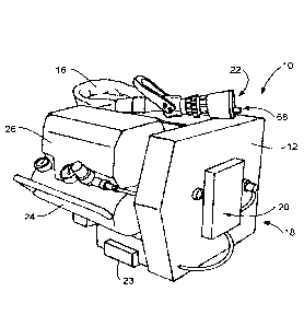
[0023] Referring now to Figures 1 and 2, there is shown a firefighter
training unit
for use in training firefighters in simulated hazardous conditions. The
firefighter
training unit 10 includes a housing 12 in which is mounted a reel 14. A
flexible hose
16, or other flexible hollow tube or other flexible elongate member is wound
around
the reel 14. In the embodiment depicted in Figures 1 and 2, the hose is made
from
material identical to hoses typically used by firefighters in extinguishing
fires.
However, in this embodiment water or other fire extinguishing fluid is not
required to
be pressurised within and expelled from the hose, and therefore in other
embodiments of the invention different hollow or solid elongate members may be
used.
[0024] The firefighter training unit 10 further includes a motor 18
configured to
drive the reel 14 in one rotational direction as well as a servo control
circuitry 20
configured to drive the motor 18. The firefighter training unit 10 also
includes a user
manipulable nozzle 22 attached or fixed to one end of the elongate member 16.
[0025] Depending on the environment in which it is used, it will be
convenient to
clamp the firefighter training unit 10 to the support surface upon which is
rests by
CA 02976834 2017-08-16
WO 2016/131110 PCT/AU2016/050115
6
means of magnetic clamps 23 or like fixation devices in order to prevent
lateral
movement of the firefighter training unit 10 during simulation.
[0026] The firefighter training unit 10 also includes a container 24 of
pressurised
air as well as a compressor 26. As can be best seen in Figure 3, in this
exemplary
embodiment an airline 28 extends within the hollow space inside the hose 16
between
the nozzle 22 and reel 14.The pressured container 24 and compressor 26 act to
supply pressurised air to the interior of the hose 16 to inflate the hose
during
firefighting simulations. In that regard, the airline 28 may include a series
of apertures
(not shown) running along its length in order to enable the pressurised air to
be
expelled from the airline to the interior of the hose 16.
[0027] The firefighting training unit 10 also includes one or more devices
for
providing one or more output signals corresponding to one or more simulated
operating conditions of the simulated fire extinguishing system.
[0028] One or more of these devices may be user operable selectors for
selecting
the liquid flow rate, desired spray pattern of water or other fluid to be
expelled from
the simulated fire extinguishing system. In addition, one or more of the
devices may
detect another user action, for example, user actuation of a gate valve
located on the
nozzle 22 to expel liquid. In a real world fire extinguishing system, user
actuated
movement of a gate valve (see the gate valve 34 of Figure 3) from a closed to
an
open position will cause water to be expelled from the hose of the fire
extinguishing
system.
[0029] Conveniently, such devices are mounted in the exemplary embodiment
shown in figures 1 to 3 on the nozzle 22. Both the flow rate selector 30 and
the spray
pattern selector 32 can be formed from rings mounted around the barrel of the
nozzle
22 with encoders or industrial analogue potentiometers attached to the rings
so as to
detect the angular position in which each ring is placed by an operator. The
gate
valve position detector 40 (see Figure 4) can be a simple switch housed within
the
nozzle 22 and operable when the gate valve 34 or like mechanism is moved in
the
direction of the arrow 36 from an off to an on position. Electrical cabling 38
extends
within the hose 16 between the spray pattern selector 32, flow rate selector
30 and
gate valve position detector 40,and the controller 20 for data transmission.
CA 02976834 2017-08-16
WO 2016/131110 PCT/AU2016/050115
7
[0030] As can be seen in Figure 4, the spray pattern selector 30 and flow
rate
selector 32 provide output signals corresponding - respectively to the spray
pattern
selected by an operator and the flow rate selected by an operator - to a
controller 39.
The gate valve position detected by a gate valve position detector 40 is
provided as
another output signal to the controller 39. A dead man switch or other
actuation
detector 42 may also be included in the nozzle 22 to provide a further output
signal to
the controller 38, in this case being indicative of the grasping of the nozzle
by a user.
[0031] As can be also seen in Figure 4, the motor 20 is connected to a hub
42 of
the reel 14, the hose 16 being wound around that hub 42. Operation of the
motor 20
is controlled by current from a servo amplifier 42, which is in turn
controlled by the
controller 39. An encoder 46 is coupled to the motor 20 to provide a position
feedback
signal to the controller indicative of the rotational speed of the reel, to
the controller
39. In that regard, a counter 48 is provided as part of the controller 39, the
frequency
with which pulses are received from the encoder 46 being indicative of the
rotational
speed of the reel 14.
[0032] In one or more embodiments, a dynamic load 47 may be coupled to the
motor 20 to restrict of the elongate member 16 out of the reel 14. The dynamic
load
47 assists in the delivery of step up or advancement forces at the hardware
level and
reducs the likelihood of damage to the electronics if a user pulls too fast on
the
elongate member 16, which would otherwise create a generator-like effect that
could
introduce damaging voltages into the system. The dynamic load 47 may include a
resistance connected in shunt across the motor 20.
[0033] Similarly, the air compressor 26 is coupled to one end of the hose
16 in
order to pressurize air within the airline 28 and thereby inflate the hose 16.
The air
compressor 26 is controlled by current from a servo amplifier 50, which is in
turn
controlled by the controlled by the controller 39.
[0034] Input/output circuitry 52 is provided as part of the controller 39
in order to
receive the output signals from the gate valve position detector 40, flow rate
selector
32, spray pattern selector 30 and handle actuation detector 42. In addition, a
digital
communication link 54 is provided as part of the controller 39 in order to
send control
signals to the servo amplifiers 44 and 50.
CA 02976834 2017-08-16
WO 2016/131110 PCT/AU2016/050115
8
[0035] The controller 39 includes a processor 56, read only memory or other
non-
transitory computer readable medium 58 storing program instructions to cause
the
processor to perform various computations described herein and to generate
control
signals to be transmitted to the servo amplifiers 44 and 50 from the digital
communication link 54. In performing its various operations, the processor 56
uses
data stored in a volatile memory 60, including configuration data 62 and one
or more
look up tables 64.
[0036] It will be appreciated that the gate valve position detector 40,
flow rate
selector 32, spray pattern selector 30, handle actuation detector 42 and
encoder 46
and merely examples of devices that may form part of the firefighter training
unit 10 to
provide one or more output signals corresponding to one or more simulated
operating
conditions of a real world fire extinguishing system.
[0037] Another exemplary such device is a camera 66 (best seen in Figure
6),
that may be conveniently mounted to the nozzle 22, which provides an output
signal
to the controller 39 corresponding to images captured from the environment
surrounding the firefighting training unit. This captured image data together
with other
data from the various devices forming part of the firefighter training unit 10
(such as
the selected spray pattern) may be provided to a virtual reality system for
incorporation into a display presented to a firefighter undergoing training in
order to
provide a more immersive training experience. As is the case with the
detectors 32,
30, 40 and 42, a connection between the nozzle mounted camera 66 and the
controller 39 may be provided by means of the electrical cable 38 extending
between
the nozzle 22 and the controller 38 inside the hose 16.
[0038] Other exemplary devices include an inertial measurement unit 67 and
infra-
red tracking unit 69. The inertial measurement unit 67 includes using a
combination
of accelerometers and gyroscopes, and possibly magnetometers, to track the
pose
and orientation of the user manipulable nozzle 22 during simulation so that an
accurate representation of a jet of water coming from the user manipulable
nozzle 22
can be generated by a virtual reality system.
[0039] The infra-red tracking unit 69 includes a head with infra-red
reception and
transmission capacities. Such a unit enables a trainer to use simple active
markers on
CA 02976834 2017-08-16
WO 2016/131110 PCT/AU2016/050115
9
walls or other surfaces in a training environment, for example, to
differentiate different
types of fires.
[0040] In some embodiments, rather than relying upon the electrical cable
38,
wireless transmission/reception devices 71 and 73 may be provided to enable
communication between the controller 39 and the various nozzle-mounted
devices.
[0041] In use, when a user grasps the nozzle 22 and moves away from the
firefighter training unit 10, the force applied by the hose 16 to the reel 14
causes
rotation of the reel 14 in one rotational direction so as to unwind the hose
from the
reel. The controller acts to drive the servo motor 20 in response to the
various output
signals received at the controller 39, taking into account configuration data
(defining
operational parameters of a fire extinguishing system to be simulated and
various
other parameters that may be required) to apply to torque to the reel 14 in
the
opposite rotational direction thereby to simulate the sum of one or more
forces
applied to the hose 16 during operation of the real world fire extinguishing
system.
[0042] Figure 5 depicts a flow chart showing various steps performed by the
controller 39 in the computation and application of a suitable torque to the
reel 14 in
order to simulate the sum of those various forces applied to the hose of the
real world
fire extinguishing system. After the firefighter training unit 10 and
controller 38 are
enabled at step 80, the controller 39 initially accesses configuration data
62, at step
82. The configuration data 62 may include any one or more of fluid pressure,
hose
construction, hose diameter, hose length, floor surface properties (in order
to
determine a frictional force that may be experienced by a firefighter) and a
maximum
force/torque that may be generated by the servo motor 20 as a safety
parameter.
[0043] This configuration data 62 can be set up via an operator control
panel (not
shown). All selections can be made from one or more different groups groups of
configuration data in order to simulate different types of fire extinguishing
systems.
[0044] At step 84, the controller 39 interprets the presence of a
firefighter by
detecting handle actuation from an output signal provided by the dead man's
switch
42. When handle actuation is detected the controller 39 acts at step 86 to
cause the
air compressor 36 to inflate the hose 16 by means of the airline 28.
CA 02976834 2017-08-16
WO 2016/131110 PCT/AU2016/050115
[0045] Before determining the value of the torque to be applied to the reel
14, the
controller 39 firstly detects the position of the encoder or industrial
analogue
potentiometer forming part of the spray pattern selector 30 fitted about the
nozzle 22,
as well as the position of the encoder or analogue potentiometer of the flow
rate
selector 32 which is also fitted about the nozzle 22 (step 88). Once these two
selections have been made at step 88, the controller 39 accesses information
stored
in the look up table 64 and, at step 90, computes a jet reaction force (also
called
nozzle reaction force) that would be applied to the nozzle of a real fire
extinguishing
system.
[0046] In addition, at step 92, the controller 39 determines whether the
firefighter
holding the nozzle 22 is moving away from the reel 14. If this is the case,
the
controller 38 access the look up table 64 to determine the dragging( set up)
force that
would be required to drag a full hose over a floor surface of the type
identified by the
configuration data at step 94. Once the jet reaction force 90 and the drag/
friction
force 94 have been computed, these two forces are summed by the controller 39,
and
signals sent to the servo amplifier 44 in order to cause the servo motor 20 to
apply a
torque to the reel 14 in the opposite rotational direction to that caused by
the
firefighter moving away from the reel 14, at step 96.
[0047] When the firefighter stops, and the controller 39 detects from the
pulses
provided by the encoder 46 that the reel rotational velocity has reduced to
zero, the
controller 38 will remove the drag/friction force computed at step 94 from the
force
applied by the motor 20.
[0048] It will be appreciated that the flow rate and spray pattern selected
will have
an effect on the jet reaction force calculated. In simple terms, a directional
jet of fluid
will generate more jet reaction force than will a fog or more dispersed spray
pattern,
whilst a higher flow rate will provide more jet reaction flow rate than a
lower flow rate.
A higher pump pressure (part of the configuration data) will also affect the
jet reaction
force, a higher pressure generating more force. A larger hose diameter will
also allow
for higher flow rates which will also affect the calculation of the jet
reaction force.
[0049] in various embodiments, a supervisory computer 100 may be connected
by USB, Ethernet, wireless or other suitable connection means to the
controller 20 to
CA 02976834 2017-08-16
WO 2016/131110 PCT/AU2016/050115
11
enable a trainer to control the real-time experience of a user of the
firefighter training
unit 10.
[0050] Finally it is to be understood that various modifications and/or
additions
may be made the above described embodiments without departing from the spirit
or
ambit of the invention as defined in the claims appended hereto.