Note: Descriptions are shown in the official language in which they were submitted.
CA 02976886 2017-08-16
PCT/JP2016/053409 1 /
38
DESCRIPTION
TITLE OF INVENTION: LOWER-SIDE SPRING-RECEIVING MEMBER
TECHNICAL FIELD
[0001]
The present invention relates to a lower-side spring-receiving member.
BACKGROUND ART
[0002]
Generally, when a spring load is applied on a spring-receiving member for a
suspension spring formed of, for example, an elastic material, a deformation
of the
spring-receiving member cannot sufficiently follow a deformation of the
suspension
spring, which causes a gap to be formed between the suspension spring and the
spring-receiving member.
[0003]
If foreign matter such as sand or gravel enters the gap formed in such a
situation,
coating film of the suspension spring may wear out to cause a base surface of
the
suspension spring to be exposed, resulting in an occurrence of corrosion and
breakage of
the suspension spring. This phenomenon occurs more frequently around a lower-
side
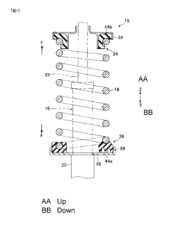
spring-receiving member than an upper-side spring-receiving member.
[0004]
PTL1 describes "an elastic sheet that can prevent a coil spring from, for
example,
being chipped in its coating or being broken as a result of the entry of mud,
sand, or the
like" (see the summary and paragraph [0030] of PTL1 (paragraph 0034 of US
corresponding application).
CITATION LIST
Patent Literature
[0005]
CA 02976886 2017-08-16
PCT/JP2016/053409 2
/ 38
PTL1: Japanese Patent Application Publication No. JP2014-199134A (US
corresponding application US2014-265081A1)
SUMMARY OF INVENTION
Technical Problem
[0006]
A spring-receiving member (rubber pad) described in PTL1 includes a
spring-receiving-side recess portion (a second recess portion) both in an
embodiment
and its modification example (see FIGS. 8, 17, 22, 24, and 26 of PTL1). This
second
recess portion is provided for a purpose of preventing a back surface of a
seating portion
right under the coil spring from being damaged due to contact with a mounting
surface
of the spring-receiving member (see paragraphs 0072, 0120, 0123, and 0125 of
PTL1).
[0007]
Such a conventional spring-receiving member may have a recessed volume of the
recess portion increased, which may impair followabiliy to the suspension
spring.
Specifically, there is a problem that the spring-receiving member cannot
sufficiently
follow the deformation of the suspension spring when the spring-receiving
member
returns from a compressed state to an original state. This causes a problem
that foreign
matter such as sand and gravel enters the gap to cause corrosion and breakage
in the
suspension spring.
[0008]
Further, for example, a lower-side spring-receiving member described in FIG. 8
of
PTL1 has a large recessed volume of the recess portion, and therefore, a
magnitude of
reaction force that the spring-receiving member can apply on the suspension
spring is
small as shown by a thick solid line in a graph of a comparative example (III)
of FIG. 7A
of the present disclosure. Furthermore, there is a point in the graph where
the reaction
force sharply increases in magnitude against a deflection (see a portion of
the graph (III),
which is indicated by an arrow and a thick broken line and has the deflection
indicated
by T2, of the comparative example in FIG. 7A). This may cause a problem of
making a
crew member have bottom-touching uncomfortableness. Note that graphs of FIGS.
7A
and 7B show load-deflection characteristic diagrams in which the deflection
amount (i.e.,
CA 02976886 2017-08-16
PCT/JP2016/053409 3 /
38
depression amount) is plotted on a horizontal axis and a magnitude of the load
(i.e.,
reaction force) on a vertical axis.
[0009]
Accordingly, it is an object of the present invention to provide a lower-side
spring-receiving member capable of supporting the suspension spring without
causing a
gap to be formed between the suspension spring and the spring-receiving
member, and
reducing the bottom-touching uncomfortableness in order to solve the above
problem.
Solution to Problem
[0010]
The present invention provides a lower-side spring-receiving member of a
suspension device, receiving a suspension spring at a lower side of the
suspension
spring that is structured to include a rising portion extending up from a
non-elastically-deformable end turn portion of the suspension spring, the
lower-side
spring-receiving member
having a partially annular shape, and
comprising:
a base end portion arranged at one end of the lower-side spring-receiving
member,
wherein an end of the suspension spring is inserted in the base end portion;
a slope portion arranged at the other end of the lower-side spring-receiving
member
and having a thickness in a cross-sectional view, the thickness varying in
accordance
with a shape of the rising portion of the suspension spring; and
a holding portion arranged between the base end portion and the slope portion,
and
holding the suspension spring,
wherein
the slope portion includes a recess portion formed on its bottom-surface;
the recess portion includes: at least one of a ridge portion being formed in a
substantially mountain shape in a cross-sectional view taken along a radial
direction of
the partially annular shape and in contact with a mounting surface on which
the
lower-side spring-receiving member is mounted when no spring load is applied
from the
suspension spring, and a ridge portion formed in a substantially mountain
shape in a
CA 02976886 2017-08-16
=
PCT/JP2016/053409 4
/ 38
cross-sectional view taken along the radial direction and not being in contact
with the
mounting surface when no spring load is applied from the suspension spring;
and
the ridge portion contacts the mounting surface and is deflected and
compressed to
apply a reaction force on the suspension spring when the spring load is
applied on the
lower-side spring-receiving member.
[0011]
In another aspect, the present invention provides a lower-side spring-
receiving
member
having a partially annular shape; and
comprising:
a base end portion arranged at one end of the lower-side spring-receiving
member,
wherein an end portion of the suspension spring is structured to include a
rising portion
extending up from a non-elastically-deformable end turn portion of the
suspension
spring is inserted in the base end portion;
a slope portion arranged at the other end of the lower-side spring-receiving
member
and having a thickness in a cross-sectional view, the thickness varying in
accordance
with a shape of the rising portion of the suspension spring; and
a holding portion arranged between the base end portion and the slope portion,
and
holding the suspension spring,
wherein
the slope portion includes a recess portion formed on its bottom-surface;
the recess portion includes at least one ridge portion being formed in a
substantially mountain shape in a cross-sectional view taken along a radial
direction of
the partially annular shape and in contact with a mounting surface on which
the
lower-side spring-receiving member is mounted when no spring load is applied
from the
suspension spring; and
the ridge portion contacts the mounting surface and is deflected and
compressed to
apply a reaction force on the suspension spring when the spring load is
applied on the
lower-side spring-receiving member.
[0012]
CA 02976886 2017-08-16
=
PCT/JP2016/053409 5 /
38
In yet another aspect, the present invention provides a lower-side spring-
receiving
member
having a partially annular shape; and
comprising:
a base end portion arranged at one end of the lower-side spring-receiving
member,
wherein an end portion of the suspension spring is structured to include a
rising portion
extending up from a non-elastically-deformable end turn portion of the
suspension
spring is inserted in the base end portion;
a slope portion arranged at the other end of the lower-side spring-receiving
member
and having a thickness in a cross-sectional view, the thickness varying in
accordance
with a shape of the rising portion of the suspension spring; and
a holding portion arranged between the base end portion and the slope portion,
and
holding the suspension spring,
wherein
the slope portion includes a recess portion formed on its bottom-surface;
the recess portion includes at least one ridge portion being formed in a
substantially mountain shape in a cross-sectional view taken along a radial
direction of
the partially annular shape and not being in contact with a mounting surface
on which
the lower-side spring-receiving member is mounted when no spring load is
applied from
the suspension spring; and
the ridge portion contacts the mounting surface and is deflected and
compressed to
apply a reaction force on the suspension spring when the spring load is
applied on the
lower-side spring-receiving member.
[0013]
According to the present invention, because the lower-side spring-receiving
member has a shape having a part of a circular ring, i.e., a partially annular
shape, an
amount of material used for manufacturing is smaller than that of an entire
annular
shape. As a result, reductions in weight and manufacturing cost may be
achieved. In
addition, the lower-side spring-receiving member is provided with the base end
portion,
the slope portion, and the holding portion, and further the recess portion is
also formed
on the bottom side of the slope portion. This results in enabling higher
degree of
CA 02976886 2017-08--16
PCT/JP2016/053409 6 /
38
followability of the lower-side spring-receiving member against the
deformation of the
suspension spring. Furthermore, the present invention enables to prevent a gap
from
being formed between the suspension spring and the lower-side spring-receiving
member. Such a configuration results in an effect of preventing foreign matter
such as
sand and gravel from entering.
In addition, a ridge portion is appropriately provided in the recess portion,
and thus,
as shown in FIG. 7A, for the same load as in the comparative example, the
appropriately
provided ridge portion can be smaller in a compression amount, i.e., a
deflection amount
and more difficult to be compressed than the comparative example; and also,
can apply a
larger reaction force to the suspension spring than the comparative example
for the
same deflection amount. This enables further improvement of the followability
of the
lower-side spring-receiving member to the deformation of the suspension
spring. In yet
addition, because the magnitude of the load (reaction force) with respect to
the
deflection amount in the ridge portion of the lower-side spring-receiving
member does
not rapidly increase, the bottom-touching uncomfortableness can be reduced.
This
results in an effect of further improvement in a drive feeling of crew
members.
[0014]
In addition, the recess portion includes a plurality of the ridge portions
that are
different from one another in a height or a shape in the cross-sectional view
taken along
the radial direction.
[0015]
Such a configuration provides an effect of appropriately adjusting the
magnitude of
the reaction force applied to the suspension spring by the lower-side spring-
receiving
member accompanying the deformation in the lower-side spring-receiving member
(see
graphs of the embodiment and modification in FIG. 7A). In addition, the
plurality of
ridge portions having different heights or shapes in a cross-sectional view
taken along a
radial direction provided to the recess portion provides an effect of
achieving much
better followability of the lower-side spring-receiving member to the
deformation of the
suspension spring; and an additional effect of reducing, for example, the
bottom-touching uncomfortableness to further improve the drive feeling of the
crew
members.
CA 02976886 2017-08--16
PCT/JP2016/053409 7 /
38
[0016]
In addition, the ridge portion has a shape in which its width in the cross-
sectional
view taken along the radial direction increases in an upward direction so that
a
magnitude of the reaction force applied to the suspension spring gradually
increases as
the ridge portion is further compressed.
[0017]
Such a configuration provides an effect of increasing the magnitude of the
reaction
force applied to the suspension spring by the lower-side spring-receiving
member as the
deformation amount of the lower-side spring-receiving member increases; and an
additional effect of achieving a further better followability of the lower-
side
spring-receiving member with respect to the deformation of the suspension
spring; and
the effects described above finally result in an effect of further reducing
the
bottom-touching uncomfortableness to improve the drive feeling of the crew
members.
[0018]
In addition, the recess portion may be configured to have a substantially
wedge
shape, a substantially rhombic shape, or a substantially rectangular shape.
[0019]
Such a configuration enables making a strength of a wall portion (to be
described
below) as desired to achieve a much better followability of the lower-side
spring-receiving member with respect to a contraction deformation of the
suspension
spring; and in addition enables a recession to a degree of an recessed volume
corresponding to the shape of the recess portion. That is, in reference to the
characteristic diagrams shown in FIGS. 7A and 78, a combination of a cross-
sectional
shape of the recess portion in the radial direction and a shape of a bottom
side of the
lower-side spring-receiving member is selected so that the deflection amount
with
respect to the load is optimized, and this results in an action and effect of
achieving a
further better followability of the lower-side spring-receiving member with
respect to
the deformation of the suspension spring; and an effect of further improving
the drive
feeing of the crew members.
[0020]
84061022
8
In addition, the recess portion is provided with a wall portion having a shape
extending in a radial direction.
[0021]
Such a configuration enables further improvement of the followability of the
lower-side spring-receiving member with respect to the deformation of the
suspension spring by the wall portion provided in the recess portion. This
results
in further improvement of the drive feeling of the crew members.
[0022]
In addition, the wall portion may be included inside the recess portion.
[0023]
Such a configuration enables achieving the same effect as the
above-described wall portion; that is, the effect of further improving the
followability of the lower-side spring-receiving member with respect to the
deformation of the suspension spring; and also an effect of further improving
the
drive feeling of the crew member.
[0023a]
According to an embodiment, there is provided a lower-side spring-receiving
member having a partially annular shape; and comprising: a base end portion
arranged at one end of the lower-side spring-receiving member, wherein an end
portion of a suspension spring structured to include a rising portion
extending up
from a non-elastically-deformable end turn portion of the suspension spring is
inserted in the base end portion; a slope portion arranged at the other end of
the
lower-side spring-receiving member and having a thickness in a cross-sectional
view, the thickness varying in accordance with a shape of the rising portion
of the
suspension spring; and a holding portion arranged between the base end portion
and the slope portion, and holding the suspension spring, wherein the slope
portion includes a recess portion formed on its bottom-surface; the recess
portion
includes at least one ridge portion being formed in a substantially mountain
shape
in a cross-sectional view taken along a radial direction of the partially
annular
CA 2976886 2018-12-03
84061022
8a
shape and not being in contact with a mounting surface on which the lower-side
spring-receiving member is mounted when no spring load is applied from the
suspension spring; and the ridge portion contacts the mounting surface and is
deflected and compressed to apply a reaction force on the suspension spring
when
the spring load is applied on the lower-side spring-receiving member.
[0023b]
According to another embodiment, there is provided a lower-side
spring-receiving member having a partially annular shape; and comprising: a
base end portion arranged at one end of the lower-side spring-receiving
member,
wherein an end portion of a suspension spring structured to include a rising
portion extending up from a non-elastically-deformable end turn portion of the
suspension spring is inserted in the base end portion; a slope portion
arranged at
the other end of the lower-side spring-receiving member and having a thickness
in
a cross-sectional view, the thickness varying in accordance with a shape of
the
rising portion of the suspension spring; and a holding portion arranged
between
the base end portion and the slope portion, and holding the suspension spring,
wherein the slope portion includes a recess portion formed on its bottom-
surface;
the recess portion includes at least one ridge portion being formed in a
substantially mountain shape in a cross-sectional view taken along a radial
direction of the partially annular shape and in contact with a mounting
surface on
which the lower-side spring-receiving member is mounted when no spring load is
applied from the suspension spring; and the at least one ridge portion
contacting
the mounting surface is deflected and compressed to apply a reaction force on
the
suspension spring when the spring load is applied on the lower-side
spring-receiving member, wherein the recess portion is configured to include a
plurality of the ridge portions that are different from one another in heights
or
shapes in the cross-sectional view taken along the radial direction.
CA 2976886 2018-12-03
84061022
8b
[0023d
According to another embodiment, there is provided a lower-side
spring-receiving member having a partially annular shape; and comprising: a
base end portion arranged at one end of the lower-side spring-receiving
member,
wherein an end portion of a suspension spring structured to include a rising
portion extending up from a non-elastically-deformable end turn portion of the
suspension spring is inserted in the base end portion; a slope portion
arranged at
the other end of the lower-side spring-receiving member and having a thickness
in
a cross-sectional view, the thickness varying in accordance with a shape of
the
rising portion of the suspension spring; and a holding portion arranged
between
the base end portion and the slope portion, and holding the suspension spring,
wherein the slope portion includes a recess portion formed on its bottom-
surface;
the recess portion includes at least one ridge portion being formed in a
substantially mountain shape in a cross-sectional view taken along a radial
direction of the partially annular shape and in contact with a mounting
surface on
which the lower-side spring-receiving member is mounted when no spring load is
applied from the suspension spring; and the at least one ridge portion
contacting
the mounting surface is deflected and compressed to apply a reaction force on
the
suspension spring when the spring load is applied on the lower-side
spring-receiving member, and wherein the at least one ridge portion is
configured
to have a shape in which its width in the cross-sectional view taken along the
radial direction increases in an upward direction so that a magnitude of the
reaction force applied to the suspension spring gradually increases as the
ridge
portion is further compressed.
[0023d]
According to another embodiment, there is provided a suspension device
comprising: the lower-side spring-receiving member and the suspension spring,
as
described herein.
CA 2976886 2018-12-03
84061022
8c
Advantageous Effects of Invention
[0024]
According to the present invention, a lower-side spring-receiving member
that receives the suspension spring without causing a gap to be formed between
the suspension spring and the lower-side spring-receiving member and reduces
the bottom-touching uncomfortableness.
BRIEF DESCRIPTION OF DRAWINGS
[0025]
FIG. 1 is a cross-sectional view of a suspension device including a lower-side
spring-receiving member according to an embodiment of the present invention,
and is also a diagram for describing a schematic configuration.
FIG. 2A is a top perspective view of the lower-side spring-receiving member
according to the embodiment of the present invention, and FIG. 2B is a
cross-sectional view taken along line B-B in FIG. 2A.
CA 2976886 2018-12-03
CA 02976886 2017-08-16
=
PCT/JP2016/053409 9 /
38
FIG. 3A is a bottom perspective view of the lower-side spring-receiving member
according to the embodiment of the present invention; FIG. 3B is a bottom
surface
enlarged view of a slope portion of FIG. 3A; FIG. 3C is a modification example
of the
bottom surface shown in FIG. 3B; FIG. 3D is another modification example of
the
bottom surface shown in FIG. 3B; and FIG. 3E is a cross sectional view taken
along an
arrow C - C of FIG. 3B.
FIGS. 4A and 4B are cross-sectional views of a case where a suspension spring
is
assembled to the recess portion in FIG. 3E; FIG. 4A shows a diagram
illustrating a state
before a spring load is applied and FIG. 4B shows a diagram illustrating a
state after a
spring load is applied.
FIGS. 5A to 5G each is a cross-sectional view corresponding to FIG. 3E and
illustrates a cross-sectional shape of a lower-side spring-receiving member
according to
a modification example of the embodiment of the present invention.
FIGS. 6A to 6F each is a bottom surface enlarged view of a portion
corresponding to
the bottom surface shown in FIG. 3B and illustrates a shape of a recess
portion of the
lower-side spring-receiving member according to the modification example of
the
embodiment of the present invention; FIGS. 6G and 6H each is a diagram for
explaining
a further modification of FIGS. 5A to 5G.
FIG. 7A is a graph showing a load-deflection characteristic of the lower-side
spring-receiving member according to the embodiment of the present invention
illustrated by FIG. 3E, the modification example illustrated by FIG. 5A, and
the
comparative example. FIG. 7B is a graph showing load-deflection
characteristics of the
lower-side spring-receiving members according to the embodiment of the present
invention illustrated in FIG. 3B, the modification example illustrated in FIG.
3C, and
the modification example illustrated in FIG. 3D.
DESCRIPTION OF EMBODIMENT
[00261
Now, a description is given of a lower-side spring-receiving member according
to an
embodiment of the present invention, taking a case in which the lower-side
spring-receiving member is provided on a suspension device of an automobile as
an
CA 02976886 2017-08-16
PCT/JP2016/053409 10
/ 38
example, with reference to the drawings appropriately as needed. It should be
noted
that this is merely an example of the embodiment. That is, the embodiment of
the
present invention can be applied to any vehicles equipped with a suspension
device such
as a two-wheeled automobile, an aircraft, an industrial machine such as a
snow-compacting car, an agricultural machine, and MTB (mountain bike) and the
like.
In addition, it may be applied to a base isolation device or the like.
Further, for convenience of explanation, the same members in the respective
drawings are given the same reference numerals so that redundant explanations
are
omitted. In addition, in order to simplify the diagrams to make it easy to
understand,
descriptions of elemental components are partially omitted in each diagram.
Direction
axes for front and rear, top and bottom, and right and left are described in
each drawing.
In addition, in the following description, "a spring load of the lower-side
spring-receiving member is OFF" (or, "before the spring load is applied")
means a state
in which the lower-side spring-receiving member is not mounted with a
suspension
spring 18 (see FIG. 1 described below for details) or a state in which the
lower-side
spring-receiving member is mounted with a suspension spring 18 and only a load
corresponding to a vehicle weight is applied. In addition, "the spring load of
the
lower-side spring-receiving member is ON" (or "after the spring load is
applied") means
a state in which the suspension spring 18 is mounted on the lower-side spring-
receiving
member and a load greater than at least the vehicle weight is applied on the
suspension
spring and the suspension spring 18 compresses.
[0027]
<Description of Embodiment>
FIG. 1 is a cross-sectional view showing a schematic configuration of a
suspension
device including a lower-side spring-receiving member according to an
embodiment of
the present invention.
As shown in FIG. 1, the suspension device 10 includes a shock absorber 16 and
a
suspension spring 18 suspended along an axial direction of the shock absorber
16. And,
the suspension device 10 includes an upper-side spring-receiving member 34 and
a
lower-side spring-receiving member 36 that receive a spring load F (see, for
example,
CA 02976886 2017-08-16
PCT/JP2016/053409 11
/ 38
FIGS. 2A and 4B described below), respectively at an upper end and a lower end
portion
of the suspension spring 18. Note that the cross-sectional shape of the lower-
side
spring-receiving member 36 shown in FIG. 1 corresponds to a cross sectional
view taken
along an arrow A-A in FIG. 2A described below.
[0028]
The shock absorber 16 is a device that attenuates vibration by performing
motions
of extension and contraction in conjunction with a movement of the suspension
spring
18 absorbing an impact force by an elastic force when a vehicle receives the
impact force
from a road surface. The shock absorber 16 includes components (not shown),
for
example, a piston and a piston valve mechanism. These components generate a
damping
force in conjunction with the motions of extension and contraction, which
damping force
suppresses amplitude of the motions of extension and contraction.
[0029]
In addition, the shock absorber 16 includes an outer tube 20 and a piston rod
22.
The outer tube 20 is a cylindrical body and is equipped on the lower side. The
piston rod
22 has one end housed inside the outer tube 20 and the other end protruding
over a top
of the outer tube 20.
[0030]
In yet addition, an annular step portion 26 is formed on the outer peripheral
surface of the outer tube 20 of the shock absorber 16. And a lower spring seat
28 is
provided such as to be engaged with the annular step portion 26. Further, an
upper
spring seat 32 is provided to the piston rod 22 so as to form a pair with the
lower spring
seat 28. A suspension spring 18 is suspended between the lower spring seat 28
and the
upper spring seat 32. A lower-side spring-receiving member 36 is interposed
between
the lower spring seat 28 and the lower end portion of the suspension spring
18. An
upper-side spring-receiving member 34 is interposed between the upper spring
seat 32
and an upper end portion of the suspension spring 18.
[0031]
As shown in, for example, FIG. 1, the lower end portion of the suspension
spring 18
is supported by a support surface 44a of the lower spring seat 28 via the
lower-side
spring-receiving member 36; and the upper end portion of the suspension spring
18 is
CA 02976886 2017-08-16
PCT/JP2016/053409 12
/ 38
supported by a support surface 44b of the upper spring seat 32 via the upper-
side
spring-receiving member 34. That is, the lower-side spring-receiving member 36
and the
upper-side spring-receiving member 34 are members that function as a mounting
member that receives the spring load F of the suspension spring 18. In the
description
below, a term "support surface 44", when not particularly mentioned, refers to
the
support surface 44a. Details of the lower-side spring-receiving member 36 are
described
below when FIG. 2 is explained and thereafter.
[0032]
Note that the lower-side spring-receiving member 36 receives the elastic force
generated by the suspension spring 18 and is supported by the support surface
44 and
the suspension spring 18 therebetween.
[0033]
FIGS. 2A and 2B are views showing an upper side surface of the lower-side
spring-receiving member according to the embodiment of the present invention;
FIG. 2A
is a perspective view, and FIG. 2B is a cross-sectional view taken along a
line B-B of
FIGS. 2A.
As shown in FIG. 2A, the lower-side spring-receiving member 36 has a shape
exhibiting a part of a circular ring (partially annular shape); and a curved
surface 60
that is a guide surface in contact with the suspension spring 18. The curved
surface 60
has a diameter substantially the same as a spring diameter of the suspension
spring 18
in a top view and is a smooth surface formed so as to cave in an annular
shape. The
lower-side spring-receiving member 36 has a base end portion ST formed on one
end of
the lower-side spring-receiving member and a slope portion SL formed on the
other end
of the lower-side spring-receiving member; and a spring holding portion HL
between the
base end portion ST and the slope portion SL. An end portion of the suspension
spring
18 is inserted and interposed by pressing into the base end portion ST. The
base end
portion ST of the lower-side spring-receiving member 36 is formed in a wall
shape with
an opening that is formed by cutting out an upper portion (hereinafter
referred to as
"cutout opening"), and holds the end portion of the suspension spring 18 from
both sides
of the base end portion ST. In addition, the above-described cutout opening of
the base
end portion ST has a shape in which end portions of the cutout opening is
expanded
CA 02976886 2017-08-16
PCT/JP2016/053409 13
/ 38
toward both sides. This facilitates an insertion of the end portion of the
suspension
spring 18 into the cutout opening, i.e., the base end portion ST of the lower-
side
spring-receiving member 36, from an upper side of the lower-side spring-
receiving
member 36; and further, facilitates pressing and interposing the suspension
spring 18
into the curved surface 60 that is a guide surface curved in a substantially
annular
circle while rotating the suspension spring 18 in a direction along the
surface of the
lower-side spring-receiving member 36 (a direction along the curved surface
60) around
a point against which a tip of the end portion the suspension spring 18
contacts. When
interposing the suspension spring 18, because the cutout opening is configured
to be
gradually narrowed, the lower-side spring-receiving member 36 into which the
suspension spring 18 is interposed has a high holding performance of the
suspension
spring 18. Details of the slope portion SL and the spring holding portion HL
of the
lower-side spring-receiving member 36 are described below.
[0034]
The length from the one end to the other end of the lower-side spring-
receiving
member 36 is not specifically limited, but configured so as to be a length
corresponding
to, for example, approximately 0.6 to 0.7 turns of the suspension spring 18.
In the
present embodiment, however, the suspension spring 18 includes a rising
portion T
(detailed later) that rises at a predetermined slope in a spiral shape. In
other words, a
portion on and after the rising portion T of the suspension spring 18 has a
height that is
considerably far apart from the support surface 44 of the lower spring seat
28. Therefore,
the length from the one end to the other end of the lower-side spring-
receiving member
36 of this embodiment can be shorter than a length corresponding to one turn
of the
suspension spring 18. This may result in a reduction of production cost such
as material
cost; and improving productivity by reducing manufacturing steps and
shortening a
manufacturing time.
[0035]
Next, with reference to FIG. 2A, a function of the spring holding portion HL
is
explained.
The spring holding portion HL includes a bottom surface portion 46 having a
flat
surface, and a first and second extending portions 64a and 64b that are
provided on an
CA 02976886 2017-08-16
PCT/JP2016/053409 14
/ 38
outer peripheral edge of the bottom surface portion 46 outside an periphery of
the
suspension spring 18 and extend from the outer peripheral edge of the bottom
surface
portion 46 toward the suspension spring 18.
In addition, the spring holding portion HL also includes a first protruding
portion
54 that protrudes by a predetermined length Ah (also see FIG. 3) from the
bottom
surface portion 46 toward the support surface 44 of the lower spring seat 28
(see FIG. 1)
under a position where the second extending portion 64b is provided.
In addition, an inner peripheral surface that contacts the suspension spring
18
includes a curved surface 60 formed so that the suspension spring 18 can be
interposed.
[0036]
It should be noted that the first extending portion 64a and the second
extending
portion 64b form a pair and are disposed so as to face each other so that the
suspension
spring 18 does not get out from the spring holding portion HL (so that the
suspension
spring 18 does not get away from the curved surface 60).
[0037]
When the lower-side spring-receiving member 36 is mounted on a vehicle and the
suspension spring 18 repeats extension and contraction due to, for example,
vibration
caused by unevenness of a road surface, the suspension spring 18 has an
elastic force
(spring force) generated accompanying the motion of extension and contraction.
That is,
a spring load F (see a broken line arrow in FIG. 2A) is generated, which load
F presses
the bottom surface portion 46 toward the support surface 44 (see FIG. 1) of
the lower
spring seat 28.
[0038]
As a result, the second extending portion 64b formed above the first
protruding
portion 54 is displaced toward the first extending portion 64a, such that a
width
(spacing interval) of an opening portion 50 of the inner peripheral surface of
the spring
holding portion HL is narrowed (see a solid arrow in FIG. 2A). That is, when
the spring
load F is applied on the spring holding portion HL, the first extending
portion 64a and
the second extending portion 64b are non-elastically-deformable in a direction
in which
the opening portion 50 closes. This results in increasing the holding force
against the
suspension spring 18.
CA 02976886 2017-08-16
PCT/JP2016/053409 15
/38
[0039]
Next is an explanation of FIG. 2B, which is a cross-sectional view taken along
the
line B-B in FIG. 2A. Here, the line B-B is a line tracing the bottom portion
of the curved
surface 60 that is formed to be curved so as to contact and guide an annular
outer
periphery of the suspension spring 18 when the suspension spring 18 is mounted
on the
lower-side spring-receiving member 36. For reference, a sectional view of the
suspension
spring 18 is also shown.
As shown in FIG. 2B, the suspension spring 18 according to the embodiment
includes an end turn portion Z that is disposed so as to keep parallel to the
support
surface 44 of the lower spring seat 28 and is non-elastically-deformable. In
addition, the
suspension spring 18 includes a rising portion T rising from the end turn
portion Z at a
predetermined slope. Here, the end turn portion Z of the suspension spring 18
is not
limited to have a specific length, but in the present embodiment, formed to
have a
length corresponding to, for example, approximately 0.5 turns (half a circle).
[00401
Further, the lower-side spring-receiving member 36 is interposed between the
suspension spring 18 and the support surface 44 of the lower spring seat 28
having the
above-described shape (see FIG. 1). As shown in FIG. 2B, the lower-side
spring-receiving member 36 has a shape corresponding to the shape of the
suspension
spring 18, the shape extending from the end turn portion Z to the rising
portion T. That
is, the lower-side spring-receiving member 36 has a flat portion FL
corresponding to the
end turn portion Z of the suspension spring 18, which flat portion FL,
including the base
end portion ST, has a thickness of hl that is substantially uniform in a cross
sectional
view. And, a portion corresponding to the rising portion T is a slope portion
SL, which
has a cross-sectional view of substantially slope shape inclined with respect
to the
bottom surface portion 46 (described below for details) and has a thickness
gradually
increasing from hl to h2. Note that hl <h2. In this way, the lower-side spring-
receiving
member 36 includes the flat portion FL and the slope portion SL, and the slope
portion
SL is configured to vary in its thickness.
[0041]
CA 02976886 2017-08-16
PCT/JP2016/053409 16
/38
The embodiment of the present invention uses, for example, a rubber pad molded
of
an elastic member such as a hard rubber as the lower-side spring-receiving
member 36,
but note that material of the lower-side spring-receiving member 36 is not
limited
thereto.
[0042]
Next, referring to FIGS. 3A to 3E, description is made of a structure of the
lower-side spring-receiving member according to the embodiment of the present
invention when viewed from the bottom side. Here, FIG. 3A is a perspective
view; FIG.
3B is an enlarged view of a slope portion in FIG. 3A; FIG. 3C is a
modification example
of the slope portion shown in FIG. 3B; FIG. 3D is another modification example
of the
slope portion shown in FIG. 3B; FIG. 3E is a cross-sectional view taken along
an arrow C
- C in FIG. 3B.
[0043]
As shown in FIG. 3A, the lower-side spring-receiving member 36 according to
the
embodiment of the present invention includes a bottom surface portion 46 that
is formed
to parallelly contact the support surface 44 of the lower spring seat 28 (see
FIG. 1) and
substantially flat. This bottom surface portion 46 enables the lower-side
spring-receiving member 36 not to float with respect to the above-mentioned
support
surface 44 to receive the suspension spring 18 stably when the spring load F
is applied
on the lower-side spring-receiving member 36 from the suspension spring 18.
[0044]
Further, the bottom surface portion 46 is formed to have widths in radial
directions: a width W2 of the slope portion SL; a width W3 of the base end
portion ST;
and a width W1 of the flat portion FL except the base end portion ST, the
width W1
being slightly narrower than the base end portion ST and the slope portion SL
(i.e., W1
<W2, W3). The above object is to solve a problem that the slope portion SL and
the base
end portion ST are larger than other portions of the bottom surface portion 46
in the
magnitude of the spring load F received from the suspension spring 18. That
is, as a
received load is larger, the width of the bottom surface portion 46 in the
radial direction
is more widened so that the load can be received more evenly. Further, by
widening
more the radial direction width of and enlarging an area of the portion that
receives a
CA 02976886 2017-08-16
PCT/JP2016/053409 17
/38
larger load in the bottom surface portion 46, more stable receipt of a large
load can be
done even if a deformation amount of the suspension spring 18 increases.
It should be understood that a relationship between the widths W2 and W3 is
not
specifically limited and both widths may be substantially equal (W2 z=-= W3).
The spring
load F from the suspension spring 18, however, is applied on the base end
portion ST
slightly more largely than on the slope portion SL. Therefore, it is more
preferable to
make the width W3 slightly wider than the width W2 (W2 -5_W3).
[00451
Next, FIG. 3B shows an enlarged bottom view of the slope portion of FIG. 3A.
The
bottom surface portion 46 of the slope portion SL of the lower-side spring-
receiving
member 36 according to the embodiment has a wall portion K formed at an end of
the
slope portion SL, and a recess portion Nk (indicated by a thick solid line)
formed inside
the wall portion K (see FIG. 3E also for cross-reference). It should be
noticed that the
wall portion K exhibits a shape of spreading in a radial direction. A shape of
the recess
portion Nk is described below.
The wall portion K and the recess portion Nk are provided for a purpose of
improving the deformation followability of the lower-side spring-receiving
member 36,
for example, even when the deformation amount in a downward direction of the
suspension spring 18 increases. That is, for an example, even when the
suspension
spring 18 is supposed to repeat alternately large deformations of extension
and
contraction in a short time, depression deformation is achieved by the recess
portion Nk.
In the depression deformation, the lower-side spring-receiving member 36 is
compressed and depressed immediately. Further, the wall portion K allows
achieving
return deformation in which the lower-side spring-receiving member 36 rapidly
returns
to a previous state before the depression occurs. As described above, the wall
portion K
and the recess portion Nk provided on the bottom side of the slope portion SL
of the
lower-side spring-receiving member 36 provides an action and effect in which
the
lower-side spring-receiving member 36 can follow a large deformation movement
of the
suspension spring 18 without any delay; and these action and effect do not
provide a
room for causing a gap to be formed between the lower-side spring-receiving
member 36
and the suspension spring 18. If no gap is formed, foreign matter such as sand
or gravel
CA 02976886 2017-08-16
PCT/JP2016/053409 18
/38
is never bitten between the suspension spring 18 and the lower-side spring-
receiving
member 36, which provides an effect of decreasing a possibility of corrosion
and
breakage occurring due to abrasion of the coating film of the suspension
spring 18.
[00461
It should be understood that the wall portion K preferably has no
communication
hole perforated thereon that communicates with the recess portion Nk. The
reason is
because if no communication hole is bored, the strength of the wall portion K
is
increased, resulting in increasing a followability of return deformation of
the lower-side
spring-receiving member 36 to the contraction deformation of the suspension
spring 18.
However, the wall portion K is not limited specifically to the above
preferable feature of
the wall portion K.
[00471
Further, as indicated by a thick solid line in FIG. 3B, the recess portion Nk
is
formed, for example, along the circumferential direction of the lower-side
spring-receiving member 36, and has a substantially wedge shape growing wider
toward the end of the lower-side spring-receiving member 36. In other words,
the recess
portion Nk is of a substantially wedge form and has a shape in which its
center line
passing its top is curved such as to be equivalent to a curvature of a center
line of the
bottom surface portion 46. A specific recess shape of the recess portion Nk
may be
formed in a shape in which, for example, a ridge portion Rd forming a
projection portion
and trough portions Tr forming a valley portion are formed in a part of the
recess
portion (for details, refer to FIG. 3E described below); but is not limited
thereto.
[00481
Furthermore, a modification of the recess portion of FIG. 3B is shown in FIG.
3C,
and another modification of the recess portion of FIG. 3B is shown in FIG. 3D.
The
recess portion Nkl of FIG. 3C has a substantially rhombic shape as a whole,
and is
formed by replacing a portion near the wall portion K of the recess portion Nk
of FIG. 3B
with a wedge-shape portion similar to a reversed shape of the recess portion
Nk in FIG.
3B. Other features of the recess portion Nkl of FIG. 3C are the same as those
of the
recess portion NK in FIG. 3B. Further, on the contrary to FIG. 3C, the recess
portion
Nk2 shown in FIG. 3D has a substantially rectangular shape as a whole, and is
formed
CA 02976886 2017-08-16
PCT/JP2016/053409 19
/ 38
by replacing the wedge-shape portion at a top side of the recess portion Nk of
FIG. 3B
with a substantially rectangular shape similar to the shape of the portion
near the wall
portion K of the recess portion Nk of FIG. 3B. Other features of the recess
portion Nk2 of
FIG. 3D are the same as those of the recess portion Nk of FIG. 3B. Such a
recess portion
Nk2 may be used.
As described above, the recess portion Nk may be formed to exhibit, for
example a
substantially wedge-like shape, a substantially rhombic shape, or a
substantially
rectangular shape. In this way, the strength of the wall portion K can be as
desired
strength, and the preferable return deformation of the lower-side spring-
receiving
member 36 following the contraction deformation of the suspension spring 18
can be
achieved. Further, because the lower-side spring-receiving member 36 can be
recessed
by a recessed volume determined by the shape of the recess portion Nk, the
preferable
depression deformation of the lower-side spring-receiving member 36 can be
achieved in
response to the extensional deformation of the suspension spring 18.
[0049]
A load-deflection characteristic diagram for each case shown in FIG. 3B, FIG.
3C,
and FIG. 3D is shown respectively in each graph of (V), (IV), and (VI) in FIG.
7B. FIG.
7B shows a tendency that the magnitude of the reaction force applied gradually
increases as the recessed volume decreases, for example, in an order of FIG.
3D> FIG.
3B> FIG. 3C, for the same amount of deflection. Further, as the recessed
volume
becomes smaller, the magnitude of the reaction force to the maximum amount of
deflection gradually increases. This means that an appropriate selection of
the shape of
the recess portion having a desired load-deflection characteristic provides an
action and
effect of further improving the followability of the lower-side spring-
receiving member
36 to the suspension spring 18; and in addition, an effect of improving the
drive feeling
of crew members and reducing a feeling such as bottom-touching
uncomfortableness.
[0050]
Next, with reference to FIG. 3E, description is given of a specific recess
shape of the
recess portion Nk. FIG. 3E shows a cross-sectional view taken along an arrow
line, for
example, C-C of FIG. 3B, D-D of FIG. 3C, and E-E of FIG. 3D.
The recess portion Nk may be formed in a shape in which, for example, the
ridge
CA 02976886 2017-08-16
PCT/JP2016/053409 20
/ 38
portion Rd forming a projection portion has both sides formed with trough
portions Tr
forming valley portions in a cross-sectional view.
Here, the ridge portion Rd is formed to be in contact with the support surface
44 of
the lower spring seat 28 (see FIG. 1), but not specifically limited thereto.
However, the
above-described shape in which the ridge portion Rd is formed to be in contact
with the
support surface 44 allows the spring load F to be received by three points of
the right
and left side walls Si, S2 and the ridge portion Rd of the lower-side spring-
receiving
member 36 (for details, see FIGS. 4B). This case is preferable to the case of
two-point
support (no support by the ridge portion Rd) in the following specific points:
providing
an effect of making the crew member feel none of the bottom-touching
uncomfortableness because the three-point support more gradually increases the
reaction force applied on the suspension spring 18 than the two-point support
when the
lower-side spring-receiving member 36 is compressed by depression deformation
thereof
(i.e., unlike the graph (III) of the comparative example in FIG. 7A in which
the reflection
force abruptly increases at a deflection amount T2, the reflection force
gradually and
smoothly increases as a whole as illustrated by the one dot chain line (I) in
FIG. 7A).
Thus, the drive feeling can be improved. Further, an effect of restricting the
lower-side
spring-receiving member 36 from compressing at an oblique angle due to the
spring load
F is suppressed. Furthermore, because the recessed volume is smaller than the
comparative example, the magnitude of the reaction force for the maximum
deflection
amount can be larger than that of the comparative example.
Note that when the trough portion Tr is formed by recessing, chamfering
process is
preferably performed so that the trough portion Tr has a corner shaped in
round. Such a
chamfering process prevents cracks from being formed at the trough portion Tr
to avoid
the lower-side spring-receiving member 36 from being ruptured.
[0051]
Next, referring to FIGS. 4A and 4B, description is given of a function of the
slope
portion SL of the lower-side spring-receiving member 36. FIGS. 4A and 4B are
cross-sectional views when the suspension spring is assembled onto the lower-
side
spring-receiving member 36 in FIG. 3E; FIG. 4A shows a state before a spring
load is
applied; and FIG. 4B shows a state after the spring load is applied.
CA 02976886 2017-08-16
PCT/JP2016/053409 21
/ 38
FIG. 4A shows a case before the lower-side spring-receiving member 36 is
mounted
on a vehicle. In this case, the lower-side spring-receiving member 36 is in
contact with
the support surface 44 of the lower spring seat 28 on three points: the side
walls Si and
S2, and the protrusion portion, i.e., the ridge portion Rd. The ridge portion
Rd according
to the embodiment is adapted to have a substantially mountain shape in a cross
sectional view in the radial direction as described above. That is, the ridge
portion Rd
has a shape in which a width of a cross-sectional surface when being cut at a
plane
parallel to the support surface 44 of the lower spring seat 28 gradually
increases in an
upward direction.
[0052]
When the spring load F is applied onto the lower-side spring-receiving member
36
that has been in the above state, the lower-side spring-receiving member 36 is
pressed
downward and the right and left side walls Si and S2 and the ridge portion Rd
are
compressed. At this time, the ridge portion Rd is in surface-contact with the
support
surface 44 at a predetermined width in a cross-sectional view (a state of FIG.
4A
appears as in line-contact in a cross-sectional view). As described above, the
cross
sectional width (lateral width) of the ridge portion Rd gradually increases
toward the
upper side. Therefore, even if the deflection of the lower-side spring-
receiving member
36 can have been temporarily neglected, as the extension deformation of the
suspension
spring 18 increases, the width (lateral width) by which the ridge portion Rd
contacts
with the support surface 44 increases. This may make the lower-side spring-
receiving
member 36 of the present embodiment surface-contact with the support surface
44 by an
area corresponding to the magnitude of the spring load F, and gradually
increase the
reaction force to the suspension spring 18 so as to be less likely to be
compressed.
The above features of the embodiment provides an action and effect that the
lower-side spring-receiving member 36 can follow even an abrupt short-time
shift of the
deformation of the suspension spring 18 from extension to contraction of
returning to
the original shape without causing a gap to be formed between the suspension
spring 18
and the lower-side spring-receiving member 36, and leading to an effect of
preventing
foreign matter such as sand and gravel from being bitten between the
suspension spring
18 and the lower-side spring-receiving member 36, and further an effect of
preventing
CA 02976886 2017-08--16
=
PCT/JP2016/053409
22 / 38
abrasion of coating and an occurrence of corrosion and breakage due to the
abrasion of
coating.
[0053]
In addition, because the followability of the lower-side spring-receiving
member 36
responding the deformation of the suspension spring 18 is improved, there is
provided
with an action and effect of reducing the bottom-touching uncomfortableness
that a
crew member receive from the vehicle, and improving the drive feeling.
Specifically explaining, for example, if no ridge portion Rd is provided, when
the
lower-side spring-receiving member 36 is compressed such that an upper side
surface of
the recess portion Nk contacts the support surface 44, a reaction force to the
suspension
spring 18 is jumped up to provide the bottom-touching uncomfortableness to the
crew
member.
On the other hand, the lower-side spring-receiving member 36 according to the
embodiment is provided with the ridge portion Rd in the recess portion Nk. In
such a
configuration, although the ridge portion Rd is compressed when the lower-side
spring-receiving member 36 is compressed, the reaction force applied to the
suspension
spring 18 becomes larger as the compression of the ridge portion Rd reaches
closer to its
root, i.e., the ridge portion Rd is compressed more deeply. That is, because
the reaction
force to the suspension spring 18 gradually increases due to the ridge portion
Rd when
the lower-side spring-receiving member 36 according to the embodiment is
compressed,
this provides an action and effect of making the crew members hardly having
the
bottom-touching uncomfortableness comparing the previous case of no ridges.
[0054]
FIGS. 5A to 5G are diagrams showing cross-sectional shapes of modifications of
the
lower-side spring-receiving member according to the embodiment of the present
invention, and each is a cross-sectional view of a portion corresponding to
the portion
shown in FIG. 3E. Note that an illustration of the support surface 44 of the
lower spring
seat 28 (see FIG. 1) is omitted.
As shown in FIGS. 5A to 5G, the cross-sectional shape of the slope portion SL
of the
lower-side spring-receiving member 36 according to the present embodiment may
have
CA 02976886 2017-08-16
=
PCT/JP2016/053409
23 /38
various modifications thought of. The following description of each
modification focuses
on a difference from the other modifications of the lower-side spring-
receiving member.
[0055]
In a lower-side spring-receiving member 36A shown in FIG. 5A, as compared to
the
lower-side spring-receiving member 36 shown in FIG. 3E, a ridge portion Rdl
corresponds to the ridge portion Rd; Rdl is lower than Rd in height; and Rdl
is not in
contact with the support surface 44 when the spring load F is not applied. In
this case,
as shown by a thin solid line (II) in FIG. 7A, when the spring load F is
applied, the ridge
portion Rdl is depressed until contacting the support surface 44 (deflection
amount: Ti),
and exhibits a load-deflection characteristic such that an elastic modulus
gradually
increases bit-by-bit after the ridge portion Rdl contacts the surface 44. That
is, FIG. 7A
shows that the lower-side spring-receiving member 36A shown in FIG. 5A is
depressed
more gracefully than the lower-side spring-receiving member 36 of the
embodiment
shown in FIG. 3E. However, there is no leap point of the reaction force as
seen in the
comparative example (deflection amount: T2), and thus, the lower-side spring-
receiving
member 36A may provide the drive feeling without the bottom-touching
uncomfortableness similarly to the lower-side spring-receiving member 36 of
the
embodiment of FIG. 3E. Further, because the lower-side spring-receiving member
36A
is smaller than the comparative example in the recessed volume, the magnitude
of the
reaction force at the time of the maximum amount of deflection can be larger
than that
of the comparative example. Such a lower-side spring-receiving member 36A may
be
used. It should be understood that FIG. 7A shows a graph of the present
modification
according to the embodiment slightly shifted from a graph of the comparative
example
until the deflection point: Ti, but these two graphs actually show
substantially same
characteristics of the present modification and the comparative example.
[0056]
Next, in the lower-side spring-receiving member 36B shown in FIG. 5B, as
compared to the lower-side spring-receiving member 36A, portions corresponding
to the
ridge portion Rdl are ridge portions Rd2 and Rd3, that is, the number of ridge
portions
increases from one to two (or multiple). In this case, when the spring load F
is applied,
the ridge portions Rd2, the Rd3 are depressed until they contact the support
surface 44,
CA 02976886 2017-08--16
PCT/JP2016/053409 24
/ 38
which results in a four-point support in which the right and left walls Si and
S2 and the
ridge portions Rd2 and Rd3 support the suspension spring 18. Consequently, the
lower-side spring-receiving member 36B may provide a crew member with a drive
feeling which give bottom-touching uncomfortableness more hardly than the
lower-side
spring-receiving member 36A, when the lower-side spring-receiving member is
depressed. Such a lower-side spring-receiving member 36B may be used. Note
that the
heights of the ridge portions Rd2 and Rd3 are illustrated as substantially
equal, but not
particularly limited thereto; and that the number of the ridge portions is not
limited to
two and more than two ridge portions may be included.
[0057]
Next, the ridge portion Rd4 of the lower-side spring-receiving member 36C
shown
in FIG. 5C, as compared to the ridge portion Rd of the lower-side spring-
receiving
member 36, includes an end tip formed in a sharp corner without being rounded.
The
lower-side spring-receiving member 36C having such a configuration may provide
the
crew members with substantially the same drive-feeling as the lower-side
spring-receiving member 36, and may be used for a modification of the present
embodiment.
[0058]
Next, in the lower-side spring-receiving member 3611 shown in FIG. 511, as
compared to the lower-side spring-receiving member 36A, the ridge portion Rdl
is
replaced by the ridge portion Rd5, and the end tip of the ridge portion Rdl
having the
substantially mountain shape in cross sectional view is replaced by a chevron
with a
sharp corner without rounded. And, another difference is in that side surfaces
facing the
ridge portion Rd5 among the side surfaces defining the right and left side
walls Si and
S2 are formed to be substantially perpendicular to the support surface 44. The
lower-side spring-receiving member 36D having such a configuration may provide
the
crew member with substantially the same drive-feeling as the lower-side
spring-receiving member 36A, and may be used for a modification of the present
embodiment.
[0059]
CA 02976886 2017-08-16
PCT/JP2016/053409 25
/ 38
Next, in the lower-side spring-receiving member 36E shown in FIG. 5E, as
compared to the lower-side spring-receiving member 36D, the ridge portion Rd5
that is
configured to line-contact with the support surface 44 is replaced by the
ridge portion
Rd6 that is configured to surface-contact with the support surface 44 in the
ON state of
the spring load F. Note that a width of the cross-sectional surface when
cutting the ridge
portion Rd6 in a cutting plane parallel to the support surface 44 of the lower
spring seat
28 is a predetermined constant width independent on the height of the cutting
plane.
When the spring load F is applied on such a configuration of lower-side spring-
receiving
member 36E, the ridge portion Rd6 is depressed until the ridge portion Rd6
contacts the
support surface 44, and exhibits a constant elastic modulus of a predetermined
value
after contacting the support surface 44. The lower-side spring-receiving
member 36E
may provide a crew member with a drive feeling which give bottom-touching
uncomfortableness further reduced comparing to the lower-side spring-receiving
member 36D, after the lower-side spring-receiving member 36E is brought into a
three-point support status in which the spring load F is received on three
points of the
right and left side walls Si and S2, and the ridge portion Rd6. Such a lower-
side
spring-receiving member 36B may be also used.
[0060]
Next, the lower-side spring-receiving member 36F shown in FIG. 5F, as compared
to the lower-side spring-receiving member 36E, is different in that the ridge
portion Rd6
is replaced by a ridge portion Rd7. Note that a width of the cross-sectional
surface when
cutting the ridge portion Rd7 in a cutting plane parallel to the support
surface 44 of the
lower spring seat 28 is configured to gradually increase at a predetermined
rate as
advancing in a upper direction. That is, the ridge portion Rd7 has a tapered
shape in a
cross sectional view. It should be understood that the ridge portion Rd7 of
the lower-side
spring-receiving member 36F is configured to have both features of the
respective ridge
portions Rd5 and Rd6 of the lower-side spring-receiving members 36D and 36E.
Such a
lower-side spring-receiving member 36F may be used.
[0061]
Next, the lower-side spring-receiving member 36G shown in FIG. 5G has a
recessed
shape of the recess portion Nk defining the right and left side walls Si and
S2 that are
CA 02976886 2017-08--16
PCT/JP2016/053409 26
/ 38
different from the lower-side spring-receiving member 36C. Specifically, the
lower-side
spring-receiving member 36G is recessed so that side surfaces facing the ridge
portion
Rd8 among the side faces defining the right and left side walls Si and S2 are
parallel
with the side surfaces of the ridge portion Rd8. Such a configuration, even if
there occurs
a mode in which the lower-side spring-receiving member 36G is compressed in a
direction oblique to the support surface 44, the tip of the ridge portion Rd8
is brought
early into contact with the side walls Si and S2, which restricts a further
deformation in
the right-left lateral direction. Note that the ridge portion Rd4 and the
ridge portion Rd8
are adapted to exhibit substantially the same cross-sectional shapes. The
lower-side
spring-receiving member 36G having such a configuration enables restricting
more
strongly the lower-side spring-receiving member 36G from being compressed in
the
oblique direction than the lower-side spring-receiving member 36C, and thus,
may
provide a better drive feeling to the crew members. Such a lower-side spring-
receiving
member 36G may be used.
[0062]
<Action and Effect>
Actions and effects of the lower-side spring-receiving member according to the
embodiment are summarized as follows.
The lower-side spring-receiving member 36 according to the embodiment of the
present invention is configured to include the flat portion FL and the slope
portion SL,
as shown in FIGS. 2A and 2B. The flat portion FL includes the base end portion
ST, the
spring holding portion HL. The base end portion ST of the lower-side spring-
receiving
member 36 is formed in a wall shape that has an opening formed by cutting out
the
upper portion of a mounting member to hold an end portion of the suspension
spring 18
from both sides of the wall shape. Further, this opening has a shape in which
end
portions are widened toward both sides, which makes it easy to insert and
interpose by
pressing an end portion of the suspension spring 18.
Further, as shown in FIG. 2A, the spring holding portion HL is configured so
that a
distance between the first extending portion 64a and the second extending
portion 64b
can be narrowed when the spring holding portion HL receives a spring load F.
In other
words, as the spring load F is greater, the distance between the first
extending portion
CA 02976886 2017-08-16
PCT/JP2016/053409 27
/38
64a and the second extending portion 64b is adapted to be narrowed. This
results in an
action and effect of achieving a strong holding of the suspension spring 18.
Furthermore, as shown in FIG. 2B, the lower-side spring-receiving member 36
includes a slope portion SL having a slope shape in a cross sectional view and
its
thickness in a cross sectional view adapted to vary. In other words, the
deformation
followability of the lower-side spring-receiving member 36 with respect to the
suspension spring 18 may be improved by changing the thickness of the lower-
side
spring-receiving member 36 accompanying with a shape of the suspension spring
18.
This results in an effect of preventing the corrosion, breakage, and the like
from
occurring due to an abrasion of the coating caused by having sand and gravel
into a gap
between the suspension spring 18 and lower-side spring-receiving member 36.
[0063]
Further, as shown in FIG. 3A, the bottom surface portion 46 of the lower-side
spring-receiving member 36 according to the embodiment of the present
invention is
formed such that a width W1 of the flat portion FL except a width W2 of the
slope
portion SL and a width W3 of the base end portion ST is slightly narrower than
the
width of the slope portion SL and the base end portion ST (i.e., W1 <W2, W3).
This
provides an action and effect such that a load can be received more evenly
even if the
magnitude of the load applied from the suspension spring 18 is different
depending on a
location.
[0064]
Further, as shown in FIG. 3B to FIG. 3E, the bottom surface portion 46 of the
slope
portion SL of the lower-side spring-receiving member 36 according to the
embodiment,
has a wall portion K formed at an end of the slope portion SL, and a recess
portion Nk
(indicated by a thick solid line) formed inside the wall portion K. This
provides an action
and effect of providing no room causing a gap to be formed between the lower-
side
spring-receiving member 36 and the suspension spring 18. Forming no gap
provides an
action and effect of decreasing a possibility of corrosion and breakage
occurring due to
biting foreign matter such as gravel. In addition, the recess portion Nk may
be formed in
a shape in a cross-sectional view, in which, for example, the trough portions
Tr forming
valley portions are formed at both sides of the ridge portion Rd forming a
projection
CA 02976886 2017-08-16
= a
PCT/JP2016/053409
28 / 38
portion. It may be enough for the recess portion Nk include at least one of
ridge portion
Rd that is in contact with the mounting surface on which the lower-side spring-
receiving
member 36 is placed and a ridge portion Rd that is not in contact with the
mounting
surface. Such a configuration allows receiving a large spring load F by at
least
three-point support by the right and left side walls Si and S2 and the ridge
portion Rd of
the lower-side spring-receiving member 36. This enables more stable support
than a
two-point support. Consequently, any of the lower-side spring-receiving
members
according to the embodiment and its modifications of the present invention, as
shown in
FIG. 7A, provides an effect of enabling improvement of the driving feel of the
crew
members by gradually increasing the reaction force against the suspension
spring 18
relative to the comparative example.
[0065]
Above described embodiment and modifications are described in detail for easy
understanding of the present invention, and do not necessarily limit the
present
invention to those including all the elements described above.
[0066]
Further, some structures of one of the embodiments or modifications can be
replaced by structures of another embodiment or modification, and a structure
of an
embodiment or modification can be added to structures of another embodiment or
modification. Furthermore, some of the structures of embodiments or
modifications can
be added, deleted, or replaced with other structures.
[0067]
Specifically, the lower-side spring-receiving member 36 according to the above
embodiment is described such that the recess portion Nk is exemplified by the
recess
portion Nk, Nkl, or Nk2 illustrated respectively by FIG. 3B, FIG. 3C, and FIG.
3D, but
the recess portion Nk is not limited thereto.
For example, as shown in FIG. 6A, a recess portion Nk3 may be used, which has
a
shape of the wedge whose direction is reversed to that of FIG. 3B.
Specifically, this
recess portion Nk3 may be formed such that a top of the wedge is reversed from
that of
FIG. 3B to be located near the end of the lower-side spring-receiving member
36.
In the same manner as FIG. 6A, a recess portion Nk4 as shown in FIG. 6B may be
CA 02976886 2017-08-16
=
PCT/JP2016/053409 29
/ 38
used, which is in a shape that is reversed in its direction from that of the
recess portion
Nk 1 shown in FIG. 3C. Specifically, the recess portion Nk4 may be formed such
that a
shape of a side of the recess portion Nk3 opposite to the wall portion K is
made
wedge-shaped like the top side of the recess portion Nkl near the wall portion
K and a
whole shape of the recess portion Nk3 exhibits a rhombic shape. Other features
of the
recess portion Nk3 are the same as those of the recess portion Nk3 in FIG 6A.
Even such
a recess portion Nk4 can provide the same effects as those provided by the
embodiment.
[0068]
Further, the wall portion K of FIG. 3B is described as being formed on one
portion
at the end of the slope portion SL of the lower-side spring-receiving member
36, but not
particularly limited thereto. For example, as in a recess portion Nk5 shown in
FIG. 6C,
in addition to the wall portion K formed at the end of the slope portion SL, a
wall portion
Ka may also be provided inside the recess portion Nk in a manner of extending
in a
shorter side direction of the recess portion Nk. In other words, the recess
portion Nk
may be provided with the wall portions K and Ka of shape extending in a radial
direction. Furthermore, the wall portion Ka may be provided at a plurality of
locations.
It should be noted that the recess portion Nk5 shown in FIG. 6C is formed by
providing
the wall portion Ka extending in the shorter side direction inside the recess
portion Nk
shown in FIG. 3B.
Consequently, by combining the embodiment and modifications of the recess
portion Nk with the configuration of the wall portion Ka (two options of
providing and
non-providing), for example; five shapes of the recess portion Nk shown in
FIGS. 3B to
3D and FIGS. 6A to 613 (Nk to Nk4); and eight types of radial cross-sectional
shapes of
the slope portion SL without taking into account the wall portions K and Ka,
i.e., any
one of 36 to 36G respectively shown in FIG. 3E, and FIG. 5A to FIG. 5G, the
recess
portion Nk can be configured in at least 80 types (2 * 5 * 8 = 80) as a
whole:. It should be
understood that the wall portion K of FIG. 3B can be regarded to be located on
the end of
the slope portion SL and at the same time provided on a position of the end of
the recess
portion Nk.
Furthermore, another modification of FIG. 6C, as shown by a recess portion Nk6
of
FIG. 6D, may be configured to have the wall portion K formed at the end of the
slope
CA 02976886 2017-08-16
PCT/JP2016/053409 30
/ 38
portion SL gotten rid of to include only the wall portion Ka provided inside
the recess
portion Nk. It should be understood that the recess portion Nk6 of FIG. 6D can
be
obtained from the recess portion Nk2 shown in FIG. 3D, by providing the wall
portion
Ka extending in the short side direction inside the recess portion Nk2 and
getting rid of
the wall portion K located on the end of the slope portion SL. Note that a
recess portion
having the wall portion Ka other than the recess portion Nk2 may be thought of
a
configuration having the wall portion K gotten rid of. That is, combinations
of five kinds
of recess portions Nk to Nk4 and eight cross-sectional shapes of 36 to 36G can
configure
forty (5 * 8 = 40) configurations in total, each of which is provided with the
wall portion
Ka and gotten rid of the wall portion K.
Further, as a recess portion Nk7 shown in FIG. 6E, the recess portion Nk3 of
FIG.
GA and a recess portion different from the Nk3, for example, the recess
portion Nk
shown in FIG. 3B, both may be provided such as to sandwich the wall portion
Ka.
The above modifications allow an adjusting the reaction force applied to the
suspension spring 18 by ways such as increasing further a magnitude of the
force,
changing a position on which the reaction force is applied by providing the
wall portions
K and Ka to the recess portion Nk appropriately as needed, which, in other
words,
enables an adjustment so that of the lower-side spring-receiving member 36 can
achieve
a much better return deformation, following the contraction deformation of the
suspension spring 18, thus such modifications are preferable.
[0069]
Furthermore, another modification example of the recess portion Nk5 shown in
FIG. 6C may be configured, as shown in recess portions Nk8 of FIG. 6F, such as
to
include a recess portion Nk8 formed on both sides of the wall portion Ka in
the
circumferential direction, a combination of the recess portions, each having a
cross
sectional shape in the radial direction different from each other.
Specifically describing,
for example, the recess portion Nk5 shown in FIG. 6C and the recess portion
Nk8 shown
in and FIG. 6F have a common feature that their outer shapes are common in
including
the wall portion Ka in the substantially wedge-shaped inner portion. On the
contrary,
the recess portion Nk5 has a common cross-sectional shape taken in the radial
direction
on both sides of the wall portion Ka in the circumferential direction, for
example, the
CA 02976886 2017-08-16
PCT/JP2016/053409 31
/ 38
ridge portion Rd of the embodiment shown in FIG. 3E is provided on the both
sides. On
the other hand, the recess portion Nk8 is provided with, for example, the
ridge portion
Rd6 shown in FIG. 5E near the end of the slope portion SL from the wall
portion Ka; and
the ridge portion Rd of the embodiment shown in FIG. 3E on the opposite side.
Note that
the combination of the ridge portions Rd6 and Rd is merely an example and the
reverse
order configuration may be allowed or a combination other than the above may
be, of
course, allowed. That is, at least 8132= 8 x 7 = 56 types of cross-sectional
shape
combinations of the above cases can be thought of (two-pair combination of
cross-sectional shapes: 36 to 36G).
[0070]
The above discussion can be summarized that the embodiments of the present
invention
are thought of at least 176 types of combinations (i.e., 80 + 40 + 56 = 176).
[0071]
Further, FIGS. 5D to 5G show examples having one ridge portion among the ridge
portions Rd5 to Rd8 respectively, but a configuration having a plurality of
ridge portions
may be allowable. Such a configuration can be made by combining a mix of ridge
portions Rd, each having different features such as height and shape in the
cross
sectional view taken along the radial direction.
Specifically, for example, a configuration may be made such that at least two
or
more of the ridge portions: Rdl, Rd5, Rd6, and Rd7 in FIGS. 5A, 5D, 5E, and 5F
are
included in one lower-side spring-receiving member 36. For example, as shown
in FIG.
6G, the ridge portion Rd1 shown in FIG. 5A and the ridge portion Rd7 shown in
FIG. 5F
may be configured to be included in one lower-side spring-receiving member
36H. It
should be understood that FIG. 6G may be regarded as a modification of the
lower-side
spring-receiving member 36B in FIG. 5B. In other words, FIG. 6G may be
regarded to
show a configuration example formed by a combination of various types of ridge
portions
Rd unlike FIG. 5B.
Further, other various types of configurations can be considered, for example,
a
configuration which includes the ridge portion Rd in FIG. 3E and any one of
the ridge
portions: Rd5, Rd6, and Rd7 in FIGS. 5D, 5E, and 5F in one lower-side spring-
receiving
member 36. In this configuration, for example, as shown in the lower-side
CA 02976886 2017-08-16
PCT/JP2016/053409 32
/ 38
spring-receiving member 361 of FIG. 6H, if a height of the ridge portion Rd
that is
positioned at a far side (i.e., inward in a radial direction) from the side
wall of the lower
spring seat 28 is made higher than that of the ridge portion near the side
wall, the
lower-side spring-receiving member 36 can be made stronger against a
contraction in
the radial direction, i.e., the right-left direction, and thus, this
configuration is
preferable. Note that FIG. 6H is a combination of the ridge portion Rd and the
ridge
portion Rd5, but the present invention may not be particularly limited
thereto.
[0072]
Consequently, the lower-side spring-receiving member 36 according to the
embodiment of the present invention may achieve a much better followability to
the
deformation of the suspension spring by appropriately selecting a combination
of a
shape of a radial cross-sectional plane and a shape of the bottom side in the
recess
portion so that the deflection amount to the load is optimized, and also
provides an
action and effect of further improving the drive feeling of the crew members.
[0073]
In addition, the spring-receiving member according to an embodiment of the
present invention is described as a lower-side spring-receiving member 36, but
may also
be applied to the upper-side spring member 34. This case may be even more
effective
particularly for a vehicle having a lower vehicle height, because such a
vehicle tends to
be exposed under an environment in which sand or gravel relatively easily
enter.
REFERENCE SIGNS LIST
[0074]
10: suspension device
16: shock absorber
18: suspension spring
20: outer tube
22: piston rod
26: annular step portion
28: lower spring seat
32: upper spring seat
CA 02976886 2017-08--16
PCT/JP2016/053409 33
/ 38
34: upper-side spring-receiving member
36, 36A, 36B, 36C, 36D, 36E, 36F, 36G, 36H, 361: lower-side spring-receiving
member
44, 44a, 44b: support surface (mounting surface)
46: bottom surface portion
50: opening portion
54: first protruding portion
60: curved surface
64a: first extending portion
64b: second extending portion
F: spring load
Z: end turn portion
T: rising portion
hl, h2: thickness
Wl, W2, W3: width
ST: base end portion
HL: spring holding portion (holding portion)
SL: slope portion
FL: flat portion
K, Ka: wall portion
S2: side wall
Nk, Nkl, Nk2, Nk3, Nk4, Nk5, Nk6, Nk7, Nk8: recess portion
Rd, 12,d1, Rd2, Rd3, Rd4, Rd5, Rd6, Rd7, Rd8: ridge portion
Tr: trough portion
Ah: predetermined length