Note: Descriptions are shown in the official language in which they were submitted.
CA 02977064 2017-08-16
[DESCRIPTION]
[Title of Invention] SHIELD MEMBER AND JET ENGINE USING THE SAME
[Technical Field]
[0001]
The present invention relates to a shield member and a
jet engine using the shield member, and particularly to a shield
member used for a turbine rotor blade in an aircraft turbofan
engine and the like and a jet engine using the shield member.
[Background Art]
[0002]
An aircraft turbofan engine and the like include multiple
turbines for extracting energy from a combustion gas. Each
turbine includes multiple turbine rotor blades. Each turbine
rotor blade includes an airfoil portion, a tip shroud, a
platform portion and a dovetail portion. PTL 1 discloses a
turbine rotor blade including these components.
[Citation List]
[Patent Literature]
[0003]
[PTL 1] International Publication No. W02014/109246
[Summary of Invention]
[Technical Problem]
[0004]
In the turbine rotor blade, for example, of a low-pressure
turbine, the combustion gas flows through a space surrounded
by the tip shroud and the platform portion, and the airfoil
portion receives the combustion gas and converts the flow into
rotational energy to transmit the rotational energy to the
turbine disk. If during this process, the combustion gas enters
between the platform portions of the adjacent turbine rotor
1
CA 02977064 2017-08-16
blades, there is a possibility that the turbine disk is damaged
because of its exposure to the heat of the combustion gas.
[0005]
Meanwhile, in a high-pressure turbine, the combustion gas
flows through a space surrounded by the shroud fixed to the
casing and the platform portion, and the airfoil portion
receives the combustion gas and converts the flow into
rotational energy to transmit the rotational energy to the
turbine disk. If during this process, the combustion gas enters
between the platform portions of the adjacent turbine rotor
blades, there is a possibility that the turbine disk is damaged
because of its exposure to the heat of the combustion gas as
in the case of the low-pressure turbine.
[0006]
An object of the present invention is to provide a shield
member capable of shielding gaps between platform portions of
adjacent turbine rotor blades, and a jet engine using the shield
member.
[Solution to Problem]
[0007]
A shield member according to the present invention,
disposed over a gap between platform portions of adjacent
turbine rotor blades, made from a ceramic matrix composite, is
configured to shield the gap between the platform portions.
[0008]
In the shield member according to the present invention,
the platform portions each include a platform portion body
formed extending in a direction intersecting a longitudinal
direction of a corresponding one of the turbine rotor blades,
and a front skirt provided to a leading edge side of the platform
2
CA 02977064 2017-08-16
portion body, and the shield member includes a shield member
body formed elongated and including a first shield surface
located between shank portions connected to the platform
portions of the adjacent turbine rotor blades, the first shield
surface configured to shield a gap between the platform portion
bodies of the adjacent turbine rotor blades by coming into
contact with inner surfaces of the platform portion bodies along
the inner surfaces of the platform portion bodies, and a leading
edge-side shield portion formed elongated and including a
second shield surface located between the shank portions of the
adjacent turbine rotor blades, a first end in a longitudinal
direction of the leading edge-side shield portion integrally
provided to a first end in a longitudinal direction of the
shield member body while bent from the shield member body, the
second shield surface configured to shield a gap between the
front skirts of the adjacent turbine rotor blades by coming into
contact with inner surfaces of the front skirts along the inner
surfaces of the front skirts.
[0009]
The shield member according to the present invention,
further includes restriction portions provided at parts of both
sides in the longitudinal direction of the shield member body,
the restriction portions formed projecting in a width direction
intersecting the longitudinal direction of the shield member
body, and curving toward a back surface of the first shield
surface, the restriction portions configured to restrict
movement of the shield member in the width direction by coming
into contact with side surfaces of the shank portions of the
adjacent turbine rotor blades.
[0010]
3
CA 02977064 2017-08-16
In the shield member according to the present invention,
the platform portions each include a rear skirt provided to a
trailing edge side of the corresponding platform portion body,
the rear skirt includes a holding portion, provided to an inner
surface of the rear skirt, for holding a second end in the
longitudinal direction of the shield member body, and the shield
member further includes a curving portion provided to the second
end in the longitudinal direction of the shield member body,
formed curving toward a back surface of the first shield surface,
and configured to come into contact with the holding portions
of the rear skirts of the adjacent turbine rotor blades.
[0011]
In the shield member according to the present invention,
the platform portions each include a rear skirt provided to a
trailing edge side of the corresponding platform portion body,
the rear skirt includes a holding portion, provided to an inner
surface of the rear skirt, for holding a second end in the
longitudinal direction of the shield member body, and the shield
member further includes first contact portions provided to full
lengths of both sides in the longitudinal direction of the
shield member body, the first contact portions formed
projecting in a width direction intersecting the longitudinal
direction of the shield member body, and curving toward a back
surface of the first shield surface, the first contact portions
configured to come into contact with side surfaces of the shank
portions of the adjacent turbine rotor blades, and with the
holding portions of the rear skirts, and second contact portions
provided to full lengths of both sides in the longitudinal
direction of the leading edge-side shield portion, the second
contact portions formed projecting in a width direction
4
CA 02977064 2017-08-16
intersecting the longitudinal direction of the leading
edge-side shield portion, and curving toward a back surface of
the second shield surface, the second contact portions
configured to come into contact with the side surfaces of the
shank portions of the adjacent turbine rotor blades.
[0012]
In the shield member according to the present invention,
the shank portions are each formed curving corresponding to a
shape of an airfoil portion of the corresponding turbine rotor
blade, and the shield member body is formed curved in a plane
corresponding to side surfaces of the shank portions of the
adjacent turbine rotor blades.
[0013]
In the shield member according to the present invention,
the platform portions each include a platform portion body-side
fitting groove provided to the inner surface of the platform
portion body, and a front skirt-side fitting groove provided
to the inner surface of the front skirt, the shield member body
includes a shield member body-side fitting portion provided to
a second end in the longitudinal direction of the shield member
body, and configured to be fitted into the platform portion
body-side fitting groove, and the leading edge-side shield
portion includes a leading edge-side shield portion-side
fitting portion provided to a second end in a longitudinal
direction of the leading edge-side shield portion, and
configured to be fitted into the front skirt-side fitting
groove.
[0014]
In the shield member according to the present invention,
the platform portion includes a front skirt-side fitting groove
CA 02977064 2017-08-16
provided in the inner surface of the front skirt, and the leading
edge-side shield portion includes a leading edge-side shield
portion-side fitting portion provided to a second end in a
longitudinal direction of the leading edge-side shield portion,
and configured to be fitted into the front skirt-side fitting
groove.
[0015]
A jet engine according to the present invention includes
one of the shield members described above.
[0016]
According to the shield member having the foregoing
configuration, and the jet engine using the shield member, the
shield member is disposed over the gaps between the platform
portions of the adjacent turbine rotor blades, and is made from
the ceramic matrix composite. Thus, the shield member is
heat-resistant against the combustion gas, and is capable of
shielding the turbine disk from the combustion gas which would
otherwise flow into the inside of the platform portions through
the gaps between the platform portions. Thereby, it is possible
to inhibit damage on the turbine disk due to the combustion gas.
[Brief Description of Drawings]
[0017]
[Fig. 1]
Fig. 1 is a diagram illustrating a configuration of an
aircraft turbofan jet engine in a first embodiment of the
present invention.
[Fig. 2]
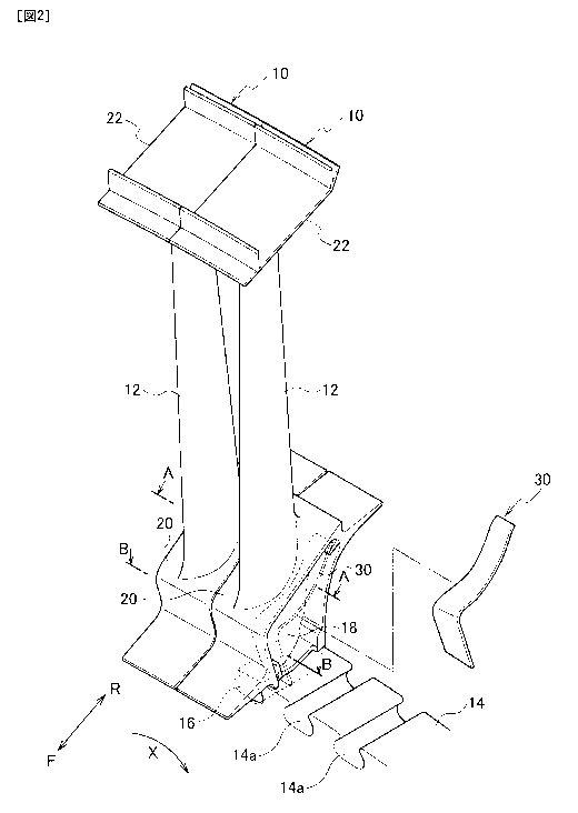
Fig. 2 is a perspective view illustrating a configuration
of a turbine rotor blade in the first embodiment of the present
invention.
6
CA 02977064 2017-08-16
[Fig. 3]
Fig. 3 is a perspective view illustrating a configuration
of a main part of the turbine rotor blade in the first embodiment
of the present invention.
[Fig. 4]
Fig. 4 is a cross-sectional view taken in the A-A direction
of Fig. 3 in the first embodiment of the present invention.
[Fig. 5]
Fig. 5 is a perspective view illustrating a configuration
of a shield member in the first embodiment of the present
invention.
[Fig. 6]
Fig. 6 is a perspective view illustrating how the shield
member is attached to the turbine rotor blade in the first
embodiment of the present invention.
[Fig. 7]
Fig. 7 is a top view illustrating how the shield member
is attached to the turbine rotor blade in the first embodiment
of the present invention.
[Fig. 8]
Fig. 8 is a cross-sectional view illustrating how the
shield member is attached to the turbine rotor blade in the first
embodiment of the present invention.
[Fig. 9]
Fig. 9 is a cross-sectional view taken in the A-A direction
of Fig. 2 in the first embodiment of the present invention.
[Fig. 10]
Fig. 10 is a cross-sectional view taken in the B-B
direction of Fig. 2 in the first embodiment of the present
invention.
7
CA 02977064 2017-08-16
[Fig. 11]
Fig. 11 is a perspective view illustrating a
configuration of a shield member in a second embodiment of the
present invention.
[Fig. 12]
Fig. 12 is a cross-sectional view illustrating how the
shield member is attached to the turbine rotor blade in the
second embodiment of the present invention.
[Fig. 13]
Fig. 13 is a cross-sectional view illustrating how the
shield member is attached between platform portions of the
adjacent turbine rotor blades in the second embodiment of the
present invention.
[Fig. 14]
Fig. 14 is a perspective view illustrating a
configuration of a shield member in a third embodiment of the
present invention.
[Fig. 15]
Fig. 15 is a cross-sectional view illustrating how the
shield member is attached to the turbine rotor blade in the third
embodiment of the present invention.
[Fig. 16]
Fig. 16 is a perspective view illustrating a
configuration of a shield member in a fourth embodiment of the
present invention.
[Fig. 17]
Fig. 17 is a cross-sectional view illustrating how the
shield member is attached to the turbine rotor blade in the
fourth embodiment of the present invention.
[Fig. 18]
8
CA 02977064 2017-08-16
Fig. 18 is a perspective view illustrating a
configuration of a shield member in a fifth embodiment of the
present invention.
[Fig. 19]
Fig. 19 is a cross-sectional view illustrating how the
shield member is attached to the turbine rotor blade in the fifth
embodiment of the present invention.
[Fig. 20]
Fig. 20 is a cross-sectional view illustrating how the
shield member is attached over gaps between platform portions
of the adjacent turbine rotor blades in the fifth embodiment
of the present invention.
[Fig. 21]
Fig. 21 is a cross-sectional view illustrating how the
shield member is attached over gaps between platform portions
of the adjacent turbine rotor blades in the fifth embodiment
of the present invention.
[Description of Embodiments]
[0018]
Using the drawings, detailed descriptions will be
hereinbelow provided for the embodiments of the present
invention.
[First Embodiment]
[0019]
Using the drawings, detailed descriptions will be
provided for a first embodiment of the present invention. To
begin with, descriptions will be provided for a turbine rotor
blade used in a jet engine such as an aircraft turbofan engine.
Fig. 1 is a diagram illustrating a configuration of an aircraft
turbofan engine 8. The aircraft turbofan engine 8 includes
9
CA 02977064 2017-08-16
turbines in plural stages, such as low-pressure turbines, for
extracting energy from a combustion gas which is obtained by
combusting a working fluid such as air. Each turbine includes
multiple turbine rotor blades arranged on the circumference of
a turbine disk.
[0020]
Fig. 2 is a perspective view illustrating a configuration
of a turbine rotor blade 10. Fig. 3 is a perspective view
illustrating a configuration of a main part of the turbine rotor
blade 10. Fig. 4 is a cross-sectional view taken in the A-A
direction of Fig. 3. Incidentally, in Fig. 2, F indicates an
upstream side of the combustion gas in a turbine axial direction,
R indicates a downstream side of the combustion gas in the
turbine axial direction, and X indicates a rotational direction
of the turbine rotor blade 10. Here, the low-pressure turbine
rotor blade is being described. However, the same descriptions
are applicable to the high-pressure turbine rotor blade.
[0021]
The turbine rotor blade 10 includes an airfoil portion
12, a dovetail portion 16 attached to a turbine disk 14, a shank
portion 18 connecting the airfoil portion 12 and the dovetail
portion 16, and a platform portion 20 provided between the
airfoil portion 12 and the shank portion 18.
[0022]
The airfoil portion 12 is formed extending in a
longitudinal direction of the turbine rotor blade 10. The
airfoil portion 12 includes a leading edge 12a located on the
upstream side of the combustion gas, and a trailing edge 12b
located on the downstream side of the combustion gas, a positive
pressure surface 12c shaped like a concave surface, and a
CA 02977064 2017-08-16
negative pressure surface 12d shaped like a convex surface. A
tip shroud 22 is provided to an upper end of the airfoil portion
12.
[0023]
The dovetail portion 16 has a function of attaching the
turbine rotor blade 10 to the turbine disk 14 by being fitted
into a disk groove 14a in the turbine disk 14. The shape of
dovetail portion 16 and the shape of the disk groove 14a are
mutually complementary to each other.
[0024]
The shank portion 18 has a function of transmitting load
from the airfoil portion 12 to the dovetail portion 16 by
connecting the airfoil portion 12 and the dovetail portion 16.
The shank portion 18 is provided to a base end side of the airfoil
portion 12 in the longitudinal direction. The shank portion
18 is formed extending from the base end side of the airfoil
portion 12 to the dovetail portion 16.
[0025]
The shank portion 18 is formed curving in accordance with
the shape of the airfoil portion 12. A side surface of the shank
portion 18 on the side of the positive pressure surface of the
airfoil portion 12 is formed in a concave shape, and the other
side surface of the shank portion 18 on the side of the negative
pressure surface of the airfoil portion 12 is formed in a convex
shape. The both sides of the shank portion 18 are each provided
with a depression-shaped pocket 24 for the purpose of weight
reduction.
[0026]
The platform portion 20 has a function of shielding the
combustion gas flowing in the turbine axial direction by being
11
CA 02977064 2017-08-16
provided between the airfoil portion 12 and the shank portion
18 in a way that the platform portion 20 is integrally connected
to the airfoil portion 12 and the shank portion 18. The platform
portion 20 includes a platform portion body 20a formed extending
in a direction intersecting the longitudinal direction of the
turbine rotor blade 10.
[0027]
The platform portion 20 includes a front skirt 20b
provided on the leading edge side of the platform portion body
20a, and provided extending in the longitudinal direction of
the turbine rotor blade 10. The platform portion 20 further
includes a rear skirt 20c provided on the trailing edge side
of the platform portion body 20a, and provided extending in the
longitudinal direction of the turbine rotor blade 10. The inner
surface of the rear skirt 20c is a convex curved surface which
is formed in a convex curved shape toward the leading edge side.
Incidentally, the inner surface of the rear skirt 20c may be
an inclining plane surface, a vertical plane surface or the like
instead of the convex curved surface.
[0028]
The inner surface of the platform portion body 20a is
provided with a platform portion body-side fitting groove 20d,
and the inner surface of the front skirt 20b is provided with
a front skirt-side fitting groove 20e. A shield member 30 to
be described later is fitted into the platform portion body-side
fitting groove 20d and the front skirt-side fitting groove 20e.
The platform portion body-side fitting groove 20d is formed
extending in a width direction intersecting a longitudinal
direction of the platform portion body 20a. The front
skirt-side fitting groove 20e is formed extending in a width
12
CA 02977064 2017-08-16
direction intersecting a longitudinal direction of the front
skirt 20b.
[0029]
Because of its exposure to high temperature due to the
combustion gas, the turbine rotor blade 10 is made from a
lightweight and high-temperature strength material such as a
ceramic matrix composite, a Ni-based superalloy, a TiAl alloy.
The turbine rotor blade 10 is manufactured by unidirectional
solidification casting, single crystal casting or the like.
[0030]
Next, the shield member will be described. Fig. 5 is a
perspective view illustrating a configuration of the shield
member 30. Fig. 6 is a perspective view illustrating how the
shield member 30 is attached to the turbine rotor blade 10. Fig.
7 is a top view illustrating how the shield member 30 is attached
to the turbine rotor blade 10. Fig. 8 is a cross-sectional view
illustrating how the shield member 30 is attached to the turbine
rotor blade 10.
[0031]
The shield member 30 is disposed over gaps between the
platform portions 20 of the adjacent turbine rotor blades 10.
The shield member 30 is made from the ceramic matrix composite.
The shield member 30 has a function of shielding the gaps between
the platform portions 20. The shield member 30 includes a
shield member body 32 and a leading edge-side shield portion
34 provided to a first end in a longitudinal direction of the
shield member body 32.
[0032]
The shield member body 32 is formed elongated and includes
a first shield surface 32a located between the shank portions
13
CA 02977064 2017-08-16
18 connected to the platform portions 20 of the adjacent turbine
rotor blades 10, and coming into contact with the inner surfaces
of the platform portion bodies 20a of the adjacent turbine rotor
blades 10 along the inner surfaces of the platform portion
bodies 20a.
[0033]
The first shield surface 32a has a function of shielding
the gaps between the platform portion bodies 20a of the adjacent
turbine rotor blades 10 by touching the inner surfaces of the
platform portion bodies 20a of the adjacent turbine rotor blades
along the inner surfaces of the platform portion bodies 20a
due to centrifugal force acting on the first shield surface 32a
while the turbine rotor blades 10 are rotating. The first
shield surface 32a is shaped substantially like a plane surface,
corresponding to the inner surfaces of the platform portion
bodies 20a of the adjacent turbine rotor blades 10.
[0034]
The shield member body 32 is formed extending in the
longitudinal direction of the shield member body 32, but curved
in a plane in order to correspond to the shapes of the shank
portions 18 of the adjacent turbine rotor blades 10. More
specifically, one side edge 32b of the shield member body 32
in a width direction intersecting the longitudinal direction
of the shield member body 32 is formed in a convex curved shape,
while the other side edge 32c of the shield member body 32 in
the width direction intersecting the longitudinal direction of
the shield member body 32 is formed in a concave curved shape.
[0035]
In the case where the shield member 30 is attached to the
adjacent turbine rotor blades 10, the convex side edge 32b of
14
CA 02977064 2017-08-16
the shield member body 32 corresponds to the concave side
surface of the shank portion 18, while the concave side edge
32c of the shield member body 32 corresponds to the convex side
surface of the other shank portion 18. This inhibits
interference between the shield member body 32 and the shank
portions 18 even in a case where the side surfaces of the shank
portions 18 are formed curving in accordance with the shapes
of the blade portions 12. Thus, the shield performance of the
shield member 30 can be enhanced.
[0036]
The shield member body 32 includes a shield member
body-side fitting portion 32d provided to a second end in
longitudinal-direction of the shield member body 32. The
shield member body-side fitting portion 32d is fitted into the
platform portion body-side fitting groove 20d. The shield
member body 32 can be easily positioned by fitting the shield
member body-side fitting portion 32d into the platform portion
body-side fitting groove 20d.
[0037]
The longitudinal-direction length of the shield member
body 32 is set substantially equal to the length of the platform
portion body 20a from its leading edge side to its trailing edge
side, and is set within a range of 50 mm to 60 mm, for example.
[0038]
The width of the shield member body 32 is set larger than
the gap between the platform portion bodies 20a of the adjacent
turbine rotor blades 10, but smaller than the space between the
shank portions 18 of the adjacent turbine rotor blades 10. The
width of the shield member body 32 at any point in the
longitudinal direction of the shield member body 32 may be set
CA 02977064 2017-08-16
equal to, or different from each other. The width of the shield
member body 32 is set within a range of 20 mm to 30 mm, for
example.
[0039]
The thickness of the shield member body 32 is set at a
thickness which enables the shield member body 32 to secure
rigidity needed to retain its shape. The thickness of the
shield member body 32 is set within a range of 1 mm to 2 mm,
for example.
[0040]
The leading edge-side shield portion 34 is formed
elongated. A first end in a longitudinal direction of the
leading edge-side shield portion 34 is integrally provided to
the first end in the longitudinal direction of the shield member
body 32 such that the leading edge-side shield portion 34 is
bent from the shield member body 32. The leading edge-side
shield portion 34 includes a second shield surface 34a. The
second shield surface 34a is located between the shank portions
18 of the adjacent turbine rotor blades 10, and contacts with
the inner surfaces of the front skirts 20b of the adjacent
turbine rotor blades 10 along the inner surfaces of the front
skirts 20b.
[0041]
The second shield surface 34a has a function of shielding
the gap between the front skirts 20b of the adjacent turbine
rotor blades 10 by contacting with the inner surfaces of the
front skirts 20b of the adjacent turbine rotor blades 10 along
the inner surfaces of the front skirts 20b due to centrifugal
force acting on the second shield surface 34a while the turbine
rotor blades 10 are rotating. The second shield surface 34a
16
CA 02977064 2017-08-16
is shaped like a plane surface, a curving surface or the like,
corresponding to the inner surfaces of the front skirts 20b of
the adjacent turbine rotor blades 10.
[0042]
One side edge 34b and the other side edge 34c of the leading
edge-side shield portion 34 in a width direction intersecting
the longitudinal direction of the leading edge-side shield
portion 34 may be formed substantially in a straight line, or
may be formed curving.
[0043]
The leading edge-side shield portion 34 includes a
leading edge-side shield portion-side fitting portion 34d
provided to a second end in longitudinal direction of the
leading edge-side shield portion 34. The leading edge-side
shield portion-side fitting portion 34d is fitted into the front
skirt-side fitting groove 20e. The leading edge-side shield
portion 34 can be easily positioned by fitting the leading
edge-side shield portion-side fitting portion 34d into the
front skirt-side fitting groove 20e.
[0044]
The longitudinal-direction length of the leading
edge-side shield portion 34 is set substantially equal to the
length of the front skirt 20b from the airfoil portion 12-side
to the dovetail portion 16-side. The longitudinal-direction
length of the leading edge-side shield portion 34 is set within
a range of 20 mm to 30 mm, for example.
[0045]
The width of the leading edge-side shield portion 34 is
set larger than the gap between the front skirts 20b of the
adjacent turbine rotor blades 10, but smaller than the space
17
CA 02977064 2017-08-16
between the shank portions 18 of the adjacent turbine rotor
blades 10. The width of the leading edge-side shield portion
34 at any point in the longitudinal direction of the leading
edge-side shield portion 34 may be set equal to, or different
from each other. The width of the leading edge-side shield
portion 34 is set within a range of 20 mm to 30 mm, for example.
[0046]
The thickness of the leading edge-side shield portion 34
is set at a thickness which enables the leading edge-side shield
portion 34 to secure rigidity needed to retain its shape. The
thickness of the leading edge-side shield portion 34 is set
within a range of 1 mm to 2 mm, for example. Incidentally, the
thickness of the leading edge-side shield portion 34 may be set
equal to that of the shield member body 32.
[0047]
The shield member 30 is made from the ceramic matrix
composite. The ceramic matrix composite is a ceramic
fiber-reinforced ceramic composite material obtained by
reinforcing a ceramic matrix with ceramic fibers. For example,
a SiC/SiC composite material obtained by reinforcing a SiC
matrix with SiC fibers, a S1C/A1203 composite material obtained
by reinforcing a SiC matrix with A1203 fibers, or the like may
be used as the ceramic matrix composite. The ceramic matrix
composite is excellent in heat resistance and oxidation
resistance. For this reason, although the shield member 30 is
exposed to the combustion gas, it is possible to inhibit damage
on the shield member 30, such as deformation, oxidation and the
like caused by the heat exposure. In addition, the ceramic
matrix composite is more lightweight than heat resistant alloys
(such as a Ni-based superalloy and a TiAl alloy) . For this
18
CA 02977064 2017-08-16
reason, it is possible to reduce the weight of the aircraft
turbofan engine 8 and the like. Moreover, the ceramic matrix
composite is good in toughness and the like as a result of the
ceramic fiber reinforcement. For this reason, even in a case
where the shield member 30 is impacted by the rotations of the
turbine rotor blades 10, and the like, fracture of the shield
member 30 can be inhibited.
[0048]
Next, a method of manufacturing the shield member 30 will
be described. To begin with, a preform corresponding to the
shape of the shield member 30 is formed by trimming, stitching,
etc. a two-dimensional or three-dimensional fabric made from
ceramic fibers. SiC fibers, A1203 fibers, and the like may be
used as the ceramic fibers. The preform is placed inside a mold.
A polymer material for the matrix is filled into the mold.
Thereby, the preform is impregnated with the polymer material.
The preform impregnated with the polymer material is heated and
fired to form a ceramic matrix of SiC or the like. Incidentally,
chemical vapor infiltration, solid phase infiltration and the
like may be used for the matrix forming. The chemical vapor
infiltration makes it possible to form a ceramic matrix of SiC
or the like by a thermal decomposition reaction and the like
of a material gas. The solid phase infiltration makes it
possible to form a ceramic matrix of SiC or the like by
impregnating the preform with a mixed powder of Si and C, for
example, making Si and C react on each other in the preform.
In this manner, the shield member 30 can be made from the ceramic
matrix composite.
[0049]
Next, how the shield member 30 works will be described.
19
CA 02977064 2017-08-16
Fig. 9 is a cross-sectional view taken in the A-A direction of
Fig. 2. Fig. 10 is a cross-sectional view taken in the B-B
direction of Fig. 2.
[0050]
First of all, the shield member 30 is attached over the
gaps 36, 38 between the platform portions 20 of the adjacent
turbine rotor blades 10. More specifically, the shield member
30 is attached by being positioned by fitting the shield member
body-side fitting portion 32d into the platform portion
body-side fitting groove 20d, and fitting the leading edge-side
shield portion-side fitting portion 34d into the front
skirt-side fitting groove 20e. Thereby, the shield member 30
is disposed facing the gaps 36, 38 between the platform portions
20 of the adjacent turbine rotor blades 10.
[0051]
While receiving a combustion gas flow flowing in the
turbine axial direction, the turbine rotor blades 10 makes
rotary motion integrally with the turbine disk 14. This rotary
motion makes the centrifugal force act on the turbine rotor
blades 10. This centrifugal force makes the shield member 30,
disposed over the gaps 36, 38 between the platform portions 20
of the adjacent turbine rotor blades 10, touch and come into
close contact with the inner surfaces of the platform portions
20. Thus, the gaps 36, 38 between the platform portions 20 are
shielded with the shield member 30.
[0052]
More specifically, the gap 36 between the platform
portion bodies 20a of the adjacent turbine rotor blades 10 is
shielded with the first shield surface 32a of the shield member
body 32 since the first shield surface 32a touches and comes
CA 02977064 2017-08-16
into close contact with the inner surfaces of the platform
portion bodies 20a along the inner surfaces of the platform
portion bodies 20a.
[0053]
Meanwhile, the gap 38 between the front skirts 20b of the
adjacent turbine rotor blades 10 is shielded with the second
shield surface 34a of the leading edge-side shield portion 34
since the second shield surface 34a touches and comes into close
contact with the inner surfaces of the front skirts 20b along
the inner surfaces of the front skirts 20b.
[0054]
Thus, the combustion gas is inhibited from flowing into
the inside of the platform portions 20 through the gap 36 between
the platform portion bodies 20a and the gap 38 between the front
skirts 20b. This makes it possible to inhibit the exposure of
the turbine disk 14 to the heat of the combustion gas.
[0055]
The foregoing configuration makes it possible to dispose
the shield member, made from the ceramic matrix composite, over
the gaps between the platform portions of the adjacent turbine
rotor blades. Thereby, the combustion gas can be inhibited from
flowing into the inside of the platform portions through the
gaps between the platform portions of the adjacent turbine rotor
blades. Thus, the heat exposure of the turbine disk can be
inhibited. In addition, since the shield member is made from
the ceramic matrix composite, damage on the shield member due
to the heat exposure can be inhibited although the shield member
is exposed to the combustion gas.
[0056]
According to the foregoing configuration, even in the
21
CA 02977064 2017-08-16
case where the shank portion is formed curving in accordance
with the shape of the airfoil portion, the shield member body
is formed curved in a plane in accordance with the side surface
of the shank portion. This inhibits the interference between
the shield member body and the shank portion. Thus, the shield
performance of the shield member can be enhanced.
[0057]
The foregoing configuration makes it possible to easily
attach the shield member over the gaps between the platform
portions of the adjacent turbine rotor blades by fitting the
shield member body-side fitting portion into the platform
portion body-side fitting groove and fitting the leading
edge-side shield portion-side fitting portion into the front
skirt-side fitting groove. The foregoing configuration
further makes it possible to easily and accurately position and
dispose the shield member.
[0058]
[Second Embodiment]
Next, using the drawings, detailed descriptions will be
provided for a second embodiment of the present invention. Fig.
11 is a perspective view illustrating a configuration of a
shield member 40 of the second embodiment. Fig. 12 is a
cross-sectional view illustrating how the shield member 40 of
the second embodiment is attached to the turbine rotor blade
10. Fig. 13 is a cross-sectional view illustrating how the
shield member 40 of the second embodiment is attached over a
gap between the platform portions 20 of the adjacent turbine
rotor blades 10. Incidentally,
Fig. 13 is the diagram
corresponding to Fig. 9 concerning the first embodiment, and
is the cross-sectional view taken in the A-A direction of Fig.
22
CA 02977064 2017-08-16
2 in the case where the shield member 40 of the second embodiment
is attached there instead of the shield member 30 of the first
embodiment. In addition, the same elements are denoted by the
same reference signs, and detailed descriptions for such
elements are omitted.
[0059]
The shield member 40 of the second embodiment is different
from the shield member 30 of the first embodiment in that the
shield member 40 includes restriction portions 42. The
restriction portions 42 are provided at parts of both sides 32b,
32c in the longitudinal direction of the shield member body 32.
The restriction portions 42 are formed projecting in the width
direction intersecting the longitudinal direction of the shield
member body 32, and restrict the movement of the shield member
40 in the width direction by coming into contact with the
corresponding side surfaces of the shank portions 18 of the
adjacent turbine rotor blades 10.
[0060]
When the shield member 40 is attached over the gaps between
the platform portions 20 of the adjacent turbine rotor blades
10, the restriction portions 42 have a function of restricting
the movement of the shield member 40 in the width direction by
coming into surface contact or line contact with the
corresponding side surfaces of the shank portions 18 of the
adjacent turbine rotor blades 10, and thereby holding the shield
member 40. This restricts the movement of the shield member
40 in the width direction, and accordingly inhibits the shield
member 40 from coming off the turbine rotor blades 10 in an
initial stage of the rotary motion of the turbine rotor blades
and the like. This further enhances the accuracy of
23
CA 02977064 2017-08-16
positioning the shield member 40.
[0061]
The restriction portions 42 are formed projecting in the
width direction intersecting the longitudinal direction of the
shield member body 32, and curving toward the back surface of
the first shield surface 32a. The restriction portions 42 may
be shaped like a rectangle, a triangle, a circle and the like.
[0062]
The side edges 32b, 32c may be provided with the respective
restriction portions 42 at the same position, or at different
positions, in the longitudinal direction of the shield member
body 32. The both side edges 32b, 32c may be each provided with
one restriction portion 42, or with multiple restriction
portions 42. Furthermore, the number of restriction portions
42 provided to the one side edge 32b and the number of restriction
portions 42 provided to the other side edge 32c may be different
from each other. The side edges 32b, 32c may be provided with
the restriction portions 42 at their center portions in the
longitudinal direction of the shield member body 32,
respectively. Otherwise, the side edges 32b, 32c may be
provided with the restriction portions 42 at the first end-side
positions, or the second end-side positions, in the
longitudinal direction of the shield member body 32,
respectively.
[0063]
In the case where the shielding member 40 is made from
the ceramic matrix composite, at first, a preform corresponding
to the shape of the shield member 40 is formed by trimming,
stitching, etc. a two-dimensional or three-dimensional fabric
made from ceramic fibers. The preform is placed inside a mold.
24
CA 02977064 2017-08-16
Its portions corresponding to the restriction portions 42 are
curved and set in the mold to be molded into the restriction
portions 42. The ceramic matrix is formed in the same way as
that for the shield member 30 of the first embodiment is. For
this reason, detailed descriptions will be omitted.
[0064]
The foregoing configuration can bring about the same
effects as the shield member of the first embodiment does.
Furthermore, when the shield member is attached over the gaps
between the platform portions of the adjacent turbine rotor
blades, the foregoing configuration makes the restriction
portions of the shield member body come into contact with the
corresponding side surfaces of the shank portions of the
adjacent turbine rotor blades to hold the shield member. The
foregoing configuration thereby restricts the movement of the
shield member in the width direction, and thus inhibits the
shield member from coming off. Moreover, the foregoing
configuration enhances the accuracy of positioning the shield
member.
[0065]
[Third Embodiment]
Next, using the drawings, detailed descriptions will be
provided for a third embodiment of the present invention. Fig.
14 is a perspective view illustrating a configuration of a
shield member 50 of the third embodiment. Fig. 15 is a
cross-sectional view illustrating how the shield member 50 of
the third embodiment is attached to the turbine rotor blade 10.
Incidentally, the same elements are denoted by the same
reference signs, and detailed descriptions for such elements
are omitted.
CA 02977064 2017-08-16
[0066]
The rear skirt 20c of the platform portion 20 includes
a holding portion 20f, provided to the inner surface of the rear
skirt 20c, for holding the second end in the longitudinal
direction of the shield member body 32 of the shield member 50
of the third embodiment. The holding portion 20f is formed from
a holding surface which is made from a part of the inner surface
of the rear skirt 20c, and which is a convex curved surface
projecting toward the leading edge side. The shield member 50
of the third embodiment is different from the shield member 30
of the first embodiment in that the shield member SO includes
a curving portion 52 provided to the second end in the
longitudinal direction of the shield member body 32, formed
curving toward the back surface of the first shield surface 32a,
and configured to come into contact with the holding portions
20f of the rear skirts 20c of the adjacent turbine rotor blades
10.
[0067]
When the shield member 50 is attached over the gaps between
the platform portions 20 of the adjacent turbine rotor blades
10, the curving portion 52 provided to the second end of the
shield member body 32 comes into surface contact or line contact
with the holding surface which is the holding portion 20f of
the rear skirt 20c, and thereby holds the shield member body
32. Therefore the platform portion body-side fitting groove
20d provided to the platform portion body 20a for holding the
shield member body 32 is made unnecessary. This simplifies the
configuration of the platform portion 20, and accordingly makes
it possible to easily manufacture the turbine rotor blade 10.
Incidentally, the holding surface of the holding portion 20f
26
CA 02977064 2017-08-16
is not limited to the convex curved surface, and may be an
inclining plane surface. Otherwise, the holding portion 20f
may be formed by providing a protrusion to the inner surface
of the rear skirt.
[0068]
In the case where the shield member 50 is made from the
ceramic matrix composite, at first, a preform corresponding to
the shape of the shield member 50 is formed by trimming,
stitching, etc. a two-dimensional or three-dimensional fabric
made from ceramic fibers. The preform is placed inside a mold.
Its portion corresponding to the curving portion 52 is curved
and set in the mold to be molded into the curving portion 52.
The ceramic matrix is formed in the same way as that for the
shield member 30 of the first embodiment is. For this reason,
detailed descriptions will be omitted.
[0069]
The foregoing configuration can bring about the same
effects as the shield member of the first embodiment does.
Furthermore, the platform portion body-side fitting groove
provided to the platform portion body for holding the shield
member body is made unnecessary. The foregoing configuration
thus simplifies the configuration of the platform portion, and
accordingly makes it possible to easily manufacture the turbine
rotor blade.
[0070]
[Fourth Embodiment]
Next, using the drawings, detailed descriptions will be
provided for a fourth embodiment of the present invention. Fig.
16 is a perspective view illustrating a configuration of a
shield member 60 of the fourth embodiment. Fig. 17 is a
27
CA 02977064 2017-08-16
cross-sectional view illustrating how the shield member 60 of
the fourth embodiment is attached to the turbine rotor blade
10. Incidentally, the same elements are denoted by the same
reference signs, and detailed descriptions for such elements
are omitted.
[0071]
The rear skirt 20c of the platform portion 20 includes
a holding portion 20f, provided to the inner surface of the rear
skirt 20c, for holding the second end in the longitudinal
direction of the shield member body 32 of the shield member 60
of the fourth embodiment. The shield member 60 of the fourth
embodiment is different from the shield member 30 of the first
embodiment in that the shield member 60 includes the restriction
portions 42 of the shield member 40 of the second embodiment,
and the curving portion 52 of the shield member 50 of the third
embodiment.
[0072]
In the case where the shielding member 60 is made from
the ceramic matrix composite, at first, a preform corresponding
to the shape of the shield member 60 is formed by trimming,
stitching, etc. a two-dimensional or three-dimensional fabric
made from ceramic fibers. The preform is placed inside a mold.
Its portions corresponding to the restriction portions 42 and
the curving portion 52 are curved and set in the mold to be molded
into the restriction portions 42 and the curving portion 52.
The ceramic matrix is formed in the same way as that for the
shield member 30 of the first embodiment is. For this reason,
detailed descriptions will be omitted.
[0073]
The foregoing configuration not only can bring about the
28
CA 02977064 2017-08-16
same effects as the shield member of the first embodiment does,
but also can bring about the same effects as the shield member
of the second embodiment does, and the same effects as the shield
member of the third embodiment does.
[0074]
[Fifth Embodiment]
Next, using the drawings, detailed descriptions will be
provided for a fifth embodiment of the present invention. Fig.
18 is a perspective view illustrating a configuration of a
shield member 70 of the fifth embodiment. Fig. 19 is a
cross-sectional view illustrating how the shield member 70 of
the fifth embodiment is attached to the turbine rotor blade 10.
Fig. 20 is a cross-sectional view illustrating how the shield
member 70 of the fifth embodiment is attached over a gap between
the platform portions 20 of the adjacent turbine rotor blades
10. Fig. 21 is a cross-sectional view illustrating how the
shield member 70 of the fifth embodiment is attached over a gap
between the platform portions 20 of the adjacent turbine rotor
blades 10. Incidentally, Fig. 20 is the diagram corresponding
to Fig. 9 concerning the first embodiment, and is the
cross-sectional view taken in the A-A direction of Fig. 2 in
the case where the shield member 70 of the fifth embodiment is
attached there instead of the shield member 30 of the first
embodiment. Fig. 21 is the diagram corresponding to Fig. 10
concerning the first embodiment, and is the cross-sectional
view taken in the B-B direction of Fig. 2 in the case where the
shield member 70 of the fifth embodiment is attached there
instead of the shield member 30 of the first embodiment. In
addition, the same elements are denoted by the same reference
signs, and detailed descriptions for such elements are omitted.
29
CA 02977064 2017-08-16
[0075]
The rear skirt 20c of the platform portion 20 includes
a holding portion 20f, provided to the inner surface of the rear
skirt 20c, for holding the second end in the longitudinal
direction of the shield member body 32 of the shield member 70
of the fifth embodiment. The shield member 70 of the fifth
embodiment includes first contact portions 72 provided to full
lengths of both sides in the longitudinal direction of the
shield member body 32. The first contact portions 72 are formed
projecting in the width direction intersecting the longitudinal
direction of the shield member body 32, and curving toward the
back surface of the first shield surface 32a. The first contact
portions 72 come into contact with the corresponding side
surfaces of the shank portions 18 of the adjacent turbine rotor
blades 10, and with the holding portion 20f of the rear skirt
20c. The shield member 70 further includes second contact
portions 74 provided to full lengths of both sides in in the
longitudinal direction of the leading edge-side shield portion
34. The second contact portions 74 are formed projecting in
the width direction intersecting the longitudinal direction of
the leading edge-side shield portion 34, and curving toward the
back surface of the second shield surface 34a. The second
contact portions 74 come into contact with the corresponding
side surfaces of the shank portions 18 of the adjacent turbine
rotor blades 10. As described above, the shield member 70 of
the fifth embodiment is different from the shield member 30 of
the first embodiment in that the shield member 70 includes the
first contact portions 72 and the second contact portions 74.
[0076]
When the shield member 70 is disposed facing the gaps 36,
CA 02977064 2017-08-16
38 between the platform portions 20 of the adjacent turbine
rotor blades 10 by being attached over the gaps 36, 38, the first
contact portions 72 provided to the shield member body 32 come
into surface contact or line contact with the corresponding side
surfaces of the shank portions 18 of the adjacent turbine rotor
blades 10, and the second contact portions 74 provided to the
leading edge-side shield portion 34 come into surface contact
or line contact with the corresponding side surfaces of the
shank portions 18 of the adjacent turbine rotor blades 10. The
foregoing configuration thereby makes the first contact
portions 72 and the second contact portions 74 hold the shield
member 70. This restricts the movement of the shield member
70 in the width direction, and accordingly inhibits the shield
member 70 from coming off the turbine rotor blades 10 in an
initial stage of the rotary motion of the turbine rotor blades
and the like. This further enhances the accuracy of
positioning the shield member 70.
[0077]
Furthermore, when the shield member 70 is disposed facing
the gaps 36, 38 between the platform portions 20 of the adjacent
turbine rotor blades 10 by being attached over the gaps 36, 38,
the rear parts of the first contact portions 72 provided to the
shield member body 32 come into contact with the holding
portions 20f of the rear skirts 20c, and thereby holds the shield
member body 32. Therefore the platform portion body-side
fitting groove 20d provided to the platform portion body 20a
for holding the shield member main body 32 is made unnecessary.
This simplifies the configuration of the platform portion 20,
and accordingly makes it possible to easily manufacture the
turbine rotor blade 10.
31
CA 02977064 2017-08-16
[0078]
Moreover, the shield member 70 is provided, at the second
end of the leading edge-side shield portion 34 on the side of
the dovetail portion 16, with a projectingly-formed leading
edge-side shield portion-side fitting portion 76 configured to
be fitted into the front skirt-side fitting groove 20e provided
in the inner surface of the front skirt 20b.
[0079]
In the case where the shield member 70 is made from the
ceramic matrix composite, at first, a preform corresponding to
the shape of the shield member 70 is formed by trimming,
stitching, etc. a two-dimensional or three-dimensional fabric
made from ceramic fibers. The preform is placed inside a mold.
Its portions corresponding to the first contact portions 72 and
the second contact portions 74 are curved and set in the mold
to be molded into the first contact portions 72 and the second
contact portions 74. The ceramic matrix is formed in the same
way as that for the shield member 30 of the first embodiment
is. For this reason, detailed descriptions will be omitted.
[0080]
The foregoing configuration can bring about the same
effects as the shield member of the first embodiment does.
Furthermore, when the shield member is attached over the gaps
between the platform portions of the adjacent turbine rotor
blades, the foregoing configuration makes the first contact
portions, provided to the shield member body, come into contact
with the corresponding side surfaces of the shank portions of
the adjacent turbine rotor blades, and makes the second contact
portions, provided to the leading edge-side shield portion,
come into contact with the corresponding side surfaces of the
32
CA 02977064 2017-08-16
shank portions of the adjacent turbine rotor blades. The
foregoing configuration thereby makes the first contact
portions and the second contact portions hold the shield member.
This restricts the movement of the shield member in the width
direction, and accordingly inhibits the shield member from
coming off the turbine rotor blades. This further enhances the
accuracy of positioning the shield member.
[0081]
Furthermore, when the shield member is attached over the
gaps between the platform portions of the adjacent turbine rotor
blades, the foregoing configuration makes the first contact
portions, provided to the shield member body, come into contact
with the holding portions of the rear skirts, and thus hold the
shield member body. Therefore the platform portion body-side
fitting groove provided to the platform portion body is made
unnecessary, and accordingly this makes it possible to easily
manufacture the turbine rotor blade.
[Industrial Applicability]
[0082]
The present invention is useful for a jet engine such as
an aircraft turbofan engine, since the present invention makes
it possible to shield the gaps between the platform portions
of the adjacent turbine rotor blades.
33