Note: Descriptions are shown in the official language in which they were submitted.
CA 02977547 2017-08-23
WO 2016/134405 PCT/AU2016/000055
DENTAL IMPLANT IDENTIFICATION SYSTEM
TECHNICAL. FIELD
The present invention relates to dental implants and, in particular, to
devices, systems
and methods. which allow radio frequency identification of dental implants.
More
particularly, the present invention relates to radio frequency identification
systems of
both the non-contact type and of the contact type which can be used for
identifying
dental implants.
BACKGROUND ART
Dental implants are root replacement devices used in dentistty to. provide a
support for
prosthetic teeth or other dental appliances. They are serewed into a suitably
prepared
site in the jaw bone with the screw serving as a fixture onto which a
prosthetic tooth or
other dental. appliance may be mounted. Dental implants have been in use .for
over 40
years and have been extremely successful in treating patients with tooth loss.
The
efficacy and success of dental implants and the rising demand for cosmetic
dentistry
worldwide across all age groups has led to an exponential growth in the.
industry and to
a very large number of different types or brands of dental implants that have
been made
available.
This growth has resulted in a vast array of design variations in dental
implants with
incompatibility existing between dental implants from different manufacturers.
In
general, the industry is Characterized by a lack. of standardization in the
devices and
systems that are used at the clinical level, and this. incompatibility at the
prosthetic
interface is compounded by the large range of possible dental implants. This
poses an
extreme challenge for the clinician when faced with re-servicing existing
dental
implants, such. as is required when replacing a broken prosthetic tooth.
Frequently, the
availability of proper dental records is lading, especially when patients move
locations,
CA 02977547 2017-08-23
WO 2016/134405 PCT/AU2016/000055
2
and so it may be impossible in those circumstances to reliably identify the
nature of the
existing dental implant in need of re-servicing.
The current method of identification relies largely on radiographic imaging.
However,
identification of the brand of a dental implant screwed in the jaw bone using
radiographic images of brand specific features is difficult and unreliable and
requires
the clinician to stay abreast of a in),riad of dental implant systems that are
regularly
changing.
Radio frequency identification (RF1D) systems are well known in some other
industries
for their usefulness in quickly and reliably identifying. small objects. RFID
systems
conventionally include an RFID tag which may be programmed and interrogated by
a
reader device. The RPM tag has an integrated circuit with a radio transceiver
and
antenna. The integrated circuit may be programmed by the reader device to
contain
identification and other application specific information:RPM systems compared
to
other identification means, such as physical identifiers, offer the
significant advantage
of storing a large amount of digital information in a physically small form.
US Patent Application Publication No. 2009/0155744 Al (by Jandali) discloses a
.20 dental implant identification system based. on the concept of using
radio frequency
identification (RF1D) devices within dental. implant screws as a means of
identification.
Other than disclosing that an RF1D tag is positioned at the bottom of an
internal bore
within the dental implant screw, no information is provided in landali as to
the
necessary technical details of the RFED tag and its antenna. in particular,
there is no
disclosure of the structure (or configuration) and orientation of the RFD tag
and its
antenna. within the screw.
Currently, there are no known. dental implants that are being manufactured
with RF1D
tags. The common structure of RF1D tags in the time leading up to Jandali
consisted of
a tag mounted on a. carrier substrate with the antenna printed on a carrier
Ward. This is
inexpensive to construct and the flat planar configuration is suitable for
many
CA 02977547 2017-08-23
WO 2016/134405 PCT/AU2016/000055
3
applications. However,. the magnetic field coupling, from a reader antenna to
the tag
antenna and the resulting received, voltage supplying the tag will be
extremely weak
owing to the small flat planar configuration of the tag antenna. The received
voltage (or
received signal strength) will be too weak to power up the circuitry within
the tag which
requires a minimum of 1 volt in most tags. Furthermore, tag antennae having a
flat
planar configuration present difficulties in the manner in which they may be
located
within a: confined space, such as within the cylindrical bore of a dental
implant screw.
The use of RFID tags when placed in a very small, completely enclosed, metal
cavity is
extremely challenging. Placing an MD tag within a very small space at the
bottom of a
cavitywithin a dental implant screw with a. volume typically of <5 mm3 poses
severe
performance limitations. These performance limitations arise from the small
size of the
antenna and the effect of the surrounding metal on the performance of the
radio
transceiver and antenna.
Dental implants are typically constructed of titanium or zirconium and
associated alloys
since these materials provide the necessary strength and biocompatibility
requirements
for prolonged and effective use. These materials, and any other material of
similar
conductivity and thickness, provide a shield that significantly attenuates the
radio
.20 frequency signal.. The amount of attenuation is an exponential function
of the skin
depth of the material(s) used to construct the dental implant.
Further deterioration of the received signal strength occurs due to the close
proximity of
the metal to the. tag antenna which decreases the resonant signal by degrading
the
antenna's electrical properties. The often deleterious effect of materials
(especially
conductive materials) in close proximity to antennas is well. known. Due to
these
extremely challenging conditions, RED devices have not yet been used for the
putpose
of identification of dental: implants.
The present inventors have recognised that. REID systems- offer the potential
to address
all the problems associated with current methods of identifying dental
implants and
CA 02977547 2017-08-23
WO 2016/134405 PCT/AU2016/000055
4
have also recognised that the vast information storage capability of RFID
systems may
be used for patient. dental record and other user information as desired by
the clinician.
The present inventors have also recognised. that. any REED systems to be used
for
identifying dental implants can be either of non-contact type or of the
contact type.
However, the present inventors have equally recognised that for .RFID systems
to
perform at a sufficiently high level when. used for identifying dental
implants by way of
RFD tags positioned therewithin and for storing information, significant
changes to the
configuration (i.e. structure and/or orientation) of at least the REID tag are
needed.
It is a first discovery of the present inventors that, for a non-contact type
of RFID
system useful .for identifying dental implants, a coil structure of the RFID
tag antenna
positioned within a dental implant is more advantageous than a flat planar
structure,
and that such an RFID tag antenna coil must be orientated in a particular
manner within
a dental implant to optimize the magnetic field coupling from a reader antenna
to the
tag antenna and hence optimise the received signal strength needed to power up
the
circuitry within the tag.
it has been found by the present inventors that such a non-contact type of
RFID system
useful for identifying dental implants may utilize a reader antenna that can
either be
positioned -outside the dental implant or inside a tau containing cavity of
the dental
implant.
It is a second discovery of the present inventors that, for a contact type of
RFID system
useful for identifying dental implants, an RFD tag in the form of an
integrated circuit
(IC) between two contact electrodes and positioned inside a cavity of a dental
implant
can be .used, and that such an RFID tag circuit may be activated.by contact
with a tip of
a reader contact probe inserted within the cavity of the dentalim.plant.
CA 02977547 2017-08-23
WO 2016/134405 PCT/AU2016/000055
It has been found by the present inventors that, by putting these discoveries
into
practical implementation in an 'REID system for identifying dental implants,
the
aforementioned problems and shortcomings of the prior art can be overcome or
at least
substantially ameliorated.
5
SUMMARY OF INVENTION
According to one aspect ofa first form of the present invention, there is
provided a
dental implant identification system of the non-contact type, comprising:
(a) a dental implant having a radio frequency identification tag which stores
information, for identification of the dental implant, the tag including a tag
antenna coil
having a first coil axis,
(b) a reader device for activating the tag and for reading the information
stored on the
tag when the information is transmitted from the tag upon activation thereof,
the reader
device including a reader antenna coil having a second coil axis, and
(c) information processing means for processing the identification information
read. by
the reader device,
wherein the radio frequency identification tag is so cupful:tired within the
dental
implant to provide an optimal reading of the identification: information when
the reader
.20 antenna coil is positioned alongside the tag antenna coil, and the
second coil axis is
substantially aligned with the first coil axis, and when the reader device
activates the
tag.
Preferably, the radio frequency identification tag is located inside a.cavity
within a main
body of the dental implant.
In.one preferred arrangement, the reader device is configured such that the
reader
antenna coil, when positioned alongside the tag antenna coil and when the
first coil axis
and the second coil axis are substantially aligned, is outside the main body
of the dental
implant.
CA 02977547 2017-08-23
WO 2016/134405 PCT/AU2016/000055
6
hi another preferred arrangement, the reader device is configured such that
the reader
antenna coil., when positioned alongside the tag antenna. coil and when the
first soil axis
and the second coil axis are substantially aligned, is inside the cavity of
the main body
of the dental implant.
Preferably, the information processing means is a computer associated with the
reader
device for accessing a database containing information relating to the
identification
information.
It is preferred. that the radio frequency identification tag further includes
an information
storage element and an integrated control circuit electrically connected.
between the tag
antenna coil and the storage element and operable to activate the storage
element in
response to a voltage being generated in the tag antenna coil when the tag
antenna coil
and the reader antenna coil are magnetic. field coupled.
In a preferred form, the identification infonnation is stored on a microchip.
The tag antenna coil preferably operates as a passive power supply for the
tag.
.20 In one preferred embodiment, the reader device has a single reader
antenna coil.
In another preferred embodiment; the reader device has two reader antenna
coils.
According to another aspect of the first form of the present invention, there
is provided
a dental implant for engagement to a jaw bone, the dental implant comprising a
main
body having a longitudinal axis and an outer threaded surface for screwing the
main
body into the jaw bone in the direction of the longitudinal axis, the main
body having
an abutment for connecting a prosthetic tooth thereto, a cavity within the
main body, a
radio frequency identification tag positioned within the cavity for storing
information
for identification of the implant, the tag including an integrated circuit and
a tag antenna
coil, having a tag coil axis that is orientated perpendicularly to the.
longitudinal axis of
CA 02977547 2017-08-23
WO 2016/134405 PCT/AU2016/000055
7
the main body; whereby the tag antenna coil of the radio frequency
identification tag is
able to be magnetic field coupled with a reader antenna coil of a reader
device when the
reader antenna coil is positioned alongside the. tag antenna coil and when a
reader coil
axis of the reader antenna. coil is orientated substantially perpendicularly
to the
longitudinal axis of the. main body, the magnetic field coupling resulting in
a voltage
being generated in the tag antenna coil that is of a signal strength
sufficient to cause the
integrated circuitwithin the tag tobe powered up so that the information can
be read by
the reader device:
According to one aspect of a second form of the present invention, there is
provided a
dental implant identification system of the contact type, comprising:
(a) a dental implant having a main body, a cavity within the main body, and a
radio
frequency identification tag located inside the cavity, the radio frequency
identification
tag storing information for identification of the dental implant and including
an
integrated circuit between two contact electrodes,
(b) a reader device for activating the tag and for reading the information
stored on the
tag When the information is transmitted from the tag upon activation thereof,
the reader
device including a reader contact terminal, and
(c) information processing means for processing the identification information
read by
.20 the reader device,
wherein the radio frequency identification tag is so configured within the
dental.
implant to provide an optimal reading of the identification information when
the reader
contact terminal is inserted into the cavity and.contacted against one of the
contact
electrodes, and when the reader device activates the tag.
Preferably, the information processing means is a computer associated with the
reader
device for accessing a database containing information relating to the
identification
information.
In a preferred, form, the identification information is stored on a microchip.
CA 02977547 2017-08-23
WO 2016/134405 PCT/AU2016/000055
8
According to another aspect of the second form of the present invention, there
is
provided, a dental implant for engagement to a jaw bone, the dental implant
comprising
a main body having 4 longitudinal axis and an outer threaded surface for
screwing the
main body into the jaw bone in the. direction of the longitudinal axis, the
main body
having an. abutment for connecting a prosthetic tooth thereto, 4 cavity within
the main
body, a radio frequency identification tag positioned, within the cavity for
storing
information for identification of the implant, the tag including an integrated
circuit
between two contact electrodes, whereby one of the contact electrodes of the
radio
frequency identification tag is able to be contacted by a reader contact
terminal of a
reader device when the reader contact-terminal is inserted within the. cavity,
the contact
resulting in a. voltage being generated in the integrated circuit that is of a
signal
strength sufficient to power up the integrated circuit so that the information
can be read.
by the reader device.
Preferably, the radio frequency identification tag includes a printed circuit
board on
which is mounted an integrated circuit between a first contact electrode and a
second
contact electrode.
It is preferred that the printed circuit board and the integrated circuit are
covered by a
.20 protective moulding that has a high electrical resistance.
In a preferred. form, the first contact electrode presents a contact surface,
such as in the
shape of a conical depression, facing towards an opening of the cavity, and
the second
contact electrode presents a contact surface, such as in the shape of a
conical projection,
facing towards, and abutting, a base (or closed end) of the dental implant.
In a particularly preferred embodiment, when a contact tip of a powered on
reader
device is inserted through the opening of the cavity of the dental implant and
the reader
contact terminal of the wader device is pressed against, or contacts, the
first contact
electrode of the radio frequency identification tag, and a reader positioning
collar of the
reader device is wedged against, or contacts, the opening oldie cavity in the
main body,
CA 02977547 2017-08-23
WO 2016/134405 PCT/AU2016/000055
9
the interconnection of the aforementioned components closes an electrical
circuit along
which current flows between the reader device and the radio frequency
identification
tag of the dental implant.
There has been thus outlined, rather broadly, the more important features of
the
invention in order that the detailed description thereof that follows may be
better
understood and put into practical effect, and in order that the present
contribution to the
art may be better appreciated.
There are additional features of the invention that will be described
hereinafter-. As
such, those skilled in. the art will appreciate that the conception, upon -
which the
disclosure is based, may be readily utilized as the basis for designing other
devices,
systems and methods for carrying out the objects of the present invention. It
is
important, therefore, that the broadoutline of the invention described above
be regarded
as including such equivalent constructions in so far as they do not depart
from the spirit
and scope of the present invention.
BRIEF DESCRIPTION OF THE DRAWINGS
.20 The invention will be better understood and objects other than, those
set forth above will
become apparent when consideration is given to the following detailed
description
thereof. Such description makes reference to the accompanying drawings, in
which:
Figure 1 is a schematic front sectional view of a dental implant
identification system of
the non-contact type showing only a dental implant and a single reader antenna
coil, the
configuration being according to a first embodiment of the invention,
Figure 2 is a perspective view of a reader device containing a single reader
antenna coil
that can be used with the dental implant of the systemshown in Figurel,
Figure 3 is a side view- of the reader device shown in Figure 2,
CA 02977547 2017-08-23
WO 2016/134405 PCT/AU2016/000055
Figure 4 is a front sectional. view through A-A ofthe reader device shown. in
Figure 3,
Figure 5 is a top view of the reader device shown in Figure 2,
5 Figure 6 is a side sectional view through D-0 of the reader device shown
in Figure 5,
Figure 7 is a schematic front sectional view of-a dental implant
identification system of
the non-contact type showing only a dental implant and two reader antenna
coils at
respective opposed sides of the dental implant, the two reader antenna coils
being
10 positioned so as to have their axes aligned with the axis of a tag
antenna coil positioned
inside the dental implant, the configuration of all of these components being
according
to a second embodiment of the invention,
Figure 8 is a perspective view of a reader device containing two reader
antenna coils
that can be used with the dental implant of the system shown in Figure 7,
Figure 9 is a side view of the reader device shown in Figure 8,
Figure 10 is a front sectional view through A-A of the reader device shown in.
Figure 9,
.20
Figure is a top view of the reader device shown in Figure 8,
Figure 12 is a side sectional view through A-A of the reader device shown in
Figure 11
Figure 13 is a block and circuit diagram showing the key electronic components
and
circuitry design of a reader device that can be used in any of the first and
second
embodiments of the. invention, and showing its interaction with the radio
frequency
identification. tag of the dant:implant and. with the information processing
means,
Figure 14 is an alternate block and circuit diagram similar to that of Figure
13,
CA 02977547 2017-08-23
WO 2016/134405 PCT/AU2016/000055
1
Figure 15 is a schematic front sectional view of' a dental implant
identification system
of the non-contact type showing only a tag antenna coil of a dental implant
and two
reader antenna C9i1$ at respective opposed sides of the tag antenna coil, the
two reader
antenna coils being positioned so as to have their axes offset from the axis
of the tag
antenna coil positioned inside the dental implant, the configuration of all of
these
components being according to a third embodiment of the invention,
Figure 16 is a graph showing (magnetic field induced voltage) signal strength
received
on. the tag antenna coil versus degree of alignment of axes of two reader
coils at
respective opposed sides of the dental implant of the system shown in Figure
15,
Figure 17 is a schematic top sectional view of a dental implant identification
system
showing only a dental implant and twelve reader antenna coils at respective
evenly
spaced apart locations radially around the side of the dental implant, the
twelve reader
antenna coils 'being positioned so that at least two. of those coils have
their axes aligned
substantially with the axis of the tag antenna coil positioned inside the
dental implant,
the configuration of all of these components being according to a fourth
embodiment of
the invention,
Figure- 18 is a schematic top sectional view of a dental. implant
identification system
showing only a dental implant and six reader antenna coils divided into two
groups of
three coils at respective opposed sides of the dental implant, the six reader
antenna coils
being positioned so that at least two of those coils have their axes aligned
substantially
with the axis of the tag antenna coil positioned inside the dental implant,
the
configuration of all of those components being according to a fifth embodiment
of the
invention,
'Figures 19A, 19B, 19C and 19D are schematic views of .a double sided circuit
board for
use in the radio frequency identification tag of a dental implant that may be
used in any
of the first to fifth. embodiments ofthe invention,
CA 02977547 2017-08-23
WO 2016/134405 PCT/AU2016/000055
12
Figure 20 is a schematic side sectional view of a dental implant
identification system of
the non-contact type showing only a dental implant and a non-contact tip of a
reader
device electrically connected to a match circuit, the configuration. being
according to a
sixth embodiment of the invention,
Figure 21 is a schematic side view of a radio frequency identification tag of
a dental
implant that. may be used in the dental implant identification system, of the
non-contact
type shown. in Figure 20,
Figure 22 is a schematic end view of the radio frequency identification tag
shown in
Figure 21,
'Figure 23 is a perspective view of a reader device that may be used in a
dental implant
identification system of either the non-contact type or the contact type,
Figure 24 is a schematic side sectional view of a dental implant
identification system of
the contact type showing only a dental implant and a contact tip of a reader
device
electrically connected to a match circuit., the configuration being according
to a seventh
embodiment of the invention,.
.20
Figure 25 is a schematic side view of a radio frequency identification tag of
a dental
implant. that may be used in the dental implant identification system of the
contact type
shown. in Figure 24,
Figure 26 is a block and circuit diagram showing the key electronic components
and
circuitry design of a reader device that can be used in the sixth embodiment
of the
invention, and showing its interaction with the radio frequency identification
tag of the
dental implant and. with the information processing means, and
Figure 27 is a block and circuit diagram showing the key electronic components
and
Circuitry design of a reader device that can be used in the seventh,
embodiment of the
CA 02977547 2017-08-23
WO 2016/134405 PCT/AU2016/000055
13
invention, and showing its interaction with the radio frequency identification
tag of the
dental implant and with the information processing means.
MODES FOR CARRYING OUT THE INVENTION
The dental implant identification system of the non-contact type Shown
schematically in
Figure 1 has a dental implant 1.0 and a single reader antenna coil. 34 of a
portable reader
device, both of these components being in a first configuration. for use of
the system of
the invention.
The dental implant 10, which is adapted for engagement. to a jaw- bone, has a
generally
cylindrical main body 14 or shank that is typically formed of a medical grade
metal,
such as titanium. The body 14 has a longitudinal axis 16 and an outer threaded
surface
18 which is used for screwing the body 14 into the jaw bone in the direction
of the
longitudinal axis 16. The body 14 has an upper driving feature, such as a
recess or
socket, configured to receive a driving tool used to screwably engage the body
into the
bone.
An abutment or head portion extends from an upper axial end 20 of the body and
is
used for connecting a prosthetic tooth or crown thereto-. There is a sealed or
closed
cavity 22 within the body 14, and positioned immovably inside the cavity 22 is
a radio
frequency identification (RFID) tag 24 or transponder which stores information
for
identification, of the dental implant 1Ø The MD tag may alternatively be
embedded
within a non-hollow body, such as by a process which moulds a non-metallic
body
around the. tug.
The RFID tag is able to withstand gamma radiation sterilisation, autoclave
sterilisation
and other conditions it may encounter in normal use, both. before and after
oral.
installation, and must be capable of operating in. or adjacent to metal
objects.
CA 02977547 2017-08-23
WO 2016/134405 PCT/AU2016/000055
14
The RFID tag 24 includes a receiver transmitter element which, in this
embodiment
suited to low frequency RFID systems, is in the form of a magnetic induction
coil,
referred to hereinafter as a tag antenna coil 26. In high frequency
applications, the
receiver transmitter element is. in the form of a dipole antenna.
The tag antenna coil 26, which is typically a small wound ferrite coil, has a
tag coil axis
27 which is orientated perpendicularly to the longitudinal axis 16 of the body
1.4 so that
the axis 27 passes through the thinnest part (side walls) of the body 14 (as
shown in.
Figure 1) and is perpendicular to the jaw line. The orientation of the tag
antenna coil. 26
perpendicular to the longitudinal axis .16 of the body 14 will generally
reduce the
available size of the coil 26 since the coil's axis 27 is no longer parallel
to the body's
axis 16. However; this. unusual orientation is important in that it provides
the shortest
distance to the reader's coil 34 and the radio frequency signal. emanating
from the tag
antenna coil 26 passes through the smallest amount of metal of the body 14.
Such
factors will optimise performance and compensate for the smaller size of the
tag
antenna coil. 26.
The importance of the tag coil. axis 27 being orientated perpendicularly to
the jaw line
will also become apparent later in this specification. The upper driving
feature of the
body may be used to rotate the body until such an. orientation is achieved,
with the
changing orientation, being monitored by a visual indicator on the driving
tool or by
preliminary use of the reader device of the system to position the reader
antenna coil at
the desired perpendicular location and then monitor the strength of the radio
frequency
signal it receives from the tag antenna coil as the. body is being rotated
until a maximum
signal strength is received.
The reader antenna coil 34 is a component of the portable reader device 32 or
scanner
(shown. in Figs. 2 to 6) which can read or decode (or interrogate) the
information stored
in the RFID tag 24_
CA 02977547 2017-08-23
WO 2016/134405 PCT/AU2016/000055
The reader device 32 is of- the inductively magnetic field coupled type which
use coil
antennae and are effective over short distances. By utilising the passive REID
concept,
the reader device 32 can provide a non-invasive method for the identification
of
information relating to the dental implant.
5
The reader device 32 includes a transmitter receiver element which, in. this
embodiment, is in the form of a power coil, referred to hereinafter as
a:reader antenna
coil 34. In high frequency applications, the. transmitter receiver element is
in the form
of a dipole transmitter. The reader antenna coil 34 is -housed in an arcuate
or generally
10 J-shaped probe compartment 35 of the reader device 32. The arcuate shape
of the probe
compartment is to complement the shape of the jaw so that the probe
compartment can
"wrap around" the crown and its interconnected dental implant, thus bringing
the reader
antenna coil 34 as close as possible alongside, and in axial alignment with,
the tag
antenna coil positioned inside the body 14 of the dental implant.
The reader antenna coil 34 is connected to a conversion circuit which includes
an
oscillator that energises the coil 34 and an analogue-to-digital converter
that converts
variations- in the current passing along the coil 34 to digital signals.
.20 The coil 34 has a reader coil axis 36 which, in use, is ideally aligned
with the tag coil
axis 27 (as shown. in Figure 1). The coil 34 transmits signals to, and
receives signals
from, an integrated circuit mounted on an electronics board 38 housed in a
handle 40 of
the reader device 32. A rechargeable battery 42 for powering the reader device
is also
housed in the handle 40. The components in the handle 40 are operably
connected to
the components in the probe compartment 35 through an extension arm 44.
The REED tag 24 is passively powered by electromagnetic wave transmissions
from the
reader antenna coil 34 of the reader device 32 and received by the tag antenna
coil 26.
in this way, the REID tag 24 does not require an internal power supply that
can be
exhausted over time.
CA 02977547 2017-08-23
WO 2016/134405 PCT/AU2016/000055
16
The information storage element 30 of the MD tag 24 is an integrated circuit
that is
configured to generate a digital signal corresponding to the. information that
is stored in
encoded form in the element 30. The received strength of this digital signal
is
maximised when the reader coil axis 36 is aligned with the tag coil axis 27,
and this is
more readily achieved due to the perpendicular orientation of the tag coil
axis 27 to the
jaw line, which means that the part of the reader device housing the reader
antenna coil
can be positioned similarly perpendicularly to the jaw line, -where there is
the most
available space.
Upon activation of the RFID tag 24 by the reader device 32, this digital
signal is fed
back through the control circuit 28 which varies the resistance in the tag
antenna coil. 26
to transmit the encoded information stored in. the element 30 as a digital
signal to the
reader antenna coil 34. The integrated circuit in the reader device 32 is
correspondingly
configured to translate the digital signal to a human readable format.
The key electronic components and circuitry design of a reader device 50 that
can be
used in various embodiments of the invention, and its interactions with the
RFID tag 24
of the dental implant 10 and with a desk top computer .62 and server 64 of the
information processing means, are shown in Figure 13. Reader device 50 has a
uniquely designed transceiver extension/interface circuit 52 which enables
high
performance electromagnetic field operation for extremely small sized RFID
tags, such
as tag 24. The extension/interface circuit 52 includes a transceiver circuit
54 that has
two reader antenna coils. 55,56 and a resonant capacitor 57.
An alternate block and circuit diagram Showing key electronic components and
circuitry
design of a reader device that is similar to that in Figure 13 is shown in
Figure 14.
In more general terms, the. reader device 32 transmits electromagnetic waves
and the
RFID tag in the dental implant is tuned to receive those waves through
electromagnetic
induction when the tag antenna coil and the reader antenna coil are magnetic
field
coupled.. The RFID tag draws power from. the field created by the reader
device and
CA 02977547 2017-08-23
WO 2016/134405 PCT/AU2016/000055
17
uses it to power the circuits of its microchip. The microchip then modulates
the waves
that the RFID tag transmits back to the reader device, which converts the
received
waves into digital data. The digital data, as received, contains
identification
information on the particular dental implant being interrogated. This
information may
then be communicated wirelessly or by -USB connection to information
processing
means, such as a computer, for. processing the information into a human
readable
format.
The information cannot only relate to the dental implant itself, such as
information as to
the manufacturer, part number, batch number, and manufacture date, or any
other
unique identifier of the dental implant, all of which occur before the -
information
storage element 30 is incorporated into the dental implant, but it can include
patient
information, date of oral installation, inspection dates and other information
about
events that have occurred in the life of the dental implant, both prior to and
after its
engagement to a jaw bone.
In this case, remote writing features can be provided to the information
storage element
30 that allow writing to a dental. implant that has an already incorporated
information
storage element or has been orally installed, such as by radio frequency
transmission..
To achieve this, the control circuit 28 would be modified to permit switching
the
information. storage element between "read" and "write" modes. The desired
information can be written to the dental implant from the RFID tag 24 or from
the
information processing means.
The information processing means can be a server or host computer associated
with the
reader. device. and operable by the clinician, and which can access a database
containing
information relating to the identification information. Such a database can be
stored
locally on the host computer or can be accessed via a local area network or
via the
Internet as a centralised database. The database could be provided as a
"Cloud" service.
After the decoded RFID tag information is sentfrom the reader device to the
computer,
either wireleasly or via a .USB connection, the computer compares that
information with
CA 02977547 2017-08-23
WO 2016/134405 PCT/AU2016/000055
The information contained on the database and provides useful information to
the
clinician or other user of the system, such as if the information is
identical. Information
arising from.- this interrogation can be stored on the reader device and/or
uploaded on
the computer and/or added to the database.
5
The dental implant identification system of the non-contact type shown
schematically in
Figure 7 has a dental implant 100 and two reader antenna coils 102, 104 of a
portable
reader device 106 (shown in Figures 8 to 12), the coils 102, 1.04 being
positioned at
respective opposed sides of the dental implant 100 SD -as to have their axes
aligned with.
10 the axis of a tag antenna coil 26 positioned inside the dental implant
100, all of these
components being in a second configuration for use of the system of the
invention_
The main structural differences between this system as shown in Figures 7 to
12 and the
system as shown in Figures 1 to 6 are that this system employs two reader
antenna coils
102, 104 (not one such coil 34), and those coils 102, 104 are housed
accordingly in a
generally - U-shaped probe compartment 108 (not a generally i-shaped probe
compartment 35) of the reader device 106. There are other, more minor,
structural
differences Which (along with their Minor functional consequences) would be
readily
apparent to the skilled addressee of this specification and which are a
consequence of
.20 the main, structural differences indicated above. However, all other
structural features
(and their functional consequences) of the system as shown in, and described
with
reference to, Figures 1 to 6 are present in the system as shown in Figures 7
to 12, and so
those other structural features (and their functional consequences) need. not
be again
described herein with reference to Figures 7 to 12 but they are shown in
Figures 7 to 12
with the same numerals used to identify those features in Figures 1 to 6. The
skilled
addressee of this specification would readily understand from the description
and
drawings of the structural features (and their functional consequences) of the
system as
shown in Figures 1. to 6 that the structural differences, both main and more
minor, that
are present or would be readily apparent to the skilled addressee, would not
substantially affect the working operation or use of the system as shown in
Figures 7 to
12 as compared to the working operation or use of the system as shown in, and
CA 02977547 2017-08-23
WO 2016/134405 PCT/AU2016/000055
19
described with reference to, Figures_ 1 to 6, but may affect the performance
outcome of
the system as shown in Figures 7 to 12 as compared to that in Figures 1 to 6.
For
example, the .strength of the signal received by the reader device
.1.06employing the two
reader antenna coils 102, 104 to transmit matching in-phase signals to the tag
antenna
coil 26 is effectively- doubled as compared to the received signal strength of
the reader
device- 32- employing one reader ante ma coil 34. The same considerations
relating to
structural differences, working operation or use, and performance outcomes
apply to the
systems shown schematically in. Figures 15, 17 and 18.
The dental implant identification system of the non-contact type shown
schematically in
Figure 15 is the same as that shown in Figures 7 to 12 except that its two
.reader antenna
coils 70, 72 have respective axes which, whilst they are parallel to the axis
of the tag
antenna coil 26, are deliberately offset from the tag antenna coil axis. This
third
configuration for use of the system of the invention is based on the fact
that, in practice,
precise alignment of the reader antenna coil axis with the tag antenna coil
axis will be
difficult to achieve. To broaden the effective response and improve robustness
to
misalignment, the coil axes of a system employing multiple reader antenna
coils can be
deliberately- misaligned. When, as shown in Figure 15, the axes of two reader
antenna
coils are misaligned, both with each other and with the axis of the tag
antenna coil, by
an offset (6), this will reduce the maximum (achievable) received signal
strength (and
so weaken_ the best case performance outcome) but increase the range of
misalignment
for which a useful and sufficiently strong signal will be received by the
reader antenna
coil (as- shown graphically in Figure 16). Therefore, the system. or Figure 15
trades off
peak performance with improved performance under misalignment:
The dental. implant identification system of the non-contact type shown
schematically in.
Figure 17 has a dental implant 1.50 and twelve reader antenna coils 152 of a
portable
reader device, the coils 152 being positioned at respective evenly spaced
apart locations
radially around the side of the dental implant so that at least two of those
coils have
their axes aligned substantially with the axis ofthe tag antenna coil 26
positioned inside
CA 02977547 2017-08-23
WO 2016/134405 PCT/AU2016/000055
the dental implant 150, all of these components being in a fourth
configuration for use
of the system of the invention:
The use of an increased number of twelve reader antenna coils in this
arrangement is to
5 further mitigate the effect of rotational. misalignment. Any rotational
misalignment will
be mitigated since additional sets of coils will become aligned axially with
the axis of
the tag antenna coil_ This configuration may have limitations in some
applications
where this large number of coils and their location in the reader device may
prevent the
reader antenna coils being brought close enough to the RFID tag inside a
dental.
10 implant, because of obstruction by objects surrounding the dental
implant, to receive a
useful and sufficiently strong signal.
In. those applications where this problem exists, it may be overcome by
reducing the
number of reader antenna coils in the reader device and concentrating those
remaining
15 coils into two distinct arid separated groups.
The dental implant identification system of thenon-contact type shown
schematically in
Figure 18 has a dental implant 200 and six reader antenna coils 202 of a
portable reader
device, the coils 202 being divided into two groups of three coils at
respective opposed
20 sides of the dental. implant so that at least two of thosecoils have
their axes aligned
substantially with the axis of the tag antenna coil 26 positioned inside the
dental
implant 200, all, of those components being in a.fifth configuration for use
of the system
of the invention.
The use of a decreased number of six reader antenna coils in this arrangement
is to
overcome the problem of obstruction by objects surrounding the dental implant,
although the system of Figure 18 trades off peak performance to overcome this
problem
because of the now more. limited deigee of rotation of the reader device for
which a
useful and sufficiently strong signal will be received.
CA 02977547 2017-08-23
WO 2016/134405 PCT/AU2016/000055
21
The double sided circuit board 250 shown. in Figures .19A, 19B, 19C and 1.9D
is used in
the IRFID tag 24 or any other MD tag of a dental implant described above. The
key
electronic components are solder mounted on opposite surfaces of the circuit
board 250.
On one surface (see Figure 19A) of the circuit board 250 is a receiver coil
(Li) (or tag
antenna coil) 26. On the other opposite surface (see Figure 19C) of the
circuit board
250 is a resonant capacitor (C.1.) 252 and an :RFD integrated circuit (U1)
254.
The circuit board 250 is encapsulated as shown. in. .Figure 191) and the
circuit board
routes signals between the key electronic components .26, 252 and 254.
The dental implant identification.system of the non-contact type shown
schematically in
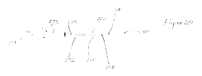
Figure 20 has a dental implant 260 and a non-contact tip 262 of a reader probe
263
(shown in Figure 23), both. of these components being in a sixth.
configuration for use of
the system of the invention,
The dental implant 260 has a non-contact RF1D tag 264, which is cylindrical in
shape,
positioned immovably inside an open cylindrical cavity 266 within the main
body of the
dental implant 260.
.20 The non-contact tip 262 of the reader probe 263 includes, at its
leading end, a. reader
antenna coil 268 (which is a transmitter receiver element in the form, of a
power coil), a
coil positioning spring 270 and a reader positioning collar 272. The reader -
antenna coil
26$ is electrically connected to, and receives its power through, wiring 27.3
from a
match circuit 274 along which current flows (as shown by the direction of the
arrows in
Figure 20).
The non-contact RFID tag 264 (as shown in more detail in Figures 21 and.22)
includes
a surface mounted coil inductor, hereinafter referred to as a tag antenna coil
276, and an
integrated circuit 278, both of which are mounted on a printed circuit board
280 and
coveted by a protective plastic moulding 282 which has high electrical
resistance.
CA 02977547 2017-08-23
WO 2016/134405 PCT/AU2016/000055
22.
in. use,. the contact tip 262 of the "powered on" reader probe 263 is inserted
through the
opening of the cavity 266 of the dental implant 260 until further insertion,
is prevented
by the reader positioning collar 272 becoming wedged in the opening, and the
tag
antenna coil 276 and the reader antenna coil 268 are .magnetic .field coupled.
The non-
contact RFID tan 264 is passively powered by electromagnetic wave
transmissions from
the reader antenna coil 268 of the reader probe and received by the tag
antenna coil 276.
As shown in Figure 23, the reader probe 263 has a handle 282 to which is
connected a
detachable nozzle 284 from which the non-contact tip 262 extends. As indicated
above,
the nozzle 284 is for use with the dental implant 260.
Figure 23 also shows a detachable nozzle 286 which can alternatively be
connected to
the handle 282, and from which a contact tip 288 extends. The nozzle 286 is
for use
with a dental. implant 290 as shown in, and to be hereinafter described with
reference
to, Fignre-24.
The dental implant identification system of the contact type shown
schematically in
Figure .24 has a dental implant 290 and the contact tip. 288 of the reader
probe 263
(shown. in Figure 23), both of these components being in a seventh
configuration for
use of the system of the invention.
The dental implant 290 has a contact RFED tag 292 (shown in Figure 25), which
is
cylindrical in shape, positioned immovably inside an open cylindrical. cavity
294 within
the main body of the dental implant 290.
The tip 288 of the-reader probe 263 includes a reader contact terminal 296 at
its leading
end, a terminal pressure spring 298, and a reader positioning collar 300. The
reader
contact terminal. 296 is electrically connected to, and receives its power
through, a
current supply wiring 301 from a secondary side of an electrical transformer
302, and
the reader positioning Collar 300 is electrically connected by a current
return wiring 303
to the transformer 302.
CA 02977547 2017-08-23
WO 2016/134405 PCT/AU2016/000055
23
The contact RFID tag 292 includes a printed circuit board 304 on which is
mounted an
integrated circuit 305 between two contact electrodes 306, 308. The printed
circuit
board 304 and the integrated circuit 305 are covered by a protective plastic
moulding.
309 which has a high electrical resistance. The contact electrode 306 presents
a. contact
surface in the shape of a conical depression facing towards the opening of the
cylindrical cavity 294, and the contact electrode 308 presents a contact
surface in the
shape of a conical projection facing towards, and abutting, the base (or
closed end) of
the dental implant. 290. Alternatively, the contact electrode 308 may .present
a contact
surface in the shape of a ring facing outwardly and abutting a cylindrical
wall region of
the cavity at the base of the dental implant 290.
In. use, the contact tip 288 of the "powered ore reader probe 263 is inserted
through the
opening of the cavity 294 of the dental implant 290, and the mader contact
terminal 296
is pressed against, or contacts, the contact electrode 306 of the contact
.RF1D tag 292
with low contact resistance and with a level of pressure regulated by the
terminal
pressure spring 298, until further insertion is prevented by the reader
positioning collar
300 becoming wedged in the opening. The interconnection of the aforementioned
components closes an electrical circuit along which current flows (as shown by
the
direction of the arrows in Figure 24) between the transformer 302 of the
reader probe
263 and:the contact. RYID tag 292. The transformer 302 is connected toa match
circuit
310.
The handle 282 of the reader probe 263 includes one or more buttons and -a
display,
such as an LED display, connected to a microcontroller for facilitating the
operation of
the reader probe 263 by the user. The reader probe 263 is connected by wired
or
wireless means to a personal: computer or other device operated through a
microprocessor, such as a smart phone.
The reader probe 263 is "powered on': by a suitable power source which
supplies power
to standard operating components for RED reader devices and either the match
circuit
274 or the match circuit 310, depending on whether the dental implant
identification.
CA 02977547 2017-08-23
WO 2016/134405 PCT/AU2016/000055
24
system is of the non-contact type or of the contact type, housed within the
reader probe
263.
Both the reader probe-263 of the portable reader device and either the
non,contact. RF1D
tag 264 or the contact MD tag 292, operate preferably in the 13.56 MHz ISM
band.
The main electronic components and circuitry design. of the reader probe 263
Which
utilizes the non-contact tip 262, and its interactions with the RFID tag 264
of the dental
implant 260 and with a desk top computer 62 and server 64 of the information.
processing means, are shown in Figure 26_ Reader probe 263 has a transceiver
extension / interface. circuit 312 which enables high performance
electromagnetic field
operation for extremely small sized RFID tags, such as tag 264, and also
includes the
match circuit 274 and the reader antenna coil 268 of the non-contact tip 262.
The main electronic. components and. circuitry design of the reader probe 263
which
utilizes the contact tip 288, and its interactions with the REID tag 292 of
the dental
implant 290 and with a desk top computer 62 and server 64 of the information
processing means, are shown in Figure 27_ Reader probe 263 has a transceiver
extension / interface circuit 312 which enables high performance
electromagnetic field
operation. for extremely small. sized RFID tags, such as tag 292, and also
includes the
match circuit 310, the transformer 302 and the reader contact terminal 296 of
the
contact tip 288.
The desk top computer 62 in both of the embodiments of Figures 26 and 27 could
alternatively be a. 'laptop" or "note book" or other computer, or even a
"tablet"
computer or a smart phone.
As will be apparent to the skil..led. addressee of this specification, with
the very large
number of different types or brands of dental implants that have been made
available,
the dental implant identification system of the present invention provides an
important
aid to the dental professional by assisting them to identify which dental
implant has
CA 02977547 2017-08-23
WO 2016/134405 PCT/AU2016/000055
been installed in a patient who requires restorative or other procedures on
the implant.
Not only can this infinmation be used at the clinical levd, it can also be
used for
inventory control, forensic identification and other types of investigation.
5 It will also be readily apparent to persons skilled in the art that
various modifications
may be made in details of design and construction of the embodiments of the
dental
implant identification system and-devices, and in the steps of using the
systems and
devices described above, without departing from the scope or ambit of the.
present
invent OIL
The reference in this specification, to any prior publication (or information
derived..fim
it), or to any matter which is known, is not, and should not be taken as an
acknowledgement or admission or. any form of suggestion that that prior
publication (or
information derived, from it) or known matter forms part of the common general
knowledge in the field of endeavour to which this specification relates before
the filing
date of this patent application.