Note: Descriptions are shown in the official language in which they were submitted.
CA 02977571 2017-08-23
1
SCREWING DEVICE AND SCREW
[0001] The present invention relates to a device for screwing a screw into
a substrate as well
as such a screw.
[0002] Screws usually have a fastening section for screwing the screw in a
direction of
placement into a substrate as well as having a head with a screw drive. There
are known screws,
which also have an attachment section for fastening a mounting part on the
screw, wherein the
attachment section is often embodied as a thread.
[0003] In some applications, it is desirable not to exceed or fall below a
predetermined
screwing depth of a screw into the substrate. To ensure the predetermined
screwing depth,
displacement limiters, which limit the forward advance of a screwing device
while screwing the
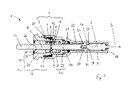
screw into the substrate, are used, so that the screw is disengaged from the
screwing device on
reaching the desired screwing depth. However, the design of such screwing
devices is extremely
complicated and they cannot otherwise be used for each individual application.
Furthermore, the
screwing depth cannot be predefined with the desired accuracy and changes over
time due to
wear, for example.
[0004] One object of the invention is to make available a device for
screwing a screw into a
substrate as well as such a screw, with which an accurate displacement
limitation is implemented
in a simple manner.
[0005] According to a first aspect of the invention, a device for screwing
a screw into a
substrate in a direction of placement comprises a coupling with a coupling
input that can be
driven to rotate and a coupling output, wherein the coupling input is
connected to the coupling
output in a torque-transmitting manner during the coupling state of the
coupling and in a
disengaged state of the coupling, the coupling input is freely rotatable with
respect to the
coupling output and wherein the coupling is disengaged when the coupling
output, starting from
a coupled state of the coupling, is moved away from the coupling input beyond
a predetermined
extent in the direction of placement of the coupling input. The coupling input
here has an
insertion end for insertion into a drill chuck of a screwing device. In
addition, the device
comprises a displacement limiter for limiting a movement of the coupling input
in the direction
of placement, wherein the displacement limiter has a substrate support for
contact with the
substrate and a stop for contact with the coupling input. The distance
measured in the direction
CA 02977571 2017-08-23
2
of placement between the substrate support and the stop is adapted to the
dimensions of the
coupling input, the coupling output and the screw, such that the coupling is
disengaged when the
screw has been screwed into the substrate by a certain predetermined depth of
placement. This
object is achieved by an adjusting device, by means of which the distance
between the substrate
support and the stop can be adjusted, as measured in the direction of
placement. In this way,
unwanted deviations from the predetermined screwing depth can be compensated.
[0006] A preferred embodiment is characterized in that the displacement
limiter comprises a
support part having the substrate support and a stop part including the stop,
wherein the adjusting
device comprises a first thread on the support part and a second thread on the
stop part, and
wherein the first thread and the second thread are screwed together, so that
twisting of the
supporting part with respect to the stop part will cause a change in the
measured distance in the
direction of placement between the substrate support and the stop, as measured
in the direction of
placement. The support part and/or the stop part especially preferably
comprise(s) a guide sleeve
for the screw.
[0007] A preferred embodiment is characterized in that the adjusting device
comprises a
catch device which engages at one or more different distances measured between
the substrate
support and the stop as measured in the direction of placement. This
counteracts any unwanted
misadjustment of the distance between the substrate support and the stop.
[0008] A preferred embodiment is characterized in that the coupling
comprises a coupling
spring which preloads the coupling in its disengaged state. A spring force of
the coupling spring
especially preferably acts on the coupling output and preloads the coupling
output away from the
coupling input.
[0009] A preferred embodiment is characterized in that the coupling input
comprises one or
more claws on the input end, and wherein the coupling output comprises one or
more claws on
the output end, and wherein the claws on the input end and the claws on the
output end engage in
one another for torque-transmitting connection of the coupling input to the
coupling output.
[0010] A preferred embodiment is characterized in that the coupling output
comprises the
head of the screw and wherein the coupling input comprises a receptacle for
the head. The head
of the screw is then disengaged directly from the receptacle. According to one
alternative
embodiment, the coupling output comprises a receptacle for the head of the
screw. The
CA 02977571 2017-08-23
3
receptacle is then disengaged from the coupling input together with the head
of the screw
accommodated therein. The receptacle especially preferably comprises a drive
bit, which is
preferably embodied as an internal polygon socket for transmitting torque from
the receptacle to
the head of the screw.
[0011] A preferred embodiment is characterized in that the receptacle has a
guide section
which becomes steadily wider in the direction of placement for guiding a
transitional section of
the screw connected to the head of the screw. The guide section especially
preferably becomes
wider conically in the direction of placement. Under some circumstances, a
guide for the screw
contributes to an improved constancy in the depth of placement of the screw
into the substrate.
[0012] A preferred embodiment is characterized in that the adjusting
direction comprises an
adjusting stop which limits an adjusting lift, i.e., a maximum displacement of
the adjusting
device. The stop part preferably has the adjusting stop. Alternatively the
support part has the
adjusting stop.
[0013] According to another aspect of the invention, a screw has a
fastening section for
screwing the screw into a substrate in the direction of placement, an
attachment section for
fastening a mounting part onto the screw and a head, which has a screw drive
that is preferably
embodied as an external polygon head. This object is achieved by a
transitional section, which
becomes steadily wider in the direction of placement and which is connected to
the head in the
direction of placement. The transitional section preferably becomes wider
conically in the
direction of placement. The screw can be guided on the transitional section,
which becomes
steadily wider and, under some circumstances, contributes toward an improved
constancy of the
screwing depth of the screw into the substrate.
[0014] A preferred embodiment is characterized in that one dimension of the
screw
transversely to the direction of placement, especially preferably at a right
angle to the direction
of placement becomes steadily larger from the head to the attachment section.
Preventing
unsteady locations results in facilitated guidance of the screw and under some
circumstances
leads to a reduction in jamming of the screw in the guide of the screwing
device.
[0015] A preferred embodiment is characterized in that the attachment
section has an
attachment thread for screwing the mounting part on the screw.
CA 02977571 2017-08-23
. ,
4
[0016] Preferred embodiments are explained in greater detail below with
reference to the
accompanying drawings, in which:
[0017] Figure 1 shows a device for screwing a screw into a substrate in the
direction of
placement in a longitudinal sectional view,
[0018] Figure 2 shows the device from Figure 1 in a partial longitudinal
sectional view as
well as in a cross-sectional view, and
[0019] Figure 3 shows a screw in a side view.
[0020] Figures 1 and 2 show a screwing device 1 for screwing a screw 2 into
a substrate (not
shown) in the placement direction 3. The screwing device 1 comprises a
coupling 4 with a
rotatably drivable coupling input 5 and a coupling output 6. The coupling
input 5 comprises a
drive shaft 8 with an insertion end 13 and a drive ring 7 which is preferably
fastened thereto by a
press fit and is rigidly connected thereto. The drive ring 7 has four claws 9
on the input end. The
coupling output 6 comprises an output shaft 10 with a receptacle 14 for a head
15 of the screw 2
and an output ring 11 which is preferably fastened thereto by a press fit and
is rigidly connected
thereto. The output ring 11 has four claws 12 on the output end. The
receptacle 14 has a guide
section 27, which steadily becomes wider conically in the direction of
placement 3, and serves to
guide the guide ring of a transitional section 28 of the screw connected to
the head 15 of the
screw 2. The receptacle 4 has an internal hexagon socket or a round internal
hexagon socket. The
head 15 of the screw 2 accordingly has an external hexagon head or a round
hexagon socket. A
magnet 37 is fastened in a recess, preferably in a bore in the output shaft,
so that the screw 2 is
held more securely in the receptacle 14 under some circumstances.
[0021] In particular to prevent any sticking of the claws on the input end
and the claws on
the output end, the claws on the input end and/or the claws on the output end
are provided with
an adhesive grease. In exemplary embodiments (not shown here), the coupling
input has one,
two, three or more than four claws on the input end, and the coupling output
accordingly has one,
two, three or more than four claws on the output end.
[0022] In addition, the screwing device 1 comprises a displacement limiter
16 for limiting
movement of the coupling input 5 in the direction of placement 3. The
displacement limiter 16
comprises a support part 17 with a substrate support 18 for contact with the
substrate (not shown)
as well as a stop part 19 with a stop 20 for contact with the coupling input
5. The stop 20 is
CA 02977571 2017-08-23
situated on a counter stop 26 of the drive shaft 8 opposite the direction of
placement. The support
part 17 has a guide sleeve 21, whose end face forms the substrate support 18
in the direction of
placement as well as having an internal thread 22. The stop part 19 has a
press-on sleeve 23,
whose end face forms the stop 20 opposite the direction of placement, and a
thread sleeve 25
with an external thread 24. The drive shaft 8 is mounted so that it can rotate
freely in the press-on
sleeve 23.
[0023] The coupling 4 is at least partially accommodated in the thread
sleeve 25 and
comprises a coupling spring 29, which preloads the coupling 4 in the
disengaged state, as
illustrated in Figure 1, in that a spring force of the coupling spring 29, on
the one hand, acts on
the coupling output 6, preferably on a first shoulder 30 of the coupling
output 6 facing opposite
the direction of placement 3 and, on the other hand, acts on the coupling
input 5, preferably on a
second shoulder 31, which faces in the direction of placement 3, on the
coupling input 5. The
coupling spring 29 presses the first shoulder 30 and the second shoulder 31
apart from one
another and thus preloads the coupling output 6 away from the coupling input
5.
[0024] For screwing the screw 2 into the substrate (not shown), first the
insertion end 13 is
inserted into a drill chuck of a screwing device (not shown) and is thereby
driven to rotate as
soon as the screwing device is turned on. Since the coupling 4 is preloaded by
the coupling
spring 29 in its disengaged state, only the coupling input 5 with the drive
shaft 8 and the drive
ring 7 having the claws 9 on the input end is driven to rotate. As soon as the
screwing
mechanism together with the screwing device 1 is pressed against the substrate
in such a way
that the substrate support 18 rests on the substrate, the spring force of the
coupling spring 29 is
overcome, so that the coupling input 5 moves toward the coupling output 6. As
soon as the claws
9 on the input end and the claws 12 on the output end mesh with one another, a
torque is
transferred from the coupling input 5 to the coupling output 6 and thus from
the screwing device
by way of the coupling 4 and the receptacle 14 to the screw 2, which is
ultimately screwed into
the substrate or into a prefabricated bore in the substrate.
[0025] During the entire screwing process, a predetermined distance between
the coupling
input 5 and the substrate is ensured by the displacement limiter 16, i.e., by
the distance between
the substrate support 18 and the stop 20 in the direction of placement 3. The
screw 2 with its
head 15 moves toward the substrate but the receptacle 14 conforms to the
advance of the screw 2
CA 02977571 2017-08-23
6
by means of the coupling spring 29. The screw 2 is driven to rotate over the
receptacle 14 until
the claws 12 on the output end are disengaged from the claws 9 on the input
end. The coupling
output 6 has then moved away from the coupling input 5 beyond a predetermined
extent in the
direction of placement 3. The distance between the substrate support 18 and
the stop 20 as
measured in the direction of placement is thereby adapted to the dimensions of
the coupling
input 5, the coupling output 6 and the screw 2, so that the coupling 4 is
disengaged precisely
when the screw 2 has been screwed into the substrate by a predetermined depth
of placement.
[0026] With the help of an adjusting device 32 comprising the internal
thread 22 and the
external thread 24, the distance between the substrate support 18 and the stop
20 is measured in
the direction of placement 3 screwing depth of the screw 2 into the substrate
can be adjusted. The
internal thread 22 and the external thread 24 are screwed together so that any
twisting of the
support part 17 with respect to the stop part 19 then causes a change in the
screwing depth. The
adjusting device additionally comprises an adjusting stop 38, which limits the
adjustment stroke
of the adjusting device 32 to 3 mm, for example. In the present case, the stop
part 19 has the
adjusting stop 38. In embodiments not shown here the support part has the
adjusting stop.
[0027] A catch device 33 serves to provide a lock during the adjustment of
the adjusting
device 32 and has a catch spring 34, which, on the one hand, is supported in
multiple recesses 35
on the inside of the support part 17 and, on the other hand, is supported onto
flattened areas 36
on the outside of the thread sleeve 25 of the stop part 19. For twisting of
the support part 17 with
respect to the stop part 19 a predetermined resistance force must be overcome
in order to deform
the catch spring 34 accordingly and allow it to engage in he next flattened
area 36.
[0028] Figure 3 shows one embodiment of a screw 51 in a side view drawn to
scale. The
bolt-shaped screw 51 comprises a fastening section 52 for screwing into a bore
in a substrate (not
shown) along a direction of placement 53 and an attachment section 54 for
arrangement outside
of the bore and a head 57 with a screw drive 55 formed as an external hexagon
head for applying
a torque to the screw 51. The fastening section 52 has a self-tapping thread
section 56 for
tapping, in particular cutting an internal thread into the bore. The
attachment section 54 has an
attachment thread 64 for screwing a mounting part (not shown) for example a
screw nut onto the
screw 51. The attachment thread has an outside diameter of 8 mm for example.
CA 02977571 2017-08-23
. . ,
7
[0029] The screw 51 additionally comprises a transitional section 58
which becomes wider
steadily in the direction of placement and is connected to the head 57 in the
direction of
placement 53. The attachment section 54 is again connected to the transitional
section 58 so that
the diameter of the screw 51 become steadily larger from the head 57 to the
attachment section
54 as measured in the direction of placement 53.
[0030] The fastening section 52 has a thread length in the direction
of placement 53 of 2.5
mm. The one-piece screw 51 consists of stainless steel which is preferably
inductively hardened
and/or is preferably stainless and has a material hardness of at least 800
MPa, for example 1,000
MPa. The attachment section 54 has a collar 59 with a stop 60 on which a
sealing element can be
arranged which seals the bore and/or the interspace between the bore and the
screw 51 with
respect to the surroundings after the fastening element has been fastened onto
the fastening
object. In embodiments which are not shown here, the fastening section is
connected directly to
the attachment thread without a collar in between. The thread length of the
fastening section then
amounts to 6.1 mm for example.
[0031] To manufacture the screw 51, the interface geometry 55 is
applied to a semifinished
product using a shaping method and a self-tapping thread for creating the
fastening section 52 is
applied to a semifinished product by using a rolling method. Next a bevel 63
is created on the
front end face of the semifinished product using a milling method wherein the
self-tapping thread
and the bevel 63 preferably overlap to form a thread lead-in and an external
thread.
[0032] The present invention has been illustrated on the example of a
screwing device but it
is pointed out that the device according to the invention is also suitable for
other intended
applications. In addition the features of the individual embodiments described
here may also be
combined in any desired manner within a single embodiment inasmuch as they are
not mutually
exclusively.