Note: Descriptions are shown in the official language in which they were submitted.
DUCT SYSTEM INCLUDING INFORMATION MODULES CONFIGURED TO EMIT
POSITIONAL INFORMATION AND METHOD OF THE SAME
This patent application is a divisional patent application of Canadian patent
application
no. 2,838,628 filed 7 January 2014.
1. Field
This present inventive concept relates generally to the field of conduit or
duct systems
for use in residential, commercial, industrial and other applications and, in
particular, to
a duct system including electronic information modules and methods for
improved
information gathering and mapping.
2. Background
Ducts are essential to a wide variety of structures including residential,
commercial,
industrial, and governmental structures. For example, they may carry water,
house fiber
optic cables or other communications or power lines, or participate in
critical pneumatic
systems aboard vehicles. Ducts often experience high volumes of throughput,
frequent
changes in positioning, connectivity or conducted materials, or other
conditions or
changes that require them to be locatable for maintenance and other activities
to be
performed.
3.
CA 2977693 2018-08-29
Existing duct systems are not designed so that individual duct lines can be
located with
ease and accuracy, particularly in applications where the lines are obscured
from sight
by obstructions such as soil in which such lines are buried. As such,
significant
expenses may be incurred in attempts to locate ducts, or in correcting work
done based
on erroneous information provided by or about existing duct systems. One
existing
method of locating a duct requires burying or otherwise placing a "tracer" or
similar wire
alongside the duct, for example during construction. Even though in certain
applications
the tracer wire may be attached to the duct before the duct is placed, there
are several
sources of potential error in using this method. These include the possibility
that the
positioning of the tracer wire on the duct will be disturbed during placement,
or that the
means for locating the tracer wire may hit on other metal objects and thus
provide false
positives for the location of the duct.
Further, in many existing systems, there remains the possibility that the
tracer wire or
similar device will become disassociated from the duct or otherwise damaged
during or
after the construction process, thus preventing accurate location of the duct.
Such
systems often have no economical way to provide redundancy in functionality,
and
failure of a tracer wire at any given location may cause failure of the entire
location
mechanism. Finally, there is no existing method for identifying individual,
obscured duct
sections or for obtaining similar specific information regarding the duct
system's location
.. and state.
The present inventive concept provides an improved duct system and a method
for
using same for mapping and location purposes.
2
29301417_1INATDOCS
CA 2977693 2017-08-29
SUMMARY
The following brief description is provided to indicate the nature of the
subject matter
disclosed herein. While certain aspects of the present inventive concept are
described
below, the summary is not intended to limit the scope of the present inventive
concept.
Embodiments of the present inventive concept provide an electronic module
housing
apparatus and method for attachment to a duct.
Certain exemplary embodiments can provide a device comprising: a) a duct; b) a
plurality of modules; and c) an oversheath covering the duct and the modules
such
that the modules are positioned between the duct and the oversheath, wherein
the
oversheath extends along the duct longitudinally such that the oversheath
defines a
trough between the modules, wherein the trough avoids contact with the duct
such
that an open space is defined between the trough and the duct.
Certain exemplary embodiments can provide a device comprising: a) a duct; b) a
first
module; c) a second module; and d) an oversheath covering the duct, the first
module, and the second module such that the first module and the second module
are positioned between the duct and the oversheath, wherein the duct, the
oversheath, the first module, and the second module define an open space,
wherein the open space contains a fluid which is able to cool at least one of
the first
module or the second module as the fluid flows through the open space.
3
CA 2977693 2019-02-26
Other embodiments provide, a duct system including a duct, at least one
information
module and an oversheath at least partially covering the information module
and fixing
the information module to the duct. The information module emits at least a
positional
signal permitting location of the information module based on the information
in the
positional signal alone or in combination with other information. The
information module
may also emit a duct properties signal regarding the condition of the duct
and/or its
contents. The duct system may be designed such that each information module is
within range of more than two other information modules, thus providing
redundancy in
systems where signals are exchanged between information modules in a
"network",
and allowing for continued routing of signal information along such a network
of
information modules even where one information module is malfunctioning or
inoperable. Such a network may simply bypass the malfunctioning or inoperable
information module and pass signal information over it to the next functioning
module.
A method of using the duct system for mapping and/or location efforts is also
disclosed
herein. The steps of the method include providing at least one information
module fixed
to a duct that is configured to emit a positional signal, receiving, via a
receiver, the
3a
CA 2977693 2019-02-26
positional signal from the information module, and plotting the positional
signal from the
information module on at least two axes.
The information module may further be configured to emit a duct properties
signal
relating to at least one of i) the condition of the duct, and ii) the contents
of the duct, and
the method may further include the step of receiving, via the receiver, the
duct
properties signal.
The duct properties signal information may be used separately or following
correlation
with the positional signal information. The information contained in signals
may
ultimately pass from the information module to a user or computer system
configured to
process and/or plot such information.
Additional aspects, advantages, and utilities of the present invention will be
set forth in
part in the description which follows and, in part, will be obvious from the
description, or
may be learned by practice of the present invention.
BRIEF DESCRIPTION OF THE DRAWINGS
Embodiments of the present inventive concept are described in detail below
with
reference to the attached drawing figures, wherein:
FIG. 1 is an enlarged front cross sectional perspective of the embodiment of
FIG. 2
illustrating an information module attached to a duct using an oversheath.
FIG. 2 is a side view of a duct system according to an embodiment of the
present
.. inventive concept including multiple information modules secured along the
length of a
duct by an oversheath.
4
29301417 1INATDOCS
CA 2977693 2017-08-29
The drawing figures do not limit the present inventive concept to the specific
embodiments disclosed and described herein. The drawings are not necessarily
to
scale, emphasis instead being placed upon clearly illustrating the principles
of the
present inventive concept.
DETAILED DESCRIPTION
The following detailed description of the invention references the
accompanying
drawings that illustrate specific embodiments in which the invention can be
practiced.
The embodiments are intended to describe aspects of the invention in
sufficient detail to
enable those skilled in the art to practice the invention. Other embodiments
can be
utilized and changes can be made without departing from the scope of the
present
invention. The following detailed description is, therefore, not to be taken
in a limiting
sense. The scope of the present invention is defined only by the appended
claims,
along with the full scope of equivalents to which such claims are entitled.
In this description, references to "one embodiment", "an embodiment", or
"embodiments" mean that the feature or features being referred to are included
in at
least one embodiment of the technology. Separate references to "one
embodiment", "an
embodiment", or "embodiments" in this description do not necessarily refer to
the same
embodiment and are also not mutually exclusive unless so stated and/or except
as will
be readily apparent to those skilled in the art from the description. For
example, a
feature, structure, act, etc. described in one embodiment may also be included
in other
embodiments, but is not necessarily included. Thus, the present technology can
include
a variety of combinations and/or integrations of the embodiments described
herein.
5
29301417_1INATDOCS
CA 2977693 2017-08-29
Turning to FIG. 1, a single electronic information module 10 is illustrated
from a front
cross sectional perspective at line 1 of the embodiment of FIG. 2. The
information
module 10 is fixed to an exterior surface of a duct 12 using an oversheath 14.
The
information module 10 abuts the exterior surface of the duct 12 but is not
embedded in
the duct 12, thus preserving the structural integrity of the duct 12. The
methods of
installing information modules onto a duct or series of ducts of the present
inventive
concept may vary. In the preferred installation method, information modules
are
attached to the exterior of the duct at desired increments along its length
using an
adhesive or heat treatment. This assembly is processed through a die that
applies an
oversheath around the duct and information module assembly.
Though the material and thickness used for an oversheath may vary, the
oversheath is
preferably composed primarily of plastic such as a polyethylene plastic and is
anywhere
between .5-.7" in thickness. Such thickness may be decreased for improved
signal
strength or smaller effective bulk of the duct, or increased to improve
durability, e.g., in
rough or rockier terrains. The oversheath may be heated prior to application
to the
information module and duct assembly to increase elasticity. Once applied to
the
assembly, the oversheath may be allowed to cool and constrict, thereby
securing the
information modules against the exterior of the duct.
Returning to FIG. 1, the information module 10 and duct 12 are surrounded by
an
oversheath 14 that wraps around a substantial portion of the exterior of the
duct 12. On
a portion of the duct's 12 surface that faces the information module 10, the
oversheath
14 raises off from the exterior of the duct 12 to wrap around the exterior of
the
information module 10 and fix the information module 10 to the duct 12. In
embodiments
6
29301417_1INATDOCS
CA 2977693 2017-08-29
where the oversheath does not settle flush against the exterior of the duct
and
information module at the point where they interface, like in FIG. 1, pockets
may form
and provide additional benefits in the system, for example by providing space
through
which air or other fluids may flow to enhance cooling of the information
modules. In
other embodiments, the oversheath may contact an even greater proportion of
the
exterior of the duct, for example in embodiments where the oversheath is
composed at
least partially of heated plastic which is allowed to settle along the
contours of the
information module during construction of the apparatus, and which thereafter
cools to
secure the information module against the duct.
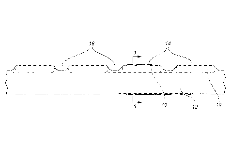
Turning now to FIG. 2, a duct system of an embodiment of the present inventive
concept is shown from a side perspective. The system includes multiple
information
modules 10 spaced linearly along the length of a duct 12. The upper and lower
extremities of the duct 12 are illustrated using broken lines in FIG. 2. An
oversheath 14
wraps around the exteriors of the information modules 10 and duct 12, and
secures the
information modules 10 to the exterior of the duct 12. Depending on the
conditions
during installation in various embodiments, including the incremental spacing
of the
information modules along the duct, the thickness of the information modules,
and other
factors, this method of installing the information module housing apparatus
onto a duct
will produce troughs between the information modules, such as the troughs 16
illustrated in FIG. 2. The troughs 16 may be utilized in handling the duct 12
during
installation, and may contribute to the electromagnetic characteristics of the
assembled
duct system, such as those characteristics that are detected as part of the
transmission
of signals from the information module to a receiver. Further, though the
embodiment of
7
29301417_1INATDOCS
CA 2977693 2017-08-29
FIG. 2 is illustrated with information modules 10 arranged linearly along the
exterior of
the duct 12, it is foreseen that the information modules 10 may be
alternatively placed
along the outer surface of the duct 12, for example in a non-patterned fashion
at
different points on the circumference of the duct.
The information modules may transmit or emit information in signals such as
radio
transmissions, electronic currents through wires, or through other known
means, and
may do so actively on an intermittent or continuous basis or passively, for
example in
response to interrogation by a receiver. A "receiver" is a means for
collecting signals
from the information modules of the system of the present inventive concept,
and may
.. be integrated within one or more information modules or may be separate
devices
configured for receipt of the signals. A signal "range" refers to the maximum
effective
distance between a receiver and an information module within which the
receiver is
capable of receiving a signal from the information module, and depends on a
number of
factors such as signal strength, sophistication of the receiver, and number
and type of
interceding obstructions. The receiver may transmit signals obtained from the
information modules to a user or to a separate piece of equipment, and may
optionally
perform further processing on the signals prior to any such transmission.
An "information module" is electronic and emits a positional signal that
includes at least
one of information i) that enables location of the information module with
respect to
another object, e.g., the receiver, on at least two axes, ii) regarding the
coordinates of
the information module on at least two axes, and iii) associated with the
particular duct
section to which the information module is fixed. Any or all of the foregoing
items of
information may be used for locating and/or mapping a duct system. In a
preferred
8
29301417_1INATDOCS
CA 2977693 2017-08-29
embodiment, a handheld receiver may be passed within the range of signal
detection
for the information modules of the duct system and will collect at least one
of the
foregoing types of information. Depending on the scope of the location or
mapping
needed, a user may then use the positional signals collected through the
receiver to
locate a particular duct section, or map an entire duct system. In certain
embodiments,
this may require processing the positional signals with other information, for
example
regarding relative position of another object, such as the receiver itself.
A receiver may also be integrated into one or more of the information modules,
permitting positional signals to be exchanged between the information modules
themselves in a network, for example to enable the calculation of relative
positions
amongst the information modules of the duct system. This embodiment may
further
provide for collection of positional signal information from the entire duct
system by a
receiver that is only within the positional signal range of one information
module, for
example because that information module has collected the positional signal
information
from the other information modules of the duct system that are within the
network. Thus,
in certain embodiments it may be preferable for any one information module to
be within
the positional signal range of at least four other information modules, e.g.,
with two on
either side, to enable continued transmission of positional signals along the
information
module network even where one information module becomes inoperable and
requires
replacement or maintenance and is bypassed by the network.
In more sophisticated embodiments of the system, the information modules may
further
be configured to emit duct properties signals including information regarding
at least
one of: i) the condition of the duct, and ii) the contents of the duct. The
information
9
29301417_11NATDOCS
CA 2977693 2017-08-29
module may be configured with its own sensor(s) to detect such duct properties
information or may simply receive such information from independent sensor
apparatus(es). Information regarding the condition of the duct may relate to
the integrity
of the duct, the history of information exchange with receivers of the duct
system, the
features of the duct including valves or circuitry in proximity thereto, or
other properties
and characteristics. Information regarding the contents of the duct may
include
volumetric flow rate, pressure, electrical properties or performance
information, or other
properties or characteristics.
The duct system of the present inventive concept thus provides means for
collecting
information regarding the position of its constituent duct and/or duct
sections and,
optionally, regarding the condition and/or operation of the duct sections and
their
contents. This information can be mapped for ease of location and maintenance.
Having now described the features, discoveries and principles of the general
inventive
concept, the manner in which the general inventive concept is constructed and
used,
the characteristics of the construction, and advantageous, new and useful
results
obtained; the new and useful structures, devices, tools, elements,
arrangements, parts
and combinations, are set forth in the appended claims.
It is also to be understood that the following claims are intended to cover
all of the
generic and specific features of the general inventive concept herein
described, and all
statements of the scope of the general inventive concept which, as a matter of
language, might be said to fall therebetween.
29301417_1INATDOCS
CA 2977693 2017-08-29