Note: Descriptions are shown in the official language in which they were submitted.
CA 02977922 2017-08-25
Docket No. PJFA-17283-PCT
1
DESCRIPTION
STEEL PIPE, STEEL PIPE STRUCTURE, METHOD FOR MANUFACTURING
STEEL PIPE, AND METHOD FOR DESIGNING STEEL PIPE
Field
[0001] The present invention relates to a steel pipe, a
steel pipe structure, a method for manufacturing a steel
pipe, and a method for designing a steel pipe.
Background
[0002] In recent years, gas fields and oil fields are
newly developed in abundance due to an increase in demand
for gas and petroleum. There are increasing opportunities
to embed pipelines for transporting gas and petroleum in
earthquake-prone areas and non-permafrost areas. However,
in such earthquake-prone areas and non-permafrost areas,
the ground may be moved due to various causes such as
liquefaction, fault displacements, frost heaving, and
thawing, and the pipelines may be deformed accordingly.
Further, when a pipeline is deformed significantly, steel
pipes structuring the pipeline are bent so as to buckle on
the compression side and to subsequently break on the
tensile side. With these circumstances in the background,
techniques for improving deformability of steel pipes so
that the steel pipes bend without buckling have been
proposed from a viewpoint of preventing damages in the
buckling part and preventing leakage of gas or petroleum
from the broken part. More specifically, Patent Literature
1 describes a technique for improving the deformability of
a steel pipe by arranging a wavelength ratio (the
wavelength of a waveform shape / a Timoshenko's buckling
wavelength) of the waveform shape (undulation) to be 0.8 or
smaller, the waveform shape being formed by outer diameters
along the longitudinal direction of the steel pipe through
a pipe expansion process.
CA 02977922 2017-08-25
Docket No. PJFA-17283-PCT
2
Citation List
Patent Literature
[0003] Patent Literature 1: Japanese Patent No. 5447461
(see claim 1 and paragraph 0044)
Summary
Technical Problem
[0004] According to the technique described in Patent
Literature 1, while the amplitude of the waveform shape is
arranged to have a constant value throughout (0.73 mm
0.06% of OD, where "OD" denotes the diameter of the steel
pipe), the range of the wavelength ratio of the waveform
shape that can improve the deformability of the steel pipe
is defined. However, as a result of extensive studies, the
inventors of the present invention have discovered that,
even when the wavelength ratio of the waveform shape is in
the abovementioned range, the deformability of steel pipes
may be lowered in some situations depending on the value of
the amplitude of the waveform shape. Further, generally
speaking, the smaller the wavelength ratio of a waveform
shape is, the shorter is the forwarding pitch of the die in
the longitudinal direction of the steel pipe during the
pipe expansion process. Therefore, when the technique
described Patent Literature 1 is used, the labor and time
required by the pipe expansion process increase in
accordance with the improvement of the deformability of the
steel pipe. For this reason, there is a demand for a
technique that is able to improve the deformability of
steel pipes while reducing the labor and time required by
the pipe expansion process.
[0005] In view of the circumstances described above, it
is an object of the present invention to provide a steel
pipe, a steel pipe structure, a method for manufacturing a
steel pipe, and a method for designing a steel pipe with
3
which it is possible to improve the deformability while
reducing the labor and time required by the pipe expansion
process.
Solution to Problem
[0006] A steel pipe according to the present invention
has a waveform shape formed on an outer diameter thereof by
a pipe expansion process. Further, a value "a/w" is 0.038%
or less, where "a" and "w" denote an amplitude and a
wavelength of the waveform shape, respectively.
[0007] According to the steel pipe according to the
present invention, in the above invention, a value "w/X"
indicating a ratio of the wavelength "w" of the waveform
shape to a Timoshenko's buckling wavelength "X" is larger
than 0.8.
[0008] A steel pipe structure according to the present
invention is formed by using the steel pipe according to
the present invention. The steel pipe structure includes,
for example, a pipeline, a steel pipe pile, a steel pipe
sheet pile, and a water gate penstock.
[0009] A method for manufacturing a steel pipe according
to the present invention is a method for manufacturing a
steel pipe that has a waveform shape formed on an outer
diameter thereof by a pipe expansion process. Further, the
pipe expansion process includes a step of forming the
waveform shape in such a manner that a value "a/w" is
0.038% or less, where "a" and "w" denote an amplitude and a
wavelength of the waveform shape, respectively.
[0010] The present invention also relates to a steel
pipe as described above, that has a waveform shape formed
on an outer diameter thereof by a pipe expansion process,
wherein a relationship between a ratio "w/k" and a
CA 2977922 2019-01-25
4
buckling-time bending angle determined according to
Expression (1) presented below, the ratio "w/X" indicating
a ratio of a wavelength "w" of the waveform shape to a
Timoshenko's buckling wavelength "k", the wavelength "w"
and an amplitude "a" of the waveform shape is determined on
a basis of a result of:
The buckling -time bending angle
= (Dl + D2)/2 +(D1 - D2)/2 *tan11((- X + 0/13) (1)
where parameters "Dl", "D2", "a", and "P" in Expression (1)
have values that are determined by the outer diameter and a
thickness of the steel pipe to be manufactured.
Advantageous Effects of Invention
[0011] By using any of the steel pipe, the steel pipe
structure, the method for manufacturing a steel pipe, and
the method for designing a steel pipe according to the
present invention, it is possible to improve the
deformability while reducing the labor and time required by
the pipe expansion process.
Brief Description of Drawings
[0012] FIG. 1 is a drawing illustrating an example of an
outside diameter shape of a steel pipe.
FIG. 2 is a schematic drawing for explaining a bending
buckling phenomenon of a steel pipe.
FIG. 3 is a chart illustrating a result of an analysis
performed on strains exhibited at the time of buckling
(hereinafter, "buckling-time strains") of a steel pipe
having an outside diameter of 20 inches and a thickness of
15.9 mm and another steel pipe having an outside diameter
of 48 inches and a thickness of 22 mm.
FIG. 4 is a chart illustrating a graph obtained by
normalizing the horizontal axis in FIG. 3 by using a
CA 2977922 2019-01-25
CA 02977922 2017-08-25
Docket No. PJFA-17283-PCT
buckling wavelength and by normalizing the vertical axis in
FIG. 3 by using the buckling-time strain observed when a
wavelength is equal to 0.
FIG. 5 is a chart indicating a relationship between
5 wavelengths and amplitude ratios.
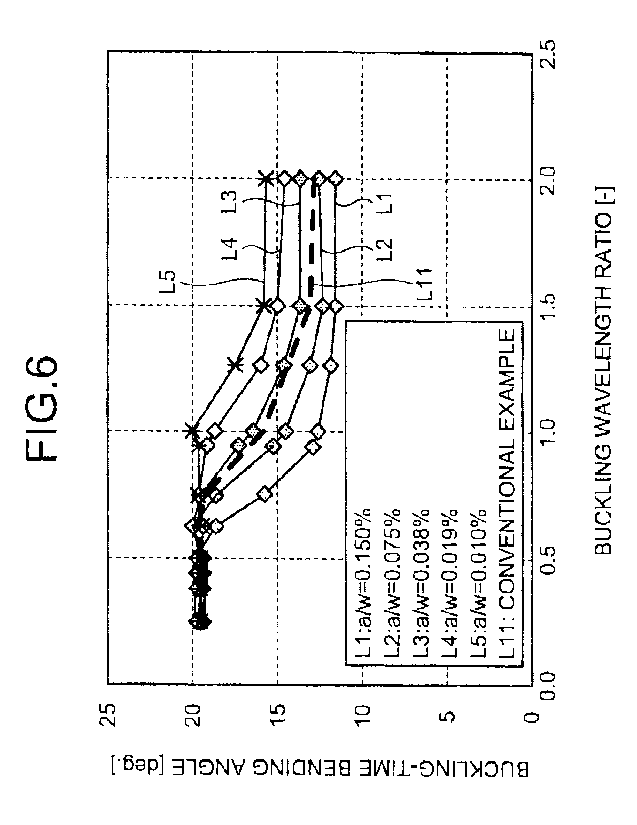
FIG. 6 is a chart illustrating a relationship between
buckling wavelength ratios and bending angles at the time
of buckling (hereinafter, "buckling-time bending angles")
corresponding to values of a design factor a/w.
FIG. 7 is a chart illustrating a relationship between
the buckling wavelength ratios and the buckling-time
bending angles.
Description of Embodiments
[0013] To evaluate buckling phenomena occurring in the
vicinity of a welded joint part of a steel pipe, the
inventors of the present application performed a bending
test on a steel pipe (a UOE steel pipe having an outside
diameter of 48 inches (1,219 mm) and a thickness of 22 mm)
having a welded joint part. When the outside diameter
shape of the steel pipe was measured prior to the bending
test, the outside diameter shape of the steel pipe appeared
to be a waveform shape and exhibited variances. The
variances were caused by a pipe expansion process performed
on the steel pipe. The wavelength of the waveform shape
was similar to the forwarding cycle of a die used in the
pipe expansion process. All the amplitude values of the
waveform shape were substantially equal to one another and
were caused by a constant mechanical diameter-expanding
process. FIG. 1 illustrates the outside diameter shape of
the steel pipe that was measured. In FIG. 1, the point at
which the position in the longitudinal direction is "0"
corresponds to the position of the welded joint. In the
example illustrated in FIG. 1, the wavelength of the
CA 02977922 2017-08-25
Docket No. PJFA-17283-PCT
6
waveform shape was approximately 400 mm.
[0014] FIG. 2 illustrates an overview of a bending
buckling phenomenon of a steel pipe. In some situations, a
steel pipe P may exhibit a bending buckling phenomenon as
illustrated in FIG. 2, when having gone through a
significant deformation (a bending moment) due to
liquefaction of the ground or moving of a fault. Thus, to
study a bending deformation amount of a steel pipe that can
be tolerated before the occurrence of the bending buckling
phenomena, a plurality of analysis models were created by
varying the wavelength of the waveform shape, so as to
compare deformability characteristics by using the analysis
models. FIG. 3 illustrates a result of the analysis
performed on strains exhibited at the time of buckling
(hereinafter, "buckling-time strains") of a steel pipe
having an outside diameter of 20 inches and a thickness of
15.9 mm and another steel pipe having an outside diameter
of 48 inches and a thickness of 22 mm. In FIG. 3, the
vertical axis expresses a buckling-time strain (a moving-
average strain at the time of buckling), whereas the
horizontal axis expresses the wavelength of the waveform
shape applied to each of the analysis models.
[0015] The buckling-time strain has a proportional
relationship with the deformation amount and the curvature
of a steel pipe. In other words, a steel pipe that buckles
with a small deformation amount or a small curvature (i.e.,
a steel pipe having a small buckling-time strain) has a low
degree of deformability. Conversely, a steel pipe that did
not buckle until a large deformation amount or a large
curvature was exhibited (i.e., a steel pipe having a large
buckling-time strain) has a high degree of deformability
and is therefore considered to be applicable to a severe
environment such as an earthquake-prone area.
CA 02977922 201.7.5
Docket No PJFA-17283-POT
7
[0016] As illustrated in FIG. 3, for both the steel pipe
having an outside diameter of 20 inches and a thickness of
15.9 mm and the other steel pipe having an outside diameter
of 48 inches and a thickness of 22 mm, the smaller the
wavelength of the waveform shape is, the larger the
buckling-time strain becomes. Also, when the wavelength of
the waveform shape is small to a certain extent, a
buckling-time strain equal to or larger than a certain
value is exhibited. Further, as the wavelength of the
waveform shape increases, the buckling-time strain
decreases with an S-shaped plot line at a certain threshold
value. These characteristics indicate that it is possible
to provide a steel pipe having an excellent level of
deformability by arranging the wavelength of the waveform
shape to be equal to or lower than the certain threshold
value.
[0017] Accordingly, the analysis result in FIG. 3
comparing the two steel pipes having the mutually-different
outer diameters and the mutually-different thicknesses with
each other was normalized. FIG. 4 illustrates a graph
obtained by normalizing the horizontal axis in FIG. 3 by
using a buckling wavelength k (where "X" denotes the
Timoshenko's buckling wavelength) and by normalizing the
vertical axis in FIG. 3 by using the buckling-time strain
observed when the wavelength is equal to 0. As illustrated
in FIG. 4, between the steel pipe having an outside
diameter of 20 inches and a thickness of 15.9 mm and the
other steel pipe having an outside diameter of 48 inches
and a thickness of 22 mm, the relationship is substantially
the same between the buckling-time strain and the ratio of
the wavelength of the waveform shape to the buckling
wavelength 2 (i.e., the wavelength of the waveform shape /
CA 02977922 201.7.5
Docket No. PJFA-17283-PCT
8
the buckling wavelength X; hereinafter, "buckling
wavelength ratio").
[0018] On the basis of this relationship, it is possible
to maintain the buckling-time strain at a high level, by
arranging the buckling wavelength ratio to be within a
range less than or equal to 0.50. Further, when the
buckling wavelength ratio becomes approximately 1.0, the
buckling-time strain becomes equivalent to the buckling-
time strain exhibited when the buckling wavelength ratio is
larger than 1.0, so as to be as low as approximately 65% of
the buckling-time strain exhibited when a steel pipe has a
buckling wavelength ratio of 0.5 or smaller.
[0019] To shorten the wavelength of the waveform shape,
an effective method is to press a die in an overlapping
manner so that, during the pipe expansion process, the
positions onto which the die is pressed are overlapped in
the longitudinal direction of the steel pipe. Accordingly,
by using steel pipes each having an outside diameter of 24
inches, an evaluation was made on the waveform shape formed
by outer diameters, with respect to a steel pipe to which
the overlapping die pressing was applied and another steel
pipe to which the overlapping die pressing was not applied.
In this situation, the effective length of the die was
approximately 450 mm. During the pipe expansion process,
the one pipe was prepared by pressing the die with a pitch
of 450 mm, and the other pipe was prepared by pressing the
die with a smaller pitch of 80 mm (by pressing the die five
or six times per effective length).
[0020] As a result, it was confirmed that the waveform
shape formed on the outer diameters is dependent on the
manner in which the die is pressed on the steel pipe. More
specifically, during the pipe expansion process, the steel
pipe on which the die was pressed with the pitch of 450 mm
CA 02977922 201.7.5
Docket No PjFA-17233-PCT
9
had a waveform shape of which the wavelength was
approximately 430 mm to 450 mm. In contrast, during the
pipe expansion process, the steel pipe on which the die was
pressed with the pitch of 80 mm had a waveform shape of
which the wavelength was approximately 60 mm to 70 mm.
Further, it was also confirmed that the manner in which the
die is pressed on the steel pipe also has an impact on the
amplitude of the waveform shape and that the smaller the
pitch for the pressing of the die is, the smaller is the
amplitude of the waveform shape is.
[0021] Accordingly, the inventors of the present
invention evaluated relationships between wavelengths and
amplitudes of the waveform shape. FIG. 5 is a chart
indicating a relationship between wavelengths and amplitude
ratios. As indicated in FIG. 5, wavelengths and amplitudes
of the waveform shape are in a proportional relationship
with each other. Consequently, it is safe to say that it
is possible to improve the deformability of steel pipes by
pressing the die finely with a smaller pitch. For this
reason, the inventors of the present invention regarded a
ratio "a/w" of the amplitude "a" to the wavelength "w" of
the waveform shape as a new design factor and evaluated
impacts made on the deformability by values of the design
factor a/w.
[0022] FIG. 6 is a chart illustrating a relationship
between buckling wavelength ratios and bending angles at
the time of buckling (hereinafter, "buckling-time bending
angles") corresponding to values of the design factor a/w.
As illustrated in FIG. 6, it was observed that the buckling
wavelength ratio to reach the maximum value (approximately
20 degrees in the present example) of the buckling-time
bending angle was different for the values of the design
factor a/w, and it was confirmed that the buckling-time
CA 02977922 2017-08-25
Docket No. PJFA-17283-PCT
bending angle increases as the value of the design factor
a/w decreases. Further, the inventors of the present
invention evaluated a relationship between buckling
wavelength ratios and buckling-time bending angles, derived
5 from the technique described in Patent Literature 1. As a
result, as indicated by a feature line L11 in FIG. 6, it
was confirmed that the buckling-time bending angle based on
the technique described in Patent Literature 1 is smaller
than the buckling-time bending angle that is indicated by a
10 feature line L3 and that corresponds to the situation where
the value of the design factor a/w is equal to 0.038%.
[0023] The above notion signifies that, by arranging the
value of the design factor a/w to be equal to or smaller
than 0.038%, and preferably by arranging the value of the
design factor a/w to be equal to or smaller than 0.038%
while arranging the buckling wavelength ratio to be larger
than 0.8, it is possible to achieve the buckling wavelength
ratio required by realizing the buckling-time bending angle
described in Patent Literature 1, i.e., it is possible to
increase the die forwarding amount during the pipe
expansion process. Accordingly, by adjusting the
wavelength and the amplitude of the waveform shape so as to
arrange the value of the design factor a/w to be equal to
or smaller than 0.038%, it is possible to improve the
deformability while reducing the labor and time required by
the pipe expansion process.
[0024] By generalizing the feature lines indicated in
FIG. 6, it is possible to express the relationship between
the buckling-time bending angle and the buckling wavelength
ratio X as indicated in Expression (1) presented below. In
this situation, as illustrated in FIG. 7, the parameters D1
and D2 in Expression (1) denote the maximum value and the
minimum value of the buckling-time bending angle,
CA 02977922 2017-08-25
Docket No. PJFA-17283-PCT
11
respectively. The parameter a is a parameter indicating
the buckling wavelength ratio at a point P where the value
of the buckling-time bending angle is equal to (D1 + 02) /
2. The parameter p is a parameter indicating the degree of
inclination (the slope) observed when the value of the
buckling-time bending angle decreases from the maximum
value to the minimum value. Each of the values of the
parameters D1, D2, a, and p is dependent on the outside
diameter and the thickness of the steel pipe. A steel pipe
having a high level of deformability satisfies the
conditions where the value of the parameter D1 is large and
where the buckling wavelength ratio (w/2) of the waveform
shape, which is characteristic to UOE steel pipes, is small.
When the wavelength of the waveform shape is not controlled
and is sufficiently long, the deformability may decrease
down to the parameter D2. To control the wavelength of the
waveform shape during the manufacturing process so as to
bring the level of deformability close to the maximum
deformability D1 that can be achieved by a steel pipe, it
is necessary to keep the value of the parameter a small.
Theoretically, for example, when the buckling wavelength
ratio (w/A) is equal to the value of the parameter a, the
level of deformability corresponds to the intermediate
value between the parameter D1 and the parameter D2. When
the user wishes to improve the deformability from the
lowest value represented by the parameter D2, even by as
little as 10% of the room for growth expressed as (D1 - D2),
it is a good idea to select (-X + a) / p = 1.1 which
corresponds to the situation where the value of tanh((-X +
a) / p) calculated from Expression (1) is equal to -0.4.
It is considered that the deformability required of steel
pipes varies depending on impacts made on public safety and
CA 02977922 2017-08-25
Docket No PJFA-17283-PCT
12
environment conservation by buckling and destructing
phenomena exhibited thereby. Further, exercising control
so as to keep the buckling wavelength ratio (w/X) small,
i.e., exercising control finely on the wavelength of the
waveform shape of a steel pipe, usually makes the pipe
expansion process longer and may cause a disadvantage in
terms of productivity. By using the mathematical
expression presented below, it is possible to control the
manufacturing method to realize a required level of
deformability. It is therefore possible to provide a steel
pipe product having a cost advantage, by realizing a level
of deformability that is both necessary and sufficient.
[0025]
The buckling- time bending angle
= (DI + D2)/2 + (DI - D2)/2 * tanti((- X + a)/ 13) (1)
[0026] Accordingly, it is possible to design a steel
pipe of which it is possible to improve the deformability
while reducing the labor and time required by the pipe
expansion process, by preparing values of the parameters D1,
D2, a, and p for each of the various outer diameters and
the thicknesses of steel pipes in advance through an
experiment or an analysis, subsequently reading such values
of the parameters D1, D2, a, and p that correspond to the
outside diameter and the thickness of a steel pipe to be
manufactured, further evaluating the relationship between
the buckling-time bending angle and the buckling wavelength
ratio X by constructing Expression (1) while using the read
values, and determining the wavelength and the amplitude of
the waveform shape of the steel pipe to be manufactured on
the basis of the result of the evaluation. Further, by
performing the pipe expansion process according to the
determined buckling wavelength ratio, it is possible to
CA 02977922 2017-08-25
Docket No. PJFA-17283-POT
13
manufacture a steel pipe in which the deformability is
improved, while reducing the labor and time required by the
pipe expansion process. The steel pipe of the present
invention is applicable to a steel pipe structure such as a
pipeline, a steel pipe pile, a steel pipe sheet pile, a
water gate penstock, or the like.
[0027] A number of embodiments have thus been explained
to which the invention conceived of by the inventors of the
present application is applied. However, the present
invention is not limited to the text and the drawings
presented in the embodiments to represent a part of the
disclosure of the present invention. In other words, other
modes of carrying out the invention, other embodiments,
operation techniques, and the like that can be arrived at
by a person skilled in the art or the like on the basis of
the described embodiments all fall within the scope of the
present invention.
Industrial Applicability
[0028] According to the present invention, it is
possible to provide the steel pipe, the steel pipe
structure, the method for manufacturing a steel pipe, and
the method for designing a steel pipe with which it is
possible to improve the deformability while reducing the
labor and time required by the pipe expansion process.
Reference Signs List
[0029] P STEEL PIPE