Note: Descriptions are shown in the official language in which they were submitted.
DEGAUSS CIRCUIT FOR USE IN AN
ELECTRONICALLY ACTUATED DOOR LOCK
RELATIONSHIP TO OTHER APPLICATIONS AND PATENTS
[0001] The present application claims the benefit of U.S. Provisional
Patent
Application No. 62/385,672, filed September 9, 2016.
TECHNICAL FIELD
[0002] The subject matter disclosed herein relates to the field of
electromagnetics
and more particularly relates to a degauss circuit for an electromagnet such
as found in
electronically actuated door locks.
BACKGROUND OF THE INVENTION
[0003] Electromagnetic locks, also referred to as maglocks, are well known
locking devices that consist of an electromagnet and an armature plate. There
are two
main types of electric locking devices. Locking devices can be either "fail
safe" or "fail
secure". A fail-secure locking device remains locked when power is lost. Fail-
safe
locking devices are unlocked when de-energized. Direct pull electromagnetic
locks are
inherently fail-safe. Typically, the electromagnet portion of the lock is
attached to the
door frame and a mating armature plate is attached to the door. The two
components
are in contact when the door is closed. When the electromagnet is energized, a
current
passing through the electromagnet creates a magnetic flux that causes the
armature
plate to attract to the electromagnet, creating a locking action. Because the
mating area
of the electromagnet and armature is relatively large, the force created by
the magnetic
flux is strong enough to keep the door locked even under stress. Typical
single door
1
=
CA 2978563 2017-09-08
electromagnetic locks are available with up to 1500 pounds dynamic holding
force
capabilities.
[0004] The magnetic lock relies upon the basic concepts of
electromagnetism.
Essentially, it consists of an electromagnet attracting a conductor with a
force large
enough to prevent the door from being opened. More specifically, the device
makes use
of the fact that a current through one or more loops of wire, i.e. a solenoid,
produces a
magnetic field. This works in free space, but if the solenoid is wrapped
around a
ferromagnetic core such as soft iron the effect of the field is greatly
amplified. This is
because the internal magnetic domains of the material align with each other to
greatly
enhance the magnetic flux density.
[0005] As mentioned, an electromagnetic lock operates under the premise of
running an electric current though copper coils that surround a solid or
laminate core of
some ferrous material. This operation produces a magnetic field that permeates
the
core, and when the strike plate is introduced to the electromagnet, maximum
magnetic
holding force is created.
[0006] When the current through the coil is removed, the magnetic field
collapses, but the core material maintains some amount of residual magnetism
that
continues to attract the strike plate. In the lock industry, this residual
magnetism is not
desired. Building code requirements often stipulate that the strike must be
able to be
separated from the electromagnet with minimal amount of force in a minimum
amount of
time. This can only be achieved with rapidly neutralizing the magnetic field
through a
degauss circuit. The process of degaussing removes or neutralizes the magnetic
field of
an object. Neutralizing a magnetic field almost always infers generating an
opposing
2
CA 2978563 2017-09-08
magnetic field. This is accomplished by reversing the direction of the current
flowing
through the coil windings.
[0007] Accordingly, there is a need for a degauss circuit that is capable
of
removing or neutralizing the magnetic field of an electromagnetic lock such
that building
code requirements are met whereby the strike can be separated from the
electromagnet
within the required time using the mandated amount of force.
SUMMARY OF THE INVENTION
[0008] The present invention concerns a degauss circuit for use with
electromagnetic door locks. The door lock circuit is configured to provide a
constant
current to the electromagnetic coil load. A pulse width modulation (PWM)
controller
varies the frequency and/or duty cycle to a switch in series with the coil.
Coil current
feedback is used to adjust the PWM frequency and/or duty cycle so as to
maintain the
current through the coil at a certain level to maintain a desired holding
force on the door
lock. A degauss circuit in-line with the current flowing through the coil is
provided. When
triggered either in an uncontrolled or controlled manner, a series RLC circuit
that
includes the coil inductance and resistance causes ringing to occur whereby
the coil
current reverses direction with sufficient amplitude and duration to degauss
the coil.
BRIEF DESCRIPTION OF THE DRAWINGS
[0009] The invention is herein described, by way of example only, with
reference
to the accompanying drawings, wherein:
[0010] FIG. 1 is a diagram illustrating an example electromagnetic door
lock
installation incorporating the degaussing circuit of the present invention;
3
CA 2978563 2017-09-08
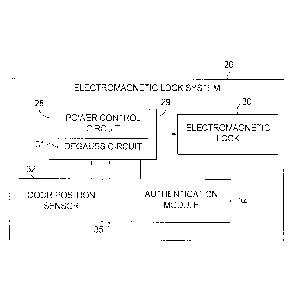
[0011] FIG. 2 is a block diagram illustrating an example electromagnetic
lock
system incorporating the degaussing circuit of the present invention;
[0012] FIG. 3 is a schematic diagram illustrating an example degauss
circuit
suitable for use with an electromagnetic lock system;
[0013] FIG. 4 is a schematic diagram illustrating an equivalent circuit
when
degaussing of the electromagnet coils is active; and
[0014] FIG. 5 is a diagram illustrating the waveforms for the degauss
signal, Q6
gate voltage and the current through the electromagnet coil during both
uncontrolled
and controlled degauss operations.
DETAILED DESCRIPTION
[0015] In the following detailed description, numerous specific details are
set forth
in order to provide a thorough understanding of the invention. It will be
understood by
those skilled in the art, however, that the present invention may be practiced
without
these specific details. In other instances, well-known methods, procedures,
and
components have not been described in detail so as not to obscure the present
invention.
[0016] The subject matter regarded as the invention is particularly pointed
out
and distinctly claimed in the concluding portion of the specification. The
invention,
however, both as to organization and method of operation, together with
objects,
features, and advantages thereof, may best be understood by reference to the
following
detailed description when read with the accompanying drawings.
[0017] It will be appreciated that for simplicity and clarity of
illustration, elements
shown in the figures have not necessarily been drawn to scale. For example,
the
4
CA 2978563 2017-09-08
dimensions of some of the elements may be exaggerated relative to other
elements for
clarity. Further, where considered appropriate, reference numerals may be
repeated
among the figures to indicate corresponding or analogous elements.
[0018] Because the illustrated embodiments of the present invention may for
the
most part, be implemented using electronic components and circuits known to
those
skilled in the art, details will not be explained in any greater extent than
that considered
necessary, for the understanding and appreciation of the underlying concepts
of the
present invention and in order not to obfuscate or distract from the teachings
of the
present invention.
[0019] Any reference in the specification to a method should be applied
mutatis
mutandis to a system capable of executing the method. Any reference in the
specification to a system should be applied mutatis mutandis to a method that
may be
executed by the system.
Definitions
[0020] The following definitions apply throughout this document.
[0021] The term "unauthorized attempt to open the door" shall mean a
forceful
attempt to open the door to gain unauthorized entry to an area secured by the
door.
[0022] The term "naturally occurring external forces" shall mean forces
that may
be applied to the door (e.g., wind forces or vibration) that may move the door
from its
closed position other than forces attributed to an unauthorized attempt to
open the door.
[0023] The term "closed door" position is intended to mean a position of
the door
when it is generally engaged with the door frame or when the armature of the
electromagnet lock is engaged with the electromagnet.
CA 2978563 2017-09-08
Electromagnetic Door Lock
[0024] A diagram illustrating an example electromagnetic door lock
installation
incorporating the degaussing circuit of the present invention is shown in
Figure 1. An
electromagnetic door locking system, generally referenced 10, is shown mounted
to
door frame 16. The locking system comprises electromagnet assembly 18
including
electromagnet 20. Door 12 is provided with an armature 22 for
electromagnetically
locking to electromagnet 20. In a secured setting, an authentication device
24, e.g.,
keypad, swipe card reader, key fob reader or biometric sensor, may be provided
whereby the electromagnet 20 de-energizes only upon input of proper access
credentials at the authentication device, thereby releasing armature 22 from
electromagnet 20.
[0025] The door 12 may optionally be equipped with a mechanical door
release
mechanism 14, such as a push bar, that operates a latch (not shown), the latch
engaging a corresponding recess in door frame 16. Note that alternatively, the
latch
could also be operated by a door knob or door lever. To open door 12 using
door
release mechanism 14, a person pushes on door release mechanism 14 which
causes
the latch to be released from the recess in the door frame, and thereby allow
pushing of
the door outwardly only if the electromagnet is de-energized as described
above.
[0026] A block diagram illustrating an example electromagnetic lock system
incorporating the degaussing circuit of the present invention is shown in
Figure 2. The
electromagnetic door locking system, generally referenced 26, comprises a
power
control circuit 28 including a microprocessor 29 and a degauss circuit 31, an
electromagnetic lock 30 (such as electromagnet 20 and armature 22, Figure 1),
a door
6
CA 2978563 2017-09-08
, =
position sensor 32 installed on the door side or alternatively door position
sensor 33
installed on the door frame side, and an authentication module 34 (such as
authentication device 24, Figure 1).
[0027] Door position sensor 32, 33 may incorporate any suitable
sensor system
capable of sensing when the door is closed and not closed. Example sensor
types
include a photo sensor, a pressure sensor, a micro switch, a passive infrared
sensor, a
radio frequency (RF) sensor or a reed switch, or the like. A "closed door"
position is
understood to mean a position of the door when it is generally engaged with
the door
frame or when the armature of the electromagnet lock is engaged with the
electromagnet. Therefore, door position sensor 32, 33 may also be a magnetic
bond
sensor that monitors when an electromagnetic lock armature is seated against
the
electromagnet, of the type disclosed in U.S. Patent No. 8,094,017.
[0028] Door position sensor 32. 33, may also comprise a
magnetic bond sensor
that senses a change in the magnetic field as the armature separates from the
electromagnet as disclosed in U.S. Patent Publication No. 2010/0325967.
[0029] Note that one or more secondary door position sensors 35
may be
included to work as redundant door position sensors should primary door
position
sensor 32, 33 fail to perform as intended. For example, circuitry may be
provided so
that, if a secondary back-up sensor senses the door to be closed while the
primary
sensor 32, 33 does not, an alert signal may be sent back to power control
circuit 28, and
an alarm signal may be triggered to notify of a malfunctioning primary door
position
7
CA 2978563 2020-01-21
,
sensor 32, 33. A similar alarm signal may be triggered if primary sensor 32,
33 senses
a door closed status and the secondary back-up door position sensor does not.
[0030] Electromagnetic lock 30 is electrically coupled to power
control circuit 28
and is configured to receive electric power from power control circuit 28 so
as to
energize electromagnet 20 and secure door 12 within frame 16 via the
electromagnetic
attraction between electromagnet 20 and armature 22. In one embodiment, when
door
position sensor 32, 33 senses that the door is not closed, electrical power
may be cut
off or reduced to electromagnet 20.
Constant Current Driven Electromagnet
[0031] The door lock system disclosed herein comprises a
constant
current controller that supplies a constant current to an inductive load as
disclosed in U.S. Patent Application No. 15/098,522. The inductive
load comprises an inductance (L) and series resistance (R).
The controller comprises a switching circuit incorporating a primary switch
and a
secondary switch. During a time interval in which the primary switch is closed
(tõ), the
secondary switch is open and the voltage across the inductive load is equal to
the
source voltage (V.). At time ton until the end of a time period (T), with the
primary switch
open and the secondary switch closed, zero volts appears across the inductive
load.
During this interval, load current continues to flow due to the stored energy
in the
inductance. The periodic current in the inductive load is dependent upon the
stored
energy, the parameters of the control circuit, and the duration of
[0032] In one embodiment, the controller further operates as a
pulse width
modulation (PWM) controller that causes the periodic current in the inductive
load to
8
CA 2978563 2020-01-21
become constant by implementing a sufficiently large switching frequency. As
the
frequency increases, the boundary current and the peak current approach the
same
constant value. In one embodiment of the controller, the inductive load may
comprise a
solenoid, DC motor, or a magnetic actuator. In one embodiment of the
controller, the
primary switch comprises a MOSFET and the secondary switch may comprise a
freewheeling diode. In one embodiment, the inductive load may be used to lock
and
unlock an electromechanical door latch or electromechanical strike.
[0033] In one embodiment of the controller, the switching circuit may
comprise a
current transformer, bridge rectifier, burden resistor, and low-pass filter.
In this
embodiment, the current transformer has two single-turn primary windings and
one
secondary winding. The first primary winding is connected in series with the
primary
switch. The second primary winding is connected in series with the secondary
switch
and the primary windings are used for sensing the current of the inductive
load. The
secondary winding has N-turns and is directly connected to the AC input of the
bridge
rectifier. The burden resistor is connected directly across the DC output of
the bridge
rectifier. The burden resistor is directly connected to the low-pass filter.
[0034] In another embodiment, the switching circuit may comprise a current
transformer, bridge rectifier, burden resistor, low-pass filter, and a timer
integrated
circuit (TIC). In this embodiment, the current transformer has two single-turn
primary
windings and one secondary winding. The first primary winding is connected in
series
with the primary switch and the second primary winding is connected in series
with the
secondary switch. The primary windings are used for sensing the current of the
inductive load. The secondary winding has N-turns and is directly connected to
the AC
9
CA 2978563 2017-09-08
input of the bridge rectifier. The burden resistor is directly connected to
the DC output
of the bridge rectifier. The burden resistor is directly connected to the low-
pass filter.
The TIC establishes the time interval of the periodic current in the inductive
load. To
function in this manner, the TIC receives a signal through an input that
initiates this time
interval.
[0035] In another embodiment, the switching circuit may comprise a current-
sensing circuit and a PWM controller. The primary switch comprises a
transistor, e.g., a
MOSFET, and the secondary switch comprises a diode or MOSFET. The current
sensing circuit may be a current-sense resistor with an amplifier, a current-
sensing
integrated circuit, a Hall-effect current sensor, or any other appropriate
current sensing
circuit known in the art. The current-sensing circuit feeds a voltage
proportional to load
current to the PWM controller which correspondingly adjusts the duty ratio to
achieve
the desired load current.
[0036] In another exemplary circuit implementation of the constant-current
controller, the PWM controller controls the duty ratio of the primary switch.
The PWM
controller may be a software-programmable device such as a microprocessor or a
firmware programmable device such as a microcontroller or FPGA. The PWM
controller
may also contain the necessary circuitry to drive the primary switch. The
primary switch
may be a MOSFET or other appropriate switching device. A secondary switch may
be a
diode or other appropriate switching device. A current-sensing circuit
provides a voltage
proportional to load current to the PWM controller which adjusts the duty
ratio to
achieve the desired load current. The current-sensing circuit may be a current-
sense
CA 2978563 2017-09-08
resistor, a current-sense amplifier, a Hall-effect sensor, or other suitable
current sensing
circuit.
[0037] In this embodiment, the current-sensing circuit measures the current
through the inductive load when the primary switch is on and the secondary
switch is
off. When the primary switch is off, current continues to flow through the
secondary
switch during which the time current-sensing circuit continues to measure the
current of
the inductive load.
[0038] In another exemplary circuit implementation of the constant-current
controller, the PWM controller controls the frequency and/or the duty ratios
of the
primary switch and secondary switch. The PWM controller may be a software
programmable device such as a microprocessor or a firmware programmable device
such as a microcontroller or FPGA. The PWM controller may also contain the
necessary
circuitry to drive the primary switch and secondary switch. The primary switch
may be a
MOSFET or other appropriate switching device; the secondary switch may also be
a
MOSFET or other appropriate switching device. The current-sensing circuit
provides a
voltage proportional to load current to the PWM controller which adjusts the
PWM
frequency and/or duty ratio to achieve the desired load current. The current-
sensing
circuit may be a current-sense resistor, a current-sense amplifier, a Hall-
effect sensor,
or other suitable current sensing circuit.
[0039] In this embodiment, the current-sensing circuit measures the current
of the
inductive load when the primary switch is on and the secondary switch is off.
When the
primary switch is off, the secondary switch is on and current continues to
flow through
the inductive load and the current-sensing circuit. When the secondary switch
is on and
11
CA 2978563 2017-09-08
the primary switch is off, the current-sensing circuit continues to measure
the current of
the inductive load. The PWM controller generates the appropriate signals to
synchronously alternate the on-times and off-times of the primary and
secondary
switches, respectively.
Degauss Circuit Operation
[0040] The electromagnetic lock operates by passing current though coils
that
surround a ferrous core. This generates a magnetic field that permeates the
core
creating a magnetic holding force. When the current is removed the magnetic
field
collapses but the core material maintains some residual magnetism that
continues to
attract the strike plate. This residual magnetism must be neutralized using a
degauss
circuit which generates an opposing magnetic field by reversing the direction
of the
current flowing through the coil.
[0041] In one exemplary embodiment known in the art, degaussing is
accomplished using double pole double throw (DPDT) relay. When the relay is in
a
normally closed (NC) state, current flows through the windings in one
direction and
when activated, the current flows through the normally open (NO) contact
state. The
timing of when to trip the relay and for how long, however, is critical in
that if current
flows in the opposite direction for too long then a magnetic field will be
generated in the
opposite direction leaving yet another residual field to neutralize.
[0042] In a second exemplary embodiment known in the art, degaussing is
achieved by generating an opposing field such that when power is removed from
the
electromagnet, an underdamped current response (ringing) is introduced via a
capacitive/resistive circuit. As the ringing dissipates, it has induced the
required
12
CA 2978563 2017-09-08
opposing current to negate the magnetic field. This method, however, requires
tuning of
the capacitive/resistive circuit in relation to the inductive characteristics
of the
electromagnet.
[0043] In the first and second exemplary embodiments described supra, a key
aspect is the use of a constant applied voltage while the electromagnet is
engaged. In
the second embodiment, the capacitor in the circuit is charged to the applied
voltage
when engaged, acting like a battery. When the applied voltage is removed, the
capacitor discharges its stored energy in an opposing direction thereby
inducing the
ringing which causes the magnetic field to collapse.
[0044] A schematic diagram illustrating an example degauss circuit suitable
for
use with an electromagnetic lock system in accordance with the invention is
shown in
Figure 3. The degauss circuit, generally referenced 40, comprises DC source
42,
Schottky diodes D2, D3, 05, Zener diode D1, transistors Q1, 03, 06, capacitors
C3,
04, 05, 06, C11, resisters R3, R12, R16, R17, R18, R19, driver circuits 44,
56, and
processor 46.
[0045] Under normal operation, such as when a door lock is secure and the
electromagnet is energized, the DC supply 42 provides current that flows
through p-
channel FET 03, the coil and n-channel FET 06. A constant current is
maintained
through the coil by applying a pulse width modulated (PWM) signal 50 generated
by the
processor 46 to driver 56 through R16. The output of the driver is coupled to
the gate of
06 via R18. The current flowing through the coil is sensed via current sense
circuit 54
and input to the processor. The processor implements a software feedback loop
and
generates the PWM signal at an appropriate frequency and/or duty cycle to
maintain a
13
CA 2978563 2017-09-08
desired current flow through the coil resulting in a steady holding force by
the door lock
on the door.
[0046] In one embodiment, the nominal frequency of the PWM signal is
approximately 23 kHz. Note that the processor 46 may be a software-
programmable
device such as a personal computer, hand-held or laptop devices,
multiprocessor
systems, microprocessor, microcontroller or microcomputer based system,
programmable consumer electronics, ASIC or FPGA core, DSP core, minicomputer,
distributed computing environments that include any of the above systems or
devices,
and the like.
[0047] Therefore, a constant current flow through the coil when the
electromagnet is energized is accomplished by turning the gating transistor 06
on and
off via the PWM signal 50. When 06 is on, the current flows through D3, 03,
the coil
and 06. When 06 is off, current flows from C3 through the coil and returns via
D2. It is
noted that the PWM signal controls the state of transistor 06. It is also
noted that the
degauss signal 48 is held in a low state (sinking current from the gate of 03)
when the
degauss circuit is not active which turns p-channel FET 03 on, effectively
shorting
capacitor C3, thereby removing it from the current path.
[0048] Thus, the operation of the electromagnetic lock is not dependent on
a
fixed applied voltage (e.g., the industry standard of 12V or 24V). The circuit
40 is able to
operate across all voltage ranges, allowing it to maintain a constant current
regardless
of supplied voltage level. In one embodiment, the degauss circuit uses this
constant
current feature to its advantage.
14
CA 2978563 2017-09-08
[0049] In a door secure mode, the capacitor C3 is bypassed via switch 03
and
holding force current flows through switch 03 to the coil. During the
degaussing
operation, the switch 03 turns on (i.e. closes) and capacitor C3 is placed in
the circuit
(i.e. in series with the coil inductance).
[0050] The degauss circuit 40 also comprises an inrush circuit comprising
R3,
R5, C5, C11, and 01. In operation, at circuit startup before the five-volt
supply is
established, capacitor C5 charges to the DC supply level minus the voltage
drop across
D3. Once the five-volt supply is established, 01 turns on and shorts out
resistor R5.
[0051] In one embodiment, the degauss circuit is activated every time the
door is
opened. This is to minimize the residual magnetism retained by the
electromagnetic
coil. The degauss circuit can be activated in either one of two modes. The
first is an
uncontrolled degauss and the second is a controlled degauss. Each will be
described in
more detail infra.
[0052] It is noted that the capacitor C3 that provides the degauss ringing
in
combination with the coil inductance, is in series (i.e. in-line) with the
current that flows
through the coil. In addition, it is noted that 03 and 06 play a dual role in
the circuit 40
since they (1) function in energizing the coil to provide secure holding
force; and (2)
function in degaussing the coil in either uncontrolled or controlled operation
modes.
[0053] An uncontrolled degauss occurs when the main source power is removed
from the circuit for whatever reason, e.g., power is suddenly cut, utility
power failure or
blackout, backup power system failure, malicious sabotage, etc. The
uncontrolled
degauss is the typical scenario used when an access control system (ACS)
coupled to
the degauss circuit 40 removes power to allow access through a normally secure
door.
CA 2978563 2017-09-08
An intelligent system would have no warning of this event, therefore immediate
activation of the degauss circuit is required.
[0054] A controlled degauss can occur when an intelligent system has
secondary
functions that allow it to release the door without involving the access
control system. In
this case, the main source power remains on but access is still granted.
Uncontrolled Degaussing
[0055] In an uncontrolled degauss, such as when power is abruptly removed
from
the lock, the DC supply 42 is removed along with the degauss signal 48 and PWM
signal 50. The gate of 03 is pulled high via charge from 05 through R17 which
causes
03 to turn off thereby removing the short across capacitor C3 and placing
C3/C5 in
series with the coil inductance. It is the resonance of this series LC that
provides the
ringing that is used to degauss the coil.
[0056] In addition, the PWM signal 50 is removed which removes the output
from
driver 56. The charge on capacitor C6, charged through D5 via the five-volt
supply, is
applied to the gate of 06 via voltage divider R19/R12 to maintain n-channel
FET 06 in
the on state thereby grounding the coil and D2.
[0057] A schematic diagram illustrating an equivalent circuit when
degaussing of
the electromagnet coils is active is shown in Figure 4. When the DC source in
circuit 40
is removed, the equivalent circuit, generally referenced 60, comprises 05, 03,
D2, R5,
RcOlL, and LCOIL. With the DC source 42 removed, the PWM driving 06 is removed
and
06 is left in its on state. Degaussing is initiated with 03 turned off thus
placing capacitor
03 in the circuit. The RLC combination of RCOIL, LCOIL, and 03/C5 resonate
(i.e. ring,
oscillate, etc.) causing current to reverse direction through the coil thereby
providing
16
CA 2978563 2017-09-08
degaussing. Using this equivalent circuit, when degaussing is required, a
ringing or
oscillation occurs which provides the needed energy to reverse the current in
the coil.
[0058] Note that 01, normally kept on via current from the five-volt supply
through R3, turns off once the five-volt supply is removed. This action may or
may not
be simultaneous with the removal of the DC supply 42. When 01 turns off, 20
Ohm
resistor R5 is placed in the circuit in series with capacitor 05.
[0059] Using the equation
R = (1)
as a guideline, R = R5 + RcoiL, C = C3, the damping of the ringing can be
tuned to
ensure sufficient current reversal to suppress the magnetic field in the lock.
Controlled Degaussing
[0060] In a controlled degauss, the processor sets the degauss signal 48
applied
to the gate of 03 to a high level via driver 44. The gate of 03 is thus pulled
high which
causes 03 to turn off thereby removing the short across capacitor 03 and
placing
03/C5 in series with the coil inductance as in the uncontrolled degauss
operation
described supra. The DC supply 42 is not removed but the processor sets the
PWM
signal 50 high leaving 06 in the on state thereby grounding the coil and D2.
As before, it
is the resonance of the series LC that provides the ringing that is used to
degauss the
coil.
[0061] The schematic diagram illustrating an equivalent circuit when
degaussing
of the electromagnet coils is active shown in Figure 4 is applicable in the
controlled
degauss case with the exception of 20 Ohm resistor R5 which is normally
shorted via
01 remaining on. 01 remains on since the five-volt supply remains which is
connected
17
CA 2978563 2017-09-08
to the base of 01 via R3. Thus, when a controlled degauss operation occurs,
the
equivalent circuit comprises C5 coupled to ground, 03, D2, RcoiL, and LCOIL.
Degaussing occurs with 03 turned off thus placing capacitor C3 in the circuit.
The LC
combination of C3/05 and LCOIL resonate (i.e. ring, oscillate, etc.) causing
current to
reverse direction through the coil thereby providing degaussing. With this
equivalent
circuit, when degaussing is required, a ringing or oscillation occurs which
provides the
needed energy to reverse the current in the coil.
Degauss Waveforms
[0062] A diagram illustrating the waveforms for the degauss signal, 06 gate
voltage and the current through the electromagnet coil during both
uncontrolled and
controlled degauss operations is shown in Figure 5. The waveforms shown in
Figure 5
are results of simulations and depict what transpires during the degaussing of
the
electromagnet. A first portion 76 shows the waveforms during an uncontrolled
degauss
and a second portion 78 shows the waveforms during a controlled degauss. It is
noted
that the time scale represented in the waveforms are with regard to simulation
parameters and are set to aid the simulation and should not be construed as
absolute
representations of the operation of the degauss described. It is appreciated
that
alternative values will provide similar results with different timings.
[0063] With reference to the waveforms during an uncontrolled degauss 76,
at
approximately 20 ms the power is removed from the circuit 40. Although the
degauss
signal 70 is undefined, Q3 is turns off via charge stored on capacitor C5
through resistor
R17. This initiates the ringing sequence. The 06 gate voltage 72 is held high
via the
combination of 06, R19, and R12. Transistor Q6 is kept on long enough after
losing the
18
CA 2978563 2017-09-08
PWM signal 50 to allow the ringing to transition to a reverse current and
return to zero
current (coil current waveform 74), effectively degaussing the electromagnet
(i.e. the
horizontal line indicating zero current through the coil beginning at
approximately 30
ms).
[0064] With reference to the waveforms during a controlled degauss 78, at
approximately 70 ms the degauss signal 70 is set active (i.e. high) which
turns Q3 off.
This initiates the ringing sequence. The 06 gate voltage 72 is held high
either via the
PWM signal 50 set high by the processor or via the combination of 06, R19, and
R12.
In either case, transistor 06 is kept on long enough to allow the ringing to
transition to a
reverse current and return to zero current (coil current waveform 74),
effectively
degaussing the electromagnet (i.e. the horizontal line indicating zero current
through the
coil beginning at approximately 83 ms).
[0065] Those skilled in the art will recognize that the boundaries between
logic
and circuit blocks are merely illustrative and that alternative embodiments
may merge
logic blocks or circuit elements or impose an alternate decomposition of
functionality
upon various logic blocks or circuit elements. Thus, it is to be understood
that the
architectures depicted herein are merely exemplary, and that in fact many
other
architectures may be implemented which achieve the same functionality.
[0066] Any arrangement of components to achieve the same functionality is
effectively "associated" such that the desired functionality is achieved.
Hence, any two
components herein combined to achieve a particular functionality may be seen
as
"associated with" each other such that the desired functionality is achieved,
irrespective
of architectures or intermediary components. Likewise, any two components so
19
CA 2978563 2017-09-08
associated can also be viewed as being "operably connected," or "operably
coupled," to
each other to achieve the desired functionality.
[0067] Furthermore, those skilled in the art will recognize that boundaries
between the above described operations merely illustrative. The multiple
operations
may be combined into a single operation, a single operation may be distributed
in
additional operations and operations may be executed at least partially
overlapping in
time. Moreover, alternative embodiments may include multiple instances of a
particular
operation, and the order of operations may be altered in various other
embodiments.
[0068] The terminology used herein is for the purpose of describing
particular
embodiments only and is not intended to be limiting of the invention. As used
herein, the
singular forms "a", "an" and "the" are intended to include the plural forms as
well, unless
the context clearly indicates otherwise. It will be further understood that
the terms
"comprises" and/or "comprising," when used in this specification, specify the
presence
of stated features, integers, steps, operations, elements, and/or components,
but do not
preclude the presence or addition of one or more other features, integers,
steps,
operations, elements, components, and/or groups thereof.
[0069] In the claims, any reference signs placed between parentheses shall
not
be construed as limiting the claim. The use of introductory phrases such as
"at least
one" and "one or more" in the claims should not be construed to imply that the
introduction of another claim element by the indefinite articles "a" or "an"
limits any
particular claim containing such introduced claim element to inventions
containing only
one such element, even when the same claim includes the introductory phrases
"one or
more" or "at least one" and indefinite articles such as "a" or "an." The same
holds true
CA 2978563 2017-09-08
for the use of definite articles. Unless stated otherwise, terms such as
"first,' "second,"
etc. are used to arbitrarily distinguish between the elements such terms
describe. Thus,
these terms are not necessarily intended to indicate temporal or other
prioritization of
such elements. The mere fact that certain measures are recited in mutually
different
claims does not indicate that a combination of these measures cannot be used
to
advantage.
[0070] The
corresponding structures, materials, acts, and equivalents of all
means or step plus function elements in the claims below are intended to
include any
structure, material, or act for performing the function in combination with
other claimed
elements as specifically claimed. The description of the present invention has
been
presented for purposes of illustration and description, but is not intended to
be
exhaustive or limited to the invention in the form disclosed. As numerous
modifications
and changes will readily occur to those skilled in the art, it is intended
that the invention
not be limited to the limited number of embodiments described herein.
Accordingly, it
will be appreciated that all suitable variations, modifications and
equivalents may be
resorted to, falling within the spirit and scope of the present invention. The
embodiments
were chosen and described in order to best explain the principles of the
invention and
the practical application, and to enable others of ordinary skill in the art
to understand
the invention for various embodiments with various modifications as are suited
to the
particular use contemplated.
21
CA 2978563 2017-09-08