Note: Descriptions are shown in the official language in which they were submitted.
VACUUM ASSISTED SKIN PENETRATING APPLIANCE WITH EXTERNAL
INTERFACE
[0001]
FIELD OF THE INVENTION
[0002] The present invention in general relates to medical devices and
systems and in
particular to percutaneous access devices for preventing infection at the site
of cutaneous access.
More specifically, the invention provides processes and devices for preventing
internalization of
bacteria, other infectious agents, or other unwanted materials from entering
the access point for a
catheter, Steinman pin, Kirschner wires, or other percutaneous instruments.
BACKGROUND OF THE INVENTION
[0003] A common problem associated with implantation of a cutaneous access
device
(PAD) or other skin penetrating appliance is skin regeneration about the
periphery of the
appliance to form an immunoprotective seal against infection. New cell growth
and maintenance
is typically frustrated by the considerable mechanical forces exerted on the
interfacial layer of
cells. In order to facilitate skin regeneration about the exterior of the
appliance, subject cells are
often harvested and grown in culture onto appliance surfaces for several days
prior to
implantation in order to allow an interfacial cell layer to colonize appliance
surfaces in advance
of implantation. Unfortunately, cell culturing has met with limited acceptance
owing to the need
for a cell harvesting surgical procedure preceding the implantation procedure.
Additionally,
maintaining tissue culture integrity is also a complex and time-consuming
task.
[0004] A related context in which cell growth is needed is wound healing,
with DACRON
based random felt meshes have been used to promote cell regrowth in the
vicinity of a wound,
such felts have uncontrolled pore sizes that harbor bacterial growth pockets.
[0005] U.S. Patent 7,704,225 to Kantrowitz solves many of these
aforementioned problems
by providing cell channeling contours, porous biodegradable polymers and the
application of
vacuum to promote cellular growth towards the surface the neck of a PAD. The
facilitating of
1
CA 2978634 2019-10-04
CA 02978634 2017-09-01
WO 2016/141291 PCMJS2016/020895
rapid cellular colonization of a PAD neck allows the subject to act as their
own cell culture
facility and as such affords more rapid stabilization of the PAD, and lower
incidence of
separation and infection.
[0006] FIG. 1 depicts a PAD generally at 100 as shown in U.S. Application
No. 13/416546
to Kantrowitz. A cap 102 is formed of a material such as silicone, a polymer
or a metal and
serves to keep debris from entering the device 100. Preferably, the cap 102 is
remote from the
surface of the epidermis E. The medical appliance 34 depicted as a catheter
and vacuum or
hydrodynamic draw tubing 104 pass through complementary openings 106 and 108,
respectively
formed in the cap 102. The tubing 104 provides fluid communication between a
vacuum or
hydrodynamic draw source 22 and an inner sleeve 12d. The inner sleeve 12d is
characterized by
a large and rigid pore matrix 18 in fluid communication to a vacuum source 22
such that the
source 22 draws (arrow 22D) tissue fluid and fibroblasts 21 into the sleeve
12d. Sleeve 12d has
a surface 24 that is optionally nanotextured to promote fibroblast adhesion.
The surface 24 is
optionally decorated with a pattern of contoured cell-conveying channels. It
is appreciated that
inner sleeve 12d optionally includes matrix 26 thereover, a coating substance
27, or a
combination thereof The coating 27 is appreciated to need not cover the entire
surface 24. The
tissue contacting surface 29 of substance 27 is optionally nanotextured. A
flange 112 is provided
to stabilize the implanted device 100 within the subcuteanous layer S. A
flange 112 is
constructed from materials and formed by methods conventional to the art. For
example, those
detailed in U.S. Patents 4,634,422; 4,668,222; 5,059,186; 5,120,313;
5,250,025; 5,814,058;
5,997,524; and 6,503,228.
[0007] While there have been many advances in skin penetrating appliance
designs for
preventing infection at the site of skin access, there continues to be a need
for improved external
interfaces for implanted appliances.
SUMMARY OF THE INVENTION
[0008] A modular external interface includes a main body with an aperture
configured to
form a collar seal about an external neck portion of a skin penetrating
appliance. The modular
external interface has a portal configured for insertion of a vacuum tube, and
at least one
driveline inserted through the aperture and into the appliance.
2
CA 02978634 2017-09-01
WO 2016/141291 PCT/US2016/020895
[0009] A modular external interface includes a main body with an aperture
configured to
form a collar seal about an external neck portion of a skin penetrating
appliance, where a slit
extends outward from the aperture. A portal configured for insertion of a
vacuum tube is on the
main body, where the portal is in fluid communication with a vacuum channel on
a bottom side
of the main body. A foam layer is positioned under the main body, and at least
one driveline
inserted through the aperture and into the appliance.
[0010] A process of using the modular external interface to form a collar
seal about an
external neck portion of a skin penetrating appliance is provided that
includes placing the
modular external interface over the external neck portion of the skin
penetrating appliance
implanted in a subject, and applying a medical dressing to secure the modular
external interface
to the patient's skin.
BRIEF DESCRIPTION OF THE DRAWINGS
[0011] The subject matter that is regarded as the invention is particularly
pointed out and
distinctly claimed in the claims at the conclusion of the specification. The
foregoing and other
objects, features, and advantages of the invention are apparent from the
following detailed
description taken in conjunction with the accompanying drawings in which:
[0012] FIG. 1 is a prior art, partial cutaway view of a flanged
percutaneous access device
(PAD) with relative dimensions of aspect exaggerated for visual clarity;
100131 FIGs. 2A-2C are perspective views of a modular external interface
seal for a PAD
appliance in accordance with an embodiment of the invention;
[0014] FIG. 3 illustrates a side cross sectional view of FIG. 2C according
to an embodiment
of the invention;
[0015] FIG. 4 is an exploded view of the modular external interface for a
percutaneous
access device according to an embodiment of the invention;
[0016] FIG. 5 illustrates the modular external interface attached to a
patient with an
underlying PAD in accordance with an embodiment of the invention;
[0017] FIGs. 6A and 6B are perspective views of a modular external
interface seal for a
PAD appliance in accordance with an embodiment of the invention;
[0018] FIG. 7A is a perspective view of a modular external interface with a
star or spoke
foam insert;
3
CA 02978634 2017-09-01
WO 2016/141291 PCT/US2016/020895
[0019] FIG. 7B is a cross-sectioned view of FIG. 7A in accordance with an
embodiment of
the invention,
[0020] FIGs. 8A and 8B illustrate a simple split in the main body in
accordance with
embodiments of the invention;
100211 FIGs. 9A and 9B illustrate a slanted slit in accordance with
embodiments of the
invention;
[0022] FIGs. 10A and 10B are perspective views of a modular external
interface seal with a
locking feature in accordance with an embodiment of the invention,
[0023] FIGs 11A and 11B are a comparison of the modular external interface
as shown in
FIG. 2A and 6A in accordance with an embodiment of the invention;
[0024] FIGs. 12A and 12B are perspective views of a support foam insert for
use with a
modular external interface seal in accordance with an embodiment of the
invention;
[0025] FIGs. 13A-13C are perspective views of the main body portion of a
modular external
interface seal in accordance with an embodiment of the invention;
[0026] FIG. 14 is a perspective view of a modular external interface seal
in accordance with
an embodiment of the invention, and
[0027] FIG. 15 is a perspective view of a modular external interface seal
joined about a
skin-appliance interface in accordance with an embodiment of the invention.
[0028] The detailed description explains the preferred embodiments of the
invention.
DESCRIPTION OF THE INVENTION
[0029] The present invention has utility as a system and method for a
modular external
interface for a skin penetrating appliance. The present invention also
provides processes and
devices for preventing internalization of bacteria, other infectious agents,
or other unwanted
materials from entering the access point for a catheter, Steinman pin,
Kirschner wires, or other
percutaneous instruments.
[0030] While such an appliance is depicted in the accompanying figures as
an embedded
percutaneous access device (PAD), it is appreciated that it is applicable to a
variety of such
appliances including a catheter, a Steinman pin, and a Kirschner wire
Embodiments of the
modular external interface provide for the hermaticity in the vicinity of the
skin-appliance (PAD)
interface with fluid exudate or transudate egressing from the vicinity of the
skin-PAD interface.
4
CA 02978634 2017-09-01
WO 2016/141291 PCT/US2016/020895
Embodiments of the modular external interface form a hermetic seal with the
external neck of an
implanted PAD with a locking feature that joins the main body of the modular
external interface
together around the neck of the PAD. Embodiments of the modular external
interface provide
additional mechanical stability to an implanted PAD so as to speed healing
around a semi-
permanent implanted PAD, as well as connection points for vacuum lines and at
least one drive
line for the insertion of medical devices.
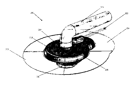
100311 Referring now to the figures, FIGs. 2A-2C illustrate an embodiment
of an inventive
modular external interface housing 200 coupled to a PAD 100. The modular
external interface
200 forms a collar about the neck 110 of the PAD 100 with the main body 216
with a locking
feature 218, such as a male extension that engages a female receptacle or
cavity as a mechanical
overlap connection. In a specific embodiment the main body 216 is made of
silicone. As best
shown in FIG. 3, the collar seal between the main body 216 and the neck 110 of
the PAD 100
forms a hermetic seal with a gasket 230, which in a specific embodiment is a
flexible gasket
integrated into the main body 216. In a specific embodiment the gasket 230 may
be a floating
gasket The stabilization of the PAD 100 within the skin to form a germ-free
barrier requires
subject cells to grow onto the neck surfaces 16 of the PAD 100 adjacent to the
subject's
epidermis E. The neck surface region 16 is adapted to promote growth of
autologous fibroblast
cells thereon. A suitable exterior side surface substrate for fibroblast
growth is a nanotextured
polycarbonate (LEXANR).
100321 The modular external interface 200 is secured and sealed to an outer
layer of a
patient's skin with a medical dressing. In a specific embodiment the medical
dressing is a
preform patterned and shaped to conform to the exterior of the modular
external interface 200.
In a specific embodiment the medical dressing preform may be in two halves
(212 214) that
overlap. In a specific embodiment the medical dressing preform may be
transparent. In a
specific embodiment the medical dressing preform may be made of TegadermTm
manufactured
by Minnesota Mining and Manufacturing Company.
100331 The modular external interface 200 has a central opening adapted at
least one drive
line 220 for insertion into a PAD, and a portal 224 for a vacuum line 222. As
best shown in
FIGs. 3 and 4 a skin protection layer 228 and a foam disc 226 are positioned
in the interior of the
modular external interface 200. FIG 5 illustrates the modular external
interface attached to a
patient with an underlying PAD in accordance with an embodiment of the
invention.
CA 02978634 2017-09-01
WO 2016/141291 PCT/US2016/020895
[0034] FIG. 6A is an inventive embodiment of a modular external interface
300 configured
to be coupled to the neck of an access device, where the access devices
illustratively include a
PAD such as the PAD 100 described in FIG. 1. The modular external interface
300 forms a seal
with aperture 330 around a cylindrical neck of an access device, where the
seal is enhanced by
an applied vacuum through vacuum line 222. It should be appreciated that other
geometries
besides a circle for a neck extending from an access device may be
accommodated, illustratively
including a square, rectangle, triangle, or oval. In a specific embodiment the
main body 316 is
made of silicon and is placed over a foam layer 326, and the top outer surface
of the main body
316 may have a layout line to provide guidance for placement of a securing
medical dressing
illustratively including TegadermTm. The medical dressing is placed over the
modular external
interface 300 and attached to the subject's skin. The oval like shape and
tapered sides 332 of the
main body 316, which has no concavities, is configured to prevent wrinkling of
the medical
dressing where the main body 316, foam layer 326, and the subject's skin meet.
The foam layer
326 may extend up to or just past the border of the tapered sides 332 of the
main body 316. The
foam layer 326 compacts and lowers the main body 316 over an implant or access
device neck.
Slit 334 in the main body 316 is provided to fit the modular external
interface 300 around the
neck of the implant or access device.
[0035] As best shown in FIG. 6B, the bottom perspective view with the foam
layer 326 in
transparent relief, a vacuum channel 328 is in fluid communication with vacuum
attachment
portal 324 for the vacuum line 222. The larger foam piece that forms the foam
layer 326 moves
the vacuum line entrance at the attachment portal 324 further away from the
drive line that is
inserted through aperture 330 and into the neck of the access device. In
addition, the vacuum
channel 328 of main body 316 is moved out radially from the neck of the
implant/access device
as compared to the main body 216 of modular external interface 200 as shown in
side by side
comparison in FIGs. 11A and 11B.
[0036] FIG. 7A is an inventive embodiment of a modular external interface
400 configured
to be coupled to the neck of an access device. Main body 416, which may be
made of silicone in
a specific embodiment, has support ribs 436 which support the skin from
prolapsing. A foam
insert 426 has a star shape to accommodate the support ribs 436 The foam
insert in a specific
embodiment may also have a circular circumference to support the subject's
skin from the
vacuum path. The modular external interface 400 forms a seal with aperture 430
around a
6
CA 02978634 2017-09-01
WO 2016/141291 PCT/US2016/020895
cylindrical neck of an access device, where the seal is enhanced by an applied
vacuum through
vacuum line 222. It should be appreciated that other geometries besides a
circle for a neck
extending from an access device may be accommodated, illustratively including
a square,
rectangle, triangle, or oval. The oval like shape and tapered sides 432 of the
main body 416,
which has no concavities, is configured to prevent wrinkling of the medical
dressing where the
main body 416 and the subject's skin meet. FIG. 7B is a cross-sectional view
along line A-A of
FIG. 7A.
100371 FIGs. 8A and 8B illustrate a simple slit 334 for the modular
external interface 300 of
FIG. 6A. In embodiments of the modular external interface 300 with a simple
slit 334, the
securing medical dressing holds the halves of the modular external interface
300 together. In a
specific embodiment, a transfer tape that is designed to adhere to silicone
surfaces may be used
for a stronger and more secure holding of the halves together. FIGs. 9A and 9B
illustrate a
simple slanted slit 336 for the modular external interface 300 of FIG. 6A. The
slant in slit 336
allows for two sides of main body 316' to spread apart and still seal to one
another, where
opposing sides at the slant slit 336 overlap. In a similar manner, the slant
in the slit 336 may
utilize a transfer tape that is designed to adhere to silicone surfaces, and
the tape may be used for
a stronger and more secure holding of the halves joined together with the
slanted slit 336.
[0038] FIGs. 10A and 10B illustrate a modular external interface 300¨ that
forms a collar
about the neck 110 of the PAD 100 with the main body 316- with a locking
feature 338, such as
a male extension that engages a female receptacle or cavity as a mechanical
overlap connection
in a tongue 340 and groove 342 configuration. The puzzle like configuration of
the locking
feature 338 is also formed in the foam layer 326, and keeps the foam 326 and
the main body
from pulling apart.
[0039] FIG. 15 is an inventive embodiment of a modular external interface
500 configured
to be coupled to the neck of an access device, where the access devices
illustratively include a
PAD such as the PAD 100 described in FIG. 1. FIG. 14 illustrates the modular
external interface
500 prior to positioning about the neck of an access device. The modular
external interface 500
forms a seal with aperture 530 around a cylindrical neck 110 of an access
device, where the seal
is enhanced by an applied vacuum through vacuum line 222 attached to the
modular external
interface 500 via vacuum attachment portal 524. It should be appreciated that
other geometries
besides a circle for a neck extending from an access device may be
accommodated, illustratively
7
Docket No.: LT1-129PCT
including a square, rectangle, triangle, or oval. It should be noted that in
FIGs. 13-15 the main
body 516 is shown as transparent, but in other embodiments the main body may
be translucent.
In a specific embodiment the main body 516 is made of silicon and is placed
over a foam layer
526, and the top outer surface of the main body 516 may have a layout line to
provide guidance
for placement of a securing medical dressing illustratively including
Tegadermi-m. The medical
dressing is placed over the modular external interface 500 and attached to the
subject's skin. The
oval like shape and tapered sides or edges 532 of the main body 516, which has
no concavities,
is configured to prevent wrinkling of the medical dressing where the main body
516, foam layer
526, and the subject's skin meet. The foam layer 526 may extend up to or just
past the border of
the tapered sides 532 of the main body 516. The foam layer 526 compacts and
lowers the main
body 516 over an implant or access device neck. Slit 534 in the main body 516
is provided to fit
the modular external interface 500 around the neck of the implant or access
device. FIG. 13B
illustrates the main body 516 with the slit 534 separated for placement around
the neck of the
implant or access device.
[0040] In a specific embodiment, the main body 516 has support ribs which
support the skin
from prolapsing. A support foam insert 527 as shown in FIGs. 12A and 12B has a
rounded shape
with branches or arms 529 protruding radially outward to accommodate the
support ribs. The
protruding arms 529 are configured to be inserted in channels in the main body
516, as best
shown in FIGs. 13A-13C, where excess length of the protruding arms 529 are
trimmed off in
FIG. 13C.
[0041] Patent documents and publications mentioned in the specification
are indicative of
the levels of those skilled in the art to which the invention pertains.
[0042] The foregoing description is illustrative of particular embodiments
of the invention,
but is not meant to be a limitation upon the practice thereof. The following
claims, including all
equivalents thereof, are intended to define the scope of the invention.
8
CA 2978634 2019-10-04