Note: Descriptions are shown in the official language in which they were submitted.
-1-
METHOD AND APPARATUS FOR PROVIDING AMPLIFIED RADIATION
CROSS-REFERENCE TO RELATED APPLICATIONS
[0001] DELETED
BACKGROUND OF THE DISCLOSURE
1, Field of the Disclosure
[0002] The present disclosure relates generally to optical fiber lasers and
amplifiers.
The present disclosure relates more particularly to methods and systems for
providing
optical radiation having improved rise/fall times and improved levels of
leakage
power.
2. Technical Background
[0003] Optical fiber lasers and amplifiers are known in the art. In such
lasers and
amplifiers, rare earth materials disposed in the core of the optical fiber
therein absorb
pump radiation of a predetermined wavelength, and, in response thereto,
generate or
amplify light of a different wavelength for propagation in the core. For
example, the
well-known erbium doped fiber receives pump radiation having a wavelength of
980
or 1480 nm, and generates or amplifies optical radiation propagating in the
core and
having a wavelength of about 1550 nm. Lasers and amplifiers generally include
one
or more amplifier stages, each including a length of fiber that is coupled to
one or
more pump radiation sources (e.g., pump lasers) and configured to amplify
optical
radiation passing through its core.
[0004] Optical radiation can have a rise time, i.e., the time it takes to
reach a
threshold power from substantially no power, and a fall time, i.e., the time
it takes to
Date Recue/Date Received 2022-06-29
CA 02978728 2017-09-05
WO 2016/141290 -2-
PCT/US2016/020891
drop below a threshold power from a substantially high power. Fast rise and
fall
times are desirable in many real-world applications of optical fiber lasers
and
amplifiers. Conventional high-power laser systems include multiple
amplification
stages, arranged in series. An example of a conventional high-power laser
system 100
is shown in schematic view in FIG. 1. The laser system includes three
amplification
stages (110, 130), arranged in series with optical fibers connecting the
output of one
amplification stage to the input of the next; a seed laser 105 is included to
provide
initial radiation to the first amplifier stage in the chain. Each
amplification stage
includes an active optical fiber (112, 132). One or more pump diodes (115,
135) are
configured to pump the various active optical fibers of the amplifier stages.
Typically, the bulk of the amplifier power is provided by the final amplifier
stage.
The pump diodes of each stage need to be switched on or off when the output
state of
the laser system is to be changed. The switching of the pump diodes of the
various
amplification stages need to be coordinated in order to turn the overall
system into an
on or off state. A controller configured to switch the pump diodes on and off
in a
coordinated fashion is indicated by reference numeral 140. But precisely
coordinating
the switching of the laser diodes of different amplification stages is
difficult; such
difficulties tend to limit the speed of rise and fall of the amplified
radiation output by
the system.
[0005] This problem is conventionally addressed using a "simmer mode" in
which,
during their "off' state, a simmer current less than the lasing threshold
passes through
the pump diodes. This can help to improve the overall rise/fall time of the
system, but
requires complicated algorithms to ensure coordinated switching of the
different
amplification stages to prevent potential damage caused by a lack of signal
power.
CA 02978728 2017-09-05
WO 2016/141290 -3-
PCT/US2016/020891
Moreover, these complicated algorithms are often insufficient to provide the
desired
rise/fall time to the system.
[0006] Another conventional manner in which this problem is addressed is to
switch
on and off only the final pump diode, leaving the pump diodes for the previous
stages
in a high power state. However, this can lead to an unacceptable level of
leakage
power for the overall system when it is in an "off' state.
[0007] Accordingly, there remains a need for improved optical amplifying
systems
and methods that can provide improved amplification rise/fall times.
SUMMARY OF THE DISCLOSURE
[0008] One aspect of the present disclosure is an optical fiber amplifying
system, the
optical fiber amplifying system providing amplified optical radiation having a
first
amplified wavelength, the optical fiber amplifying system comprising
an optical source having an output, the optical source being configured to
provide
radiation of the first amplified wavelength;
an intermediate stage having an input operatively coupled to the output of the
optical source and an output, the intermediate stage comprising an
intermediate active optical fiber having an amplified wavelength that is
substantially the same as the first amplified wavelength and a first pump
wavelength;
a final amplifying stage having an input coupled to the output of the
intermediate
stage and an output, the final amplifying stage comprising a final active
optical fiber, the final active optical fiber being configured to amplify
radiation at the first amplified wavelength when pumped with pump radiation
of the first pump wavelength; and
CA 02978728 2017-09-05
WO 2016/141290 -4-
PCT/US2016/020891
one or more final optical pump sources together operatively coupled to the
final
active optical fiber and the intermediate active optical fiber and configured
to
output radiation of the first pump wavelength.
[0009] Another aspect of the disclosure is a method for amplifying optical
radiation.
The method includes providing an optical fiber amplifying system as described
herein, then providing optical radiation having the first amplified wavelength
from the
optical source to the input of the intermediate active optical fiber, wherein
the one or
more final optical pump sources are together in a low power state such that
the optical
radiation is substantially absorbed by the intermediate active optical fiber
and such
that substantially no optical radiation of the amplified wavelength is
transmitted by
the output of the intermediate stage. The method can further include switching
the
one or more final optical pump sources from the low power state to a high
power
state, such that the optical radiation of the amplified wavelength is
substantially
transmitted by the intermediate active optical fiber and such that substantial
optical
radiation of the amplified wavelength is transmitted by the output of the
intei mediate
stage
[0010] Any of the features described herein in conjunction with any one aspect
or
embodiment described herein can be combined with features described with
respect to
any other of the aspects or embodiment described herein, as would be evident
to the
person of ordinary skill in the art in view of the present disclosure.
BRIEF DESCRIPTION OF THE DRAWINGS
[0011] FIG. 1 is a schematic view of a conventional optical laser system;
[0012] FIG. 2 is a schematic view of an optical fiber amplifying system
according to
one embodiment of the disclosure;
CA 02978728 2017-09-05
WO 2016/141290 -5-
PCT/US2016/020891
[0013] FIG. 3 is a partial schematic view of a laser cavity optical source
useful in
certain aspects of the disclosure;
[0014] FIG. 4 is a partial schematic view of an amplifiying stage useful in
various
aspects of the disclosure;
[0015] FIG. 5 is a schematic view of a final amplifying stage according to
certain
aspects of the disclosure;
[0016] FIG. 6 is a partial schematic view of an optical fiber amplifying
system
according to one embodiment of the disclosure; and
[0017] FIG. 7 is a schematic view of an optical fiber amplifying system
according to
another embodiment of the disclosure.
[0018] As the person of ordinary skill in the art will appreciate, the
drawings are not
necessarily drawn to scale, and various elements of the systems may in certain
drawings be omitted for purposes of clarity.
DETAILED DESCRIPTION
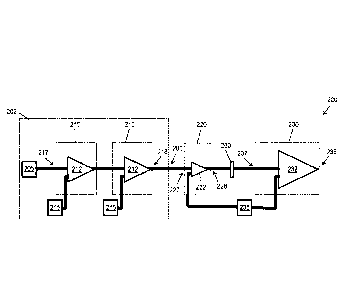
[0019] One embodiment of the disclosure is shown in schematic view in FIG. 2.
Optical amplifying system 200 is configured as a multi-stage fiber laser.
While the
amplifying system 200 of FIG. 2 is configured with four active fiber stages,
the
person of ordinary skill in the art will appreciate that other numbers of
stages could be
used. Optical amplifying system 200 provides amplified optical radiation
having a
first amplified wavelength. As described in more detail below, the person of
ordinary
skill in the art can select combinations of pump wavelengths and active
optical fibers
to provide a variety of amplified wavelengths.
CA 02978728 2017-09-05
WO 2016/141290 -6-
PCT/US2016/020891
[0020] Optical fiber amplifying system 200 of FIG. 2 provides amplified
optical
radiation having a first amplified wavelength. It includes an optical source
202
having an output 203. The optical source 202 is configured to provide
radiation of a
first amplified wavelength. The system 200 further includes an intermediate
stage
220. The intermediate stage 220 has an input 227 operatively coupled to the
output
203 of the optical source 202 and an output 228, and includes an intermediate
active
optical fiber 222. As the person of ordinary skill in the art will appreciate,
an active
optical fiber is an optical fiber that can provide amplified radiation at an
amplified
wavelength upon being pumped with pump radiation of a suitable pump
wavelength.
The intermediate active optical fiber has an amplified wavelength that is
substantially
the same as the first amplified wavelength and a first pump wavelength. As the
person of ordinary skill in the art will appreciate, the pump wavelength of an
active
optical fiber is a wavelength of radiation that will cause the active optical
fiber to
amplify radiation of an amplified wavelength. Here, the first pump wavelength
is a
wavelength that will cause the active optical fiber to amplify radiation of
the first
amplified wavelength.
[0021] The optical amplifying system also includes a final amplifying stage
230. The
final amplifying stage 230 has an input 237 and an output 238, and includes a
final
active optical fiber 232. The final active optical fiber is configured to
amplify
radiation at the first amplified wavelength when pumped with pump radiation of
the
first pump wavelength. One or more final optical pump sources 235 are together
operatively coupled to the final active optical fiber and the intermediate
active optical
fiber.
CA 02978728 2017-09-05
WO 2016/141290 -7-
PCT/US2016/020891
[0022] The optical source 202 can take many forms. In one embodiment, the
optical
source can be a seed optical source such as a seed laser or oscillator. In
certain
embodiments, the optical source includes one or more first amplifying stages
together
having an output, each of the one or more first amplifying stages comprising a
first
active optical fiber, the first active optical fiber being configured to
amplify radiation
at the first amplified wavelength when pumped with pump radiation of a second
pump
wavelength; and one or more first optical pump sources, each configured to
output
radiation of the second pump wavelength, each operatively coupled to one or
more of
the first active optical fibers of the first amplifying stages. In the
embodiment of FIG.
2, the optical source 202 includes two initial amplifying stages 210.
Together, the
first amplifying stages have an input 217 and an output 218. Each of the first
amplifying stages includes an active optical fiber 212. The active optical
fiber(s) of
the first amplifying stage(s) are configured to amplify radiation at the first
amplified
wavelength when pumped with pump radiation of a second pump wavelength. The
second pump wavelength can be, for example, substantially identical to the
first pump
wavelength. Accordingly, the optical fiber amplifying system 200 also includes
one
or more first optical pump sources 215, each configured to output radiation of
the
second pump wavelength, and each operatively coupled to one or more of the
first
active optical fibers of the first amplifying stages. While the optical fiber
amplifying
system of FIG. 2 includes two first amplifying stages, the person of ordinary
skill in
the art will appreciate that any convenient number of first amplifying stages
can be
used. Moreover, in other embodiments, the optical source can simply be a fiber
that
carries radiation from a remote source.
[0023] An optical fiber amplifying system that includes one or more first
amplifying
stages can further include a seed optical source, such as a seed laser or
oscillator,
CA 02978728 2017-09-05
WO 2016/141290 -8-
PCT/US2016/020891
having an output optically coupled to the input of the one or more first
amplifying
stages. For example, optical fiber amplifying system 200 of FIG. 2 includes a
seed
laser 205 having an output optically coupled to the input 217 of the first
amplifying
stages 210. The seed laser or oscillator can provide seed radiation of the
first
amplified wavelength, as would be appreciated by the person of ordinary skill
in the
art. Of course, in other embodiments, no seed optical source is present; the
first
amplifying stages can generate radiation through the amplification of
spontaneous
emission in such cases, as would be apparent to the person of ordinary skill
in the art.
[0024] Another aspect of the disclosure is a method for generating amplified
radiation. The systems described herein can be used in various aspects to
perform the
methods described herein. In one embodiment, a method for amplifying optical
radiation includes providing an optical fiber amplifying system that includes
an
optical source, an intermediate stage, a final amplifying stage and one or
more final
optical pump sources substantially as described herein. Optical radiation
having the
first amplified wavelength is provided to the input of the intermediate stage
while the
one or more final optical pump sources are together in a low power state, such
that the
optical radiation is substantially absorbed by the intermediate active optical
fiber and
such that substantially no optical radiation of the amplified wavelength is
transmitted
by the output of the intermediate stage. In certain embodiments, the method
further
includes switching the one or more final optical pump sources from the low
power
state to a high power state, such that the optical radiation is substantially
transmitted
by the intermediate active optical fiber and such that substantial optical
radiation of
the amplified wavelength is transmitted by the output of the intermediate
stage.
CA 02978728 2017-09-05
WO 2016/141290 -9-
PCT/US2016/020891
[0025] The present inventors have determined that the active optical fiber of
the
intermediate stage can act, in essence, as an optical switch for optical
radiation of the
first amplified wavelength. When the one or more optical pump sources are in a
low
power state, the intermediate active optical fiber can be in a substantially
non-inverted
state (e.g., metallic dopant species are substantially in their ground state).
As such,
the intermediate active optical fiber will absorb radiation of the first
amplified
wavelength instead of amplifying it. The absorbed radiation of the first
amplified
wavelength will be converted to other forms of energy by the intermediate
active
optical fiber, for example, to heat, or to radiation of other wavelengths. For
example,
the absorbed radiation of the first amplified wavelength can be converted to
amplified
spontaneous emission having a wavelength greater than the first amplified
wavelength. As the person of ordinary skill in the art will appreciate, the
wavelength(s) of the amplified spontaneous emission will depend on the details
of the
intermediate active optical fiber and the first amplified wavelength. When the
one or
more final pump sources are in a high power state, however, they can put the
intermediate active optical fiber in a substantially inverted state (e.g.,
with a
substantial fraction of metallic dopant species in an excited state). As the
person of
ordinary skill in the art will appreciate, when the intermediate active
optical fiber is in
a substantially inverted state, it can be substantially transmissive to
optical radiation
of the first amplified wavelength.
[0026] Accordingly, by switching the one or more final optical pump sources
between
a low power state and a high power state, the intermediate stage can be
switched
between substantially non-transmissive (e.g., less than about 5%, less than
about 1%,
or even less than about 0.1% transmissive) and substantially transmissive
(e.g.,
greater than about 800/o, greater than about 90% or even greater than about
99%) to
CA 02978728 2017-09-05
WO 2016/141290 -10-
PCT/US2016/020891
radiation of the first amplified wavelength. The one or more final optical
pump
sources can therefore alone be used to turn on and off the overall system
output, for
example, to carve out pulses of a desired fast rise time and/or fast fall
time. As the
intermediate stage can be switched to be substantially non-transmissive, it is
not
necessary to switch off any earlier stages. Accordingly, the optical source
can remain
at a high power state. For example, when the optical fiber amplifying system
includes
one or more first amplifying stages as described above, the one or more first
optical
pump sources can remain at a high power state, even while the overall system
is not to
be generating power. For example, the optical source can remain at
substantially the
same power throughout the process (i.e., while the one or more final optical
pump
sources are switched between low power and high power states), or at least at
substantially high power throughout the process. Thus, when present, the seed
source
and/or the one or more first optical pump sources can, for example, remain at
substantially same power throughout the process. The overall optical fiber
amplifying
system can thus have low leakage power, even though the optical source
continues to
provide radiation of the first amplified wavelength. Low power states and high
power states for the final pump source(s) can be, for example, defined as a
state
providing sufficient power to provide a desired level of transmission to the
intermediate stage. For example, a low power state can be a power sufficiently
low to
render the intermediate stage substantially non-transmissive (e.g., less than
about
10%, less than about 5%, less than about 1%, or even less than about 0.1%
transmissive) to radiation of the first amplified wavelength. This can be
selected, for
example, by providing an appropriate length of fiber to provide the desired
attenuation in the low power state. Similarly, a high power state can be a
power
sufficiently high to render the intermediate stage substantially transmissive
(e.g.,
CA 02978728 2017-09-05
WO 2016/141290 -11-
PCT/US2016/020891
greater than about 80%, greater than about 90%, greater than about 95%, or
even
greater than about 99%) to radiation of the first amplified wavelength.
[0027] In certain desirable embodiments, the methods described herein include
allowing radiation of the amplified wavelength to be transmitted from the
intermediate stage to the final stage, while substantially preventing
amplified
spontaneous emission from being transmitted from the intermediate stage to the
final
stage. Thus, any amplified spontaneous emission that is generated in the
intermediate
stage when the system is in an "off' state can be prevented from leaking
through the
system as leakage power.
[0028] Thus, in certain desirable embodiments, the optical amplifying system
includes one or more optical filters operatively coupled between the
intermediate
stage and the final amplifying stage. In the system of FIG. 2, an optical
filter is
indicated by reference numeral 260. In certain embodiments, the one or more
optical
filters are configured to substantially pass radiation of the amplified
wavelength from
the intermediate stage to the final amplifying stage, and substantially
prevent radiation
of the pump wavelength from being transmitted from the intermediate stage to
the
final amplifying stage. In certain embodiments, the one or more optical
filters are
configured to substantially pass radiation of the amplified wavelength from
the
intermediate stage to the final amplifying stage, and substantially prevent
radiation of
the amplified spontaneous emission wavelength of the intermediate active
optical
fiber from being transmitted from the intermediate stage to the final
amplifying stage.
As the person of ordinary skill in the art will appreciate, the "amplified
spontaneous
emission wavelength" is the wavelength of emission of the intermediate active
optical
fiber resulting from absorption of radiation of the amplified wavelength. In
certain
CA 02978728 2017-09-05
WO 2016/141290 -12-
PCT/US2016/020891
embodiments, the one or more optical filters are configured to substantially
pass
radiation of the amplified wavelength from the intermediate stage to the final
amplifying stage, and substantially prevent radiation of the amplified
spontaneous
emission wavelength of the intermediate active optical fiber and radiation of
the pump
wavelength from being transmitted from the intermediate stage to the final
amplifying
stage. The optical filters can be formed, for example, using fiber Bragg
gratings,
Fabry-Perot structures, dichroic elements or other structures known to the
person of
ordinary skill in the art.
[0029] In certain embodiments, the one or more optical filters operatively
coupled
between the intermediate stage and the final amplifying stage are configured
to allow
radiation of the amplified wavelength that is guided in an inner core of the
fiber to
pass to the final amplifying stage, but to absorb or scatter radiation that is
unguided or
guided in structures outside the inner core. The amplified spontaneous
radiation
generated by the intermediate stage is substantially unguided, or, at most, is
substantially guided only in the pump cladding of an optical fiber. Thus,
wavelength-
based filtering of the amplified spontaneous emission is not necessary in many
systems. For example, an optical filter sufficient to substantially prevent
amplified
spontaneous emission from being transmitted to the final stage can be
configured as a
section of optical fiber with a roughened cladding or an absorptive material
disposed
on the cladding, such that radiation that is unguided or guided in structures
outside the
inner core is absorbed or scattered out of the optical fiber. Such optical
fibers are
commonly used to remove pump radiation from active optical fibers. The optical
fiber can be, for example, a dual-clad fiber.
CA 02978728 2017-09-05
WO 2016/141290 -13-
PCT/US2016/020891
[0030] In certain embodiments, a length of non-amplifying optical fiber
connects the
intermediate stage and the final amplifying stage. Substantially all of the
amplified
spontaneous emission will be coupled out from such an optical fiber, as it is
not
guided in the inner core thereof. Such an optical fiber can therefore act an
optical
filter sufficient to substantially prevent amplified spontaneous emission from
being
transmitted to the final stage. Here, too, the optical fiber can be a dual-
clad fiber.
[0031] The person of ordinary skill in the art will appreciate that the
optical
amplifying systems described herein can be constructed using conventional
techniques in the art. For example, various filters and monitors can be
included in the
system, and the system can be packaged as is typical for optical fiber
amplifying
systems. The various elements (e.g., the seed optical source, the one or more
first
amplifying stages, the various pump sources, the intermediate stage, and the
final
amplifying stage) can be interconnected, for example, using optical fibers
through
conventional techniques familiar to the person of ordinary skill in the art.
In certain
desirable embodiments, the optical path between the optical source and the one
or
more first amplifying stages, if present, is less than about 100 m, or even
less than
about 20 m, or even less than about 5 m. Similarly, in certain desirable
embodiments,
the optical path between the one or more first amplifying stages, if present,
and the
intermediate stage is less than about 100 m, or even less than about 20 m. In
certain
desirable embodiments, the optical path between the intermediate stage and the
final
amplifying stage is less than about 100 m, or even less than about 20 m, or
even less
than about 5 m.
[0032] The one or more first amplifying stages, the intermediate stage and the
final
amplifying stage can be provided in a variety of architectures, and arranged
in a
CA 02978728 2017-09-05
WO 2016/141290 -14-
PCT/US2016/020891
variety of ways, as would be apparent to the person of ordinary skill in the
art. For
example, the optical source can be configured as a laser cavity, with the
active optical
fiber disposed between two partially reflective optical elements and coupled
to the
respective pump source. For example, a partial schematic view of a laser
cavity
optical source is provided as FIG. 3. Laser cavity optical source 302 has an
output
303, and includes an amplifying optical fiber 306 disposed between partially
reflective elements 304 (here, fiber Bragg gratings). A pump coupler 307
couples an
optical pump source 308 to the amplifying optical fiber. In the embodiment of
FIG. 3,
the pump source is arranged in the so-called "co-pumping" configuration, in
which
the pump radiation is transmitted through the amplifying optical fiber in the
same
direction as the input radiation. Of course, the person of ordinary skill in
the art will
appreciate that the counter-pumping configuration (i.e., with the pump source
coupled
to the output end of the amplifying optical fiber, such that the pump
radiation
propagates in the direction opposite the input-output direction of the stage)
can be
used. In other embodiments, both co- and counter-pumping can be provided, and
more than one pump source can be provided regardless of the pumping scheme.
[0033] Additionally or alternatively, a first amplifying stage, the
inteimediate stage,
and/or the final amplifying stage can be configured as an amplifier stage, in
which
there is no laser cavity formed. One example is shown in partial schematic
view in
FIG. 4. Here, final amplifying stage 430 has an input 437 and an output 438,
with a
final amplifying optical fiber 432 extending therebetween. Pump coupler 431
couples
final optical pump source 435 to the output end of the amplifying optical
fiber (i.e., in
the counter-pumping configuration). Here, too, the amplifier stage can
alternatively
be configured in the co-pumping configuration or the co-/counter-pumping
CA 02978728 2017-09-05
WO 2016/141290 -15-
PCT/US2016/020891
configuration. One or more of the first amplifying stages and/or the
intermediate
stage can also be configured as an amplifier.
[0034] As shown in FIG. 1, the one or more final pump sources are configured
to
provide pump radiation not only to the final amplifying stage, but also to the
intermediate stage. In certain embodiments, a plurality of final pump sources
are
configured to be driven by a common voltage source (i.e., controlled by a
common
switch to switch between low- and high power states). This can simplify the
control
scheme, because driving multiple pumps with a common, singly-switched voltage
source can automatically synchronize the pulses from the pumps. For example,
FIG.
is a schematic view of a final amplifying stage 530 in which there are three
pump
sources 535, all driven by a common voltage source 539. The three pump sources
are
coupled together to the final amplifying optical fiber 532 at coupler 531. Of
course,
in other embodiments, the outputs of the three pump sources 535 are combined
before
being coupled to the final amplifying optical fiber 532.
[0035] The output from the one or more final pump sources can be split in an
appropriate ratio between the intermediate stage and the final amplifying
stage. The
ratio of power coupled between the intermediate stage and the final amplifying
stage
can vary, as would be apparent to the person of ordinary skill in the art in
view of the
present disclosure. For example, the intermediate stage/final amplifying stage
ratio
can be in the range of about 1:50 to about 2:1, or about 1:20 to about 1:1.
The power
can be split in a variety of ways familiar to the person of ordinary skill in
the art, for
example, using optical fiber couplers. For example, the output of each final
pump
source can be split first, and the individual fibers for the final amplifying
stage and for
the intermediate stage can then be separately combined. This configuration is
shown
CA 02978728 2017-09-05
WO 2016/141290 -16-
PCT/US2016/020891
in partial view in FIG. 5. Alternatively, the power from a plurality of final
pump
sources can first be combined, then split into the desired ratio, as shown in
partial
schematic view in FIG. 6. In FIG. 6, the outputs of the three final pump
sources 635
(driven together by voltage source 639) are combined with combiner 633a, then
split
with splitter 633b, with one output going to coupler 631 to be coupled to
final
amplifying optical fiber 632, and with the other output going to the amplifier
stage.
[0036] The amount of power from the one or more final pump sources is coupled
into
the intermediate stages can vary depending on the overall system design.
Critically,
the system should be configured so that the amount of power couplable into the
intermediate stage from the one or more final pump sources is sufficient to
render the
intermediate stage transmissive to radiation of the amplified wavelength. For
example, in certain embodiments, in the range of 100 mW to 4 W of pump power
is
transmitted to the intermediate stage, and in the range of 6 W to 30 W of pump
power
is transmitted to the final amplifying stage. In certain embodiments, the
amount of
power coupled from the one or more final pump sources to the intermediate
stage is
sufficient to not only render the intermediate stage transmissive to radiation
of the
amplified wavelength, but also to provide additional gain at the amplified
wavelength.
In such cases, the intermediate stage can be considered to itself be an
additional
amplifying stage, and can be pumped with, for example, in the range of 6 W to
30 W
of pump power.
[0037] The length of the intermediate active optical fiber will vary depending
on a
variety of parameters, such as the power of the optical source, the particular
identity
of the dopant metal(s), and the first amplified wavelength. In certain
embodiments,
the intermediate active optical fiber is sufficiently long to be substantially
non-
CA 02978728 2017-09-05
WO 2016/141290 -17-
PCT/US2016/020891
transmissive (e.g., less than 10% transmissive, less than 5% transmissive,
less than
1% transmissive, less than 0.1% transmissive) to radiation of the first
amplified
wavelength at a power of 0.1 W, 0.5 W, 1 W or 5 W.
[0038] Regardless of whether a particular stage is a laser cavity stage or an
amplifier
stage, the person of ordinary skill in the art will configure the stage to
provide the
desired device characteristics. Moreover, the person of ordinary skill in the
art will
appreciate that more complex architectures can be used in the various stages,
including Q-switched and/or mode locked architectures. Moreover, the various
stages in a given system can be arranged in a variety of ways, as the person
of
ordinary skill in the art will appreciate. For example, the person of ordinary
skill in
the art will appreciate that the so-called MOFA (master oscillator-fiber
amplifier)
architecture can be used in practicing the methods and systems as described
herein.
In the MOFA architecture, the output of a laser source (i.e., a "master
oscillator") is
amplified by one or more amplifying stages (i.e., the "fiber amplifiers") to
provide
high power output. As the person of ordinary skill in the art will recognize,
the
MOFA architecture can be advantaged in several ways. For example, lower power
lasers are easier to control than higher power lasers with respect to
properties such as
linewidth, laser noise, wavelength tenability and pulse generation. Moreover,
the
higher-power components of the system are configured as amplifiers, and thus
do not
themselves include laser cavities. The amplifying optical fibers of the
amplifying
stages need only be able to withstand powers about equal to their output
powers (as
compared to the much higher intracavity power in a laser cavity
configuration). In
certain embodiments, e.g., when a relatively low-power seed laser or
oscillator is
used, the system can include a plurality of amplifier stages, for example,
with
increasing mode areas and pump powers along the chain. Thus, in one particular
CA 02978728 2017-09-05
WO 2016/141290 -18-
PCT/US2016/020891
configuration of the embodiment of FIG. 2, each of the first amplifying
stages, the
intermediate stage and the final amplifying stage are configured as amplifiers
(i.e.,
without a laser cavity folined within them). In certain embodiments, the
various
amplifying stages can have increasing mode areas and/or pump powers in order
of
position from the seed optical source.
[0039] The amplifying systems described herein can be configured to provide
relatively high powers with low leakage power and fast rise/fall times. For
example,
in certain embodiments, an optical fiber amplifying system as described herein
is
configured to output at least 50 W, at least 500 W or even at least 5 kW of
optical
power. For such systems, the leakage power can be, for example, less than
about 1
W, less than 500 mW, less than about 250 mW, or even less than 100 mW (e.g.,
in the
range of 5 mW - 1 W, or 5 mW - 500 mW, or 5 mW - 250 mW, or 5 mW - 100 mW,
or 10 mW - 1 W, or 10 mW - 500 mW, or 10 mW - 250 mW, or 10 mW - 100 mW, at
the first amplified wavelength. The rise time can be, for example, less than
200 Rs,
less than 175 [is, or even less than 150 m is (e.g., in the range of 50 is -
200 [Is, or 50
- 175 ps, or 50 j.ts - 150 tis, or 100 [is - 200 Rs, or 100 [ts - 175 ps, or
100 tis - 150
[0040] As noted above, an active optical fiber is an optical fiber that can
provide
amplified radiation at an amplified wavelength upon being pumped with pump
radiation of a suitable pump wavelength. As the person of ordinary skill in
the art
will appreciate, in the systems described herein the active optical fiber is
doped with
metallic species (e.g., in ionic or oxide form) that provide the active
character to the
fiber; the particular amplified wavelengths and pump wavelengths for the
system can
depend chiefly on the particular metallic species present. For example, rare
earth
CA 02978728 2017-09-05
WO 2016/141290 -19-
PCT/US2016/020891
atoms such as neodymium, ytterbium, erbium, thulium, praseodymium or holmium
can be used. For example, ytterbium can be pumped at wavelengths such as 910
nm,
940 nm and/or 975 nm to provide amplified radiation in the 1000-1150 nm
wavelength range. Similarly, erbium can be pumped at wavelengths such as 980
nm
and/or 1450 nm to provide amplified radiation in the 1500-1650 nm wavelength
range. Neodymium can be pumped at wavelengths such as 808 nm to provide
amplified radiation in the 1000-1150 nm wavelength range. Thulium can be
pumped
at wavelengths such as 793 nm, 1180 nm or 1550 nm to provide amplified
radiation in
the 1800-2200 nm wavelength range. Holmium can be pumped at wavelengths such
as 1950 nm to provide amplified radiation in the 2100-2200 nm range. Of
course, the
person of ordinary skill in the art will appreciate that different pumping and
amplified
wavelengths may be achieved with these or different metallic species. In
certain
embodiments, the active optical fiber is doped with a plurality of different
metallic
species, e.g., with a combination of ytterbium and erbium as is conventional
in the art.
[0041] The person of ordinary skill in the art will appreciate that standard
optical
fiber materials and constructions can be used in the active optical fibers for
use in the
systems and method described herein. For example, the optical fibers can be
made
from silica-based materials such as substantially undoped silica or silica
doped with
one or more materials. Suitable dopants can include, for example, phosphorus,
germanium, fluorine, boron and aluminum, depending on the application. Doping
can
be used, for example, to provide desired mechanical or thermal properties to
the base
glass material, or to provide a desired refractive index to the base glass
material. The
person of ordinary skill in the art can select appropriate combinations of
dopants to
give desired refractive indices together with the desired softening points to
allow for
efficient drawing of the optical fibers with maintenance of the desired cross-
sectional
CA 02978728 2017-09-05
WO 2016/141290 -20-
PCT/US2016/020891
profile, as is conventional in the art. Base glass material including a rare
earth can
optionally be doped with one or more other materials, for example, to provide
desired
mechanical or themial properties to the base glass material, to provide a
desired
refractive index to the base glass material, or to provide a desirable
environment for
the rare earth (e.g., to reduce clustering). Rare earth doped glass
compositions are
well known in the art, and such compositions can be used or modified by the
person
of ordinary skill in the art for use in the optical fibers and optical fiber
devices of the
present disclosure. The optical fibers can be provided with a variety of mode
field
areas and cladding configurations; for example, large-mode area active optical
fibers
and/or double-clad active optical fibers can be used by the person of ordinary
skill in
the art in the systems and methods described herein.
[0042] The present inventors have demonstrated that the systems and methods
described herein can result in low leakage powers. An optical fiber laser
system 700
was constructed as shown in FIG. 7. A 250 p.W solid state 1064 narrow-line-
width
wavelength stabilized laser was used as the seed laser 705. Pulse widths as
short as
500 Ps at repetition rates of several MHz were achieved through modulating the
current through the seed laser. The device also includes five amplifying
stages: three
first amplifying stages 710a, 710b and 710c, respectively pumped by pump diode
sources 715a, 715b and 715c; intermediate stage 720; and final amplifying
stage 730,
the intermediate stage and the final amplifying stage being pumped by a final
pump
diode sources 735 (in this case, six pump diodes). The seed laser's average
power of
250 W is amplified to 300 mW through the first amplifying stages 710a, 710b
and
710c amplification stages. This light passes through 7 meters of active fiber
in
intermediate stage 720, then is boosted to an output power of 30 W in final
amplifying
stage 730. The output of the final pump diodes was split in a 30:70 ratio. The
30%
CA 02978728 2017-09-05
WO 2016/141290 -21-
PCT/US2016/020891
pump leg is coupled to the intermediate stage in order to not only make it
substantially transparent but also provide signal gain such that when the
final pump
diodes are turned on the output power of the intermediate stage rises to about
1 W.
The 70% pump leg is coupled to the final amplifying stage. When these pump
diodes
are off the signal from the first amplifying stages is absorbed in the
intermediate
active fiber such that the leakage power coming out of the laser is reduced to
about 25
mW. This leakage power can be further reduced by applying an asynchronous
spontaneous emission filter at the output of the intermediate stage. However,
since in
many applications a 25 mW leakage power does not create any practical problem,
it is
not necessary to include a filter.
[0043] The terms "light", "radiation" and "optical", as used herein, are used
broadly
as understood by one of ordinary skill in the art of optical waveguides, and
are not to
be limited as pertaining only to the visible range of wavelengths.
[0044] In the claims as well as in the specification above all transitional
phrases such
as "comprising", "including", "carrying", "having", "containing", "involving"
and the
like are understood to be open-ended. Only the transitional phrases
"consisting of'
and "consisting essentially of' shall be closed or semi-closed transitional
phrases,
respectively.
[0045] It is understood that the use of the term "a", "an" or "one" herein,
including in
the appended claims, is open-ended and means "at least one" or "one or more",
unless
expressly defined otherwise. The occasional use of the terms herein "at least
one" or
"one or more" to improve clarity and to remind of the open nature of "one" or
similar
terms shall not be taken to imply that the use of the terms "a", "an" or "one"
alone in
other instances herein is closed and hence limited to the singular. Similarly,
the use
CA 02978728 2017-09-05
WO 2016/141290 -22-
PCT/US2016/020891
of "a part of', "at least a part of" or similar phrases (e.g., "at least a
portion of') shall
not be taken to mean that the absence of such a phrase elsewhere is somehow
limiting.
[0046] For example, consider that it is disclosed that an optical fiber is
initially etched
along a length and then part or all of the etched length is bonded to a
substrate. The
phrase "said optical fiber including a length that is etched to have a reduced
diameter,
at least a part of said etched length bonded to said substrate", makes it
clear that not
all of the etched length need be bonded to the substrate. However, the phrase
"an
optical fiber having an etched length, said etched length being bonded to said
substrate", also is not intended to require that all of the initially etched
length be
bonded to the substrate, regardless whether or not "at least a part of' is
used in similar
recitations elsewhere in the specification or claims or not.
[0047] Subsequent reference to the phrase "at least one", such as in the
phrase "said
at least one", to specify, for example, an attribute of the limitation to
which "at least
one" initially referred is not to be interpreted as requiring that the
specification must
apply to each and every instance of the limitation, should more than one be
under
consideration in determining whether the claim reads on an article,
composition,
machine or process, unless it is specifically recited in the claim that the
further
specification so applies.
[0048] The use of "or", as in "A or B", shall not be read as an "exclusive or"
logic
relationship that excludes from its purview the combination of A and B.
Rather, "or"
is intended to be open, and include all permutations, including, for example A
without
B; B without A; and A and B together, and as any other open recitation, does
not
exclude other features in addition to A and B.
CA 02978728 2017-09-05
WO 2016/141290 -23-
PCT/US2016/020891
[0049] It will be apparent to those skilled in the art that various
modifications and
variations can be made to the methods and systems of the present disclosure
without
departing from the scope thereof Thus, it is intended that the present
disclosure cover
such modifications and variations provided they come within the scope of the
appended claims and their equivalents.