Note: Descriptions are shown in the official language in which they were submitted.
Apparatus and Method for Link Adaptation in Uplink Grant-less Random
Access
CROSS REFERENCE TO RELATED APPLICATIONS
This application claims the benefit of priority to US Patent Application
Serial Number
14/724,569 filed May 28, 2015 and entitled "Apparatus and Method for Link
Adaptation in
Uplink Grant-less Random Access".
TECHNICAL FIELD
[0001] The present invention relates to wireless communications, and, in
particular
embodiments, to an apparatus and method for link adaptation in uplink grant-
less random
access.
BACKGROUND
[0002] In evolving and next generation wireless networks, an uplink
grant-less random
access (RA) scheme can be employed to reduce signaling overhead and support
traffic and
applications with stringent latency requirements. For example, for
applications such as
gaming, or real time video streaming, real-time streams require very low
latency and reliable
transmissions. For the random access scheme in uplink, sparse-code-multiple
access (SCMA)
technology can be used for overloading traffic where multiple users can share
the same radio
resources simultaneously. A fixed modulation and coding scheme (MCS) such as
Quadrature
Phase Shift Keying (QSPK) is also used in order to achieve more reliable
communications. In
many conventional Radio Access Networks (RANs), a random access channel is
used by a
terminal to request a scheduled transmission slot. As a result, communications
over the
random access channel tend to be very short, and use of a robust MCS is
favored to afford a
maximum likelihood of transmission success. There has been increased interest
in the use of
the random access channels for data transmissions. However, the use of a very
robust MCS
may not always be necessary, and when it is not necessary it contributes to a
reduction in the
efficient use of the spectrum. At present, there is no mechanism to allow for
increased
efficiency in the random access data communication. To support more users,
more aggressive
modulation and coding schemes (MCSs) may be beneficial for user equipment (UE)
such as
when the UE has proper channel conditions or location/geometry in the network.
Therefore,
-1-
CA 2979089 2018-12-20
CA 02979089 2017-09-08
WO 2016/188489
PCT/CN2016/083805
there is a need for a link adaptation (LA) scheme for uplink grant-less RA
according to such
conditions.
SUMMARY
[0003] In accordance with an embodiment, a method for random access link
adaptation
in wireless networks includes receiving, by a transmission point (TP) from a
user equipment
(UE), a first packet encoded using a modulation and coding scheme (MCS) pre-
assigned for
the UE, and detecting a link adaptation (LA) condition associated with uplink
long-term (LT)
measurements of the UE upon receiving the first packet The method further
includes
performing one of an upgrade and a downgrade of the MCS for contention based
grant-less
transmission in accordance with the LA condition, and signaling the UE
indicating a second
MCS as a result of the upgrade or downgrade A second packet encoded using the
second
MCS is then received from the UE
[00041 In accordance with another embodiment, a method for random access
link
adaptation in wireless networks includes transmitting, by a UE to a TP, a
first packet encoded
using a first MCS pre-assigned for the UE, detecting a LA condition associated
with UE
transmission or application quality upon receiving the first packet, and
initiating a downgrade
of the first MCS for contention based grant-less transmission in accordance
with the LA
condition. The method further includes receiving, from the TP, a signaling
indicating a
second MCS as a result of the downgrade. The second MCS is a more robust MCS
than the
first MCS A second packet encoded using the second MCS is then sent to the TP
[0005] In accordance with another embodiment, a network component
comprises at least
one processor and a non-transitory computer readable storage medium storing
programming
for execution by the at least one processor. The programming includes
instructions to receive
from a UE, a first packet encoded using a MCS, detect a LA condition
associated with an
uplink measurement of the UE upon receiving the first packet, and perform one
of an upgrade
and a downgrade of the MCS in accordance with the LA condition. The
programming
includes further instructions to signal the UE indicating a second MCS as a
result of the
upgrade or downgrade, and receive, from the UE, a second packet encoded using
the second
MCS
[00061 In accordance with another embodiment, a UE comprises at least one
processor
and a non-transitory computer readable storage medium storing programming for
execution
2
CA 02979089 2017-09-08
WO 2016/188489
PCT/CN2016/083805
by the at least one processor. The programming includes instructions to
transmit, to a TP, a
first packet encoded using a first MCS, detect a LA condition associated with
the UE upon
receiving the first packet, and initiate a downgrade of the first MCS in
accordance with the
LA condition. The programming includes further instructions to receive, from
the TP, a
signaling indicating a second MCS as a result of the downgrade, wherein the
second MCS is
a more robust MCS than the first MCS, and send, to the UE, a second packet
encoded using
the second MCS.
[0007] In accordance with yet another embodiment, a method performed at
a node
participating in a grant free wireless communication where an entity uses a
MCS for
transmissions includes determining, in accordance with a non-link based
factor, to switch
from a current MCS to a new MCS, and instructing a grant free transmission
controller to use
the new MCS for subsequent grant free transmissions.
[0008] The foregoing has outlined rather broadly the features of an
embodiment of the
present invention in order that the detailed description of the invention that
follows may be
better understood. Additional features and advantages of embodiments of the
invention will
be described hereinafter, which form the subject of the claims of the
invention. It should be
appreciated by those skilled in the art that the conception and specific
embodiments disclosed
may be readily utilized as a basis for modifying or designing other structures
or processes for
carrying out the same purposes of the present invention. It should also be
realized by those
skilled in the art that such equivalent constructions do not depart from the
spirit and scope of
the invention as set forth in the appended claims.
BRIEF DESCRIPTION OF THE DRAWINGS
[0009] For a more complete understanding of the present invention, and
the advantages
thereof, reference is now made to the following descriptions taken in
conjunction with the
accompanying drawing, in which:
[0010] Figure 1 shows an embodiment of LA with network terminal point
(TP)
operations,
[0011] Figure 2 shows an embodiment of LA with UE operations,
[0012] Figure 3 shows an embodiment of UE RA resource allocation;
[0013] Figure 4 shows an embodiment of power control (PC) for RA with grant-
less
scheduling;
3
CA 02979089 2017-09-08
WO 2016/188489
PCT/CN2016/083805
[0014] Figure 5 shows an embodiment of a retransmission protocol for RA
with grant-
less scheduling;
[0015] Figure 6 shows a protocol diagram of an embodiment method for
network/TP
originated MCS upgrade in RA;
[0016] Figure 7 shows a protocol diagram of an embodiment method for
network/TP
originated MCS downgrade in RA;
[0017] Figure 8 shows a protocol diagram of another embodiment method
for UE
originated MCS downgrade in RA;
[0018] Figure 9 shows a protocol diagram of another embodiment method
for UE
originated MCS downgrade in RA; and
[0019] Figure 10 is a diagram of a processing system that can be used to
implement
various embodiments.
[0020] Corresponding numerals and symbols in the different figures
generally refer to
corresponding parts unless otherwise indicated. The figures are drawn to
clearly illustrate the
relevant aspects of the embodiments and are not necessarily drawn to scale.
DETAILED DESCRIPTION OF ILLUSTRATIVE EMBODIMENTS
[0021] The making and using of the presently preferred embodiments are
discussed in
detail below. It should be appreciated, however, that the present invention
provides many
applicable inventive concepts that can be embodied in a wide variety of
specific contexts.
.. The specific embodiments discussed are merely illustrative of specific ways
to make and use
the invention, and do not limit the scope of the invention.
[0022] System and method embodiments are provided herein for a scheme of
link
adaptation in uplink grant-less random access (RA). The scheme includes
changing the MCS
assigned to a user equipment (UE), instead of using a fixed MCS scheme (e.g.,
typically a
robust one such as QSPK), as the UE link/channel conditions vary during the RA
communications. The methods and systems disclosed herein perform link
adaptation based on
uplink measurements and long-term measurements of signal quality for a UE. As
used herein,
the term UE represents any device capable of connecting to a wireless network,
including
user operated devices (e.g., smartphones) and machine-to-machine
communications (M2114)
.. devices such as sensor devices. The UE starts transmissions with a defined
robust MCS, and
after the channel has demonstrated sufficient signal quality, e.g., according
to predefined
4
CA 02979089 2017-09-08
WO 2016/188489
PCT/CN2016/083805
thresholds and criteria, a less robust MCS is applied. This process of channel
evaluation and
use of successive MCS values can be repeated until an acceptable MCS is
selected. This
iterative process is referred to herein as slow link adaptation (LA). To
obtain channel
measurements, a channel quality indicator (CQI) value on the uplink (UL)
channel associated
with the UE can be measured by a transmission point (TP), e.g., a base station
(BS) or
evolved node-B (eNB). Power control for RA can also be used for grant-less
scheduling. The
TP modifies the MCS for the UE, as needed according to various criteria and
scenarios, based
on long-term Power Control (PC), and notifies the UE of such change. The
adaptation can
also be carried out so that it provides support of stout channel (SC) and
retransmission (ReTx)
protocol for more efficient retransmission and UE detection for grant-less RA
communications. The MCS can be upgraded (by switching to less robust MCS
suitable for
better signal quality conditions) and downgraded (by switching to more robust
MCS or
reverting to the initial most robust MCS), e.g., according to
user/link/overall network
conditions, to guarantee reliable RA data communications. This can be
performed
periodically by the TP or network. Alternatively, the UE can downgrade its MCS
without
signaling. The LA scheme can increase spectrum efficiency, support more users,
and/or
reduce latency, when possible.
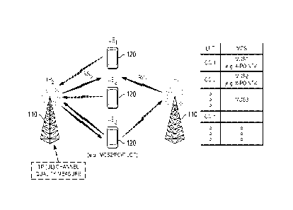
[0023]
Figure 1 shows an embodiment of LA in UL grant-less RA with TP operations.
Specifically, the TP performs UL based measurement for the UE and controls MCS
accordingly. TP1 110 can measure interference generated by UEs 120 connected
to TP1, as
well as interference caused by transmissions between UEs 120 and other TPs,
such as TP2
110. Neighboring TPs can also exchange this information with each other,
either directly or
through a third party. A TP 110 also measures the UL signal quality of the UEs
linked to, or
within a detection range of, the TP 110.The measurement can be performed,
e.g., for initial
access, sounding reference signal (SRS), or other signal quality indicators.
The TP 110 can
also measure the linked or close by UE's mobility and location. The UEs 120
are then
categorized accordingly to such measures. For instance, fast-moving UEs 120
can be
assigned a fixed MCS, e.g., QSPK, while static and/or slow moving UEs 120 are
set for the
LA scheme with changing MCS. A TP 110 also performs PC on a neighboring UE 120
based
on long-term (LT) measurements, e.g., LT UL signal quality, LT UE mobility, LT
UE
location, or others.
[0024] Additionally, the TPs 110 or a network management entity can
establish a LT
MCS look-up table (LUT). The LT MCS LUT can be generated at the TPs or by a
central
5
CA 02979089 2017-09-08
WO 2016/188489
PCT/CN2016/083805
controller at the network that forwards the LUT or its values to the TPs. The
LT MCS LUT
may include substantially fewer entries than used for short term LA. To
establish the MCS
LUT, a TP 110 estimates multiple CQI values based on PC strategy, and
associates each CQI
value with a suitable MCS. Each CQI value and its MCS can be added as an
entry, e.g., a row
.. value, in the LUT. Each entry in the LUT corresponds to an association
between a CQI value
and a MCS. This determines the strategy for selecting MCS for a UE 120 based
on its
measured CQI. During on-going communications, the TP/network uses the LUT to
select the
appropriate MCS for a UE 120 based on its measured CQI. For example, the UE
120 is
assigned MCS1 at CQI1 measured levels, and is then upgraded to MCS2 when the
CQI
.. changes from CQI1 to CQI2. With similar logic, the UE 120 can be downgraded
from MCS2
to MCS1 according to the measured changes in CQI levels. UE MCS upgrade and
downgrade
can be based on UE long-term measurement in the uplink and categorization of
the UEs
based on such measurements. For example, according to the measurement values,
the UEs
can be categorized as fast-moving (or high mobility) UEs, slow moving (or low
mobility)
UEs, or static UEs. Similarly, pilot adjustment as needed is also an option to
provide better
channel measurements at TP. The upgrade and downgrade may be achieved via TP
signaling
to the UEs 120. Radio Resource Control (RRC) signaling can be used for UE
grouping and
RA resource allocation. The signaling instructing an upgrade or downgrade may
indicate a
new MCS to switch to, the transmission power and optionally pilot reselection.
The upgrade
or downgrade of UE MCS based on the UL LT measurement may also be performed
periodically.
[0025]
Figure 2 shows an embodiment of LA in UL grant-less RA with UE operations.
A UE 120 in the wireless system obtains resource allocation information, e.g.,
via RRC
signaling, when UE power is on. During initial data access, the UE 120 can
adjust the
transmission power based on an outer loop power control (OLPC) scheme. The
packet
transmission can also be carried with the most robust MCS supported by the
system. When a
failed transmission is detected, the previous transmission is retransmitted in
accordance with
a ReTx protocol. The UE 120 can also perform MCS downgrade without signaling a
neighboring TP 110/network in scenarios such as when unexpected events occur
to the UE
120. For example, a static/slow-moving UE 120 with a higher MCS can initiate a
MCS
downgrade when the UE 120 determines that it has started to move at a faster
speed but a
neighboring or other TP 110 has no timely information of the UE. In another
example
scenario, a UE 120 with higher MCS can downgrade MCS for certain
traffic/application that
6
CA 02979089 2017-09-08
WO 2016/188489
PCT/CN2016/083805
requires higher reliability. In yet another scenario, a UE 120 with higher MCS
can go
downgrading MCS before its maximum retransmission times are reached.
[0026] Figure 3 shows an embodiment of UE RA resource allocation, which
may be
implemented with the LA scheme in UL grant-less RA. In a first implementation
option, the
HE MCS grouping is obtained by grouping the UEs 320 that share the same MCS.
The UEs
in a particular MCS grouping access the same resource, e g , same bandwidth
region or same
designated Transmission Time Interval (TTI). The RA resources are divided into
resource
block, each block defined by a frequency and time boundaries. Each resource
block can be
allocated to serving different MCS groups (e.g., MCS1, MCS2, and MCS3). Each
MCS
group includes one or more UEs 320. The UEs 320 with same MCS access the same
resource
region. The resource allocations for the UE MCS groups can be static, semi-
static or
periodically updated or upon determining that the resource allocation is
needed, e.g., based
on signal quality, UE mobility, and/or other criteria. Such an allocation
scheme can reduce
the detection/search complexity. In a second implementation option, the UEs
320 share all
the RA resources, e.g., the entire bandwidth or transmission time. In this
case, the TPs 310
have the capability to decode mixed MCSs from UEs 320 in different UE MCS
groups in a
single TTI. Such an allocation scheme can increase resource utilization.
[0027] Figure 4 shows an embodiment of PC for RA with grant-less
scheduling. The
network TPs 410 have knowledge of the location of the UEs, for instance by
measuring UE
sounding channel. The TPs 410 surrounding the UEs 420 can exchange the LT
measurements
with each other. For initial access, a UE 420 can notify the network/TP of its
maximum
transmission power and/or power headroom. UL PC criteria can then be used to
perform PC.
The criteria include achieving maximum or highest possible MCS while
minimizing potential
interference. For example, the edge UEs 420, UE1 and UE2, may have different
transmission
power when applying PC, but the same MCS due to their different interference
levels with
respect to TP2. Further, different mobility UEs 420 can be assigned different
power margins
for LA. An additional margin can also be considered for LA due to fast fading
channel
characteristics. In one PC exemplary implementation given a block error ratio
(BLER), a
number of assigned resource blocks (RBs), and predefined power offset, Ai, and
CQIi for
user i, the highest MCSj is chosen such that Interf(P(MCSj)+ Aj) <= Interf-max
and
P(MCSj)+ Aj <= Pmax, where P(MCSj) is UE transmission (Tx) power, Pmax is UE
maximum Tx power, and Interf-max is the allowable maximum interference to the
closest
neighbor.
7
CA 02979089 2017-09-08
WO 2016/188489 PCT/CN2016/083805
[0028] In the first implementation option described above for UE RA
resource allocation
based on UE MCS grouping, Sc can be configured on some TTIs and/or time-
frequency
resources with a less robust MCS, which may be suitable for sufficiently high
signal quality
levels for transmission. The configuration can be implemented in a semi-static
manner. A
retransmission protocol can also be used, where the UE performs the
retransmission with the
same MCS. The retransmission can be performed with a random back-off time, for
the same
or different content. After reaching a predefined number of maximum
retransmission times,
the MCS can be downgraded to a lower (most robust) MCS, which may be suitable
for lower
or lowest signal quality levels acceptable for transmission. The failed packet
is dropped after
the retransmissions of the same MCS and the SC retransmissions. There can be
one or more
retransmission attempts in the SC. According to this ReTx protocol, the TP
detects signals in
different MCS resource regions. The UEs in each MCS region can be detected
separately.
The UEs that are not detected in all the MCS region except the most robust MCS
(e.g., MC S1)
are detected in the SC. Chase combining (CC) or incremental redundancy (IR)
can be used in
some cases to reduce failed detection signals. If a UE can be detected
successfully, the TP
can take advantage of it to help detect other UEs. For example, successive
interference
canceller (SIC) and hybrid automatic repeat request (HARQ) combining is
possible. For
ReTx, the TP can adjust the MCS and transmission power (and optionally the
pilot) for a UE
as needed, and send the updates to the UE. The TP can also apply MCS downgrade
for failed
transmissions.
[0029] Figure 5 shows an embodiment of a ReTx protocol according to
second
implementation option described above for UE RA resources shared by all UEs.
The UE can
perform retransmission with the same MCS, as shown for UE1 and UE2 with MC S2.
The UE
can retransmit in the SC with an indication of its previous failures after it
reaches the
predefined maximum retry times in the original RA resources, as shown for UE1.
Also, the
UE can retransmit one or more times in the SC. The indication may be a
retransmission
indicator or flag. This is to distinguish the data from regular new
transmissions. The failed
packet is then dropped after all retransmissions. The SC can also be used for
new user data
transmission. As described above, the TP is able of detecting signals for
mixed MCSs. The
TP receiver searches for all users. However, in the SC, detection of only the
most robust
MCS (e.g., MCS1) is needed, as shown for UE1 retransmission. In some cases to
reduce
failed detection signals, CC or IR can be used. If one UE can be detected
successfully, the TP
can take advantage of the detected UE to help detect other UEs, for example
using SIC and
8
CA 02979089 2017-09-08
WO 2016/188489
PCT/CN2016/083805
HARQ. The TP can also adjust the MCS, transmission power, and optionally the
pilot for a
UE on demand, and send updates to the UE. The TP can also apply MCS downgrade
for
failed transmissions.
[0030] Figure 6 shows a protocol diagram of an embodiment method for TP
originated
MCS upgrade in RA. The HE starts by sending an initial data transmission or
packet to the
TP, e.g., eNB, at a TTI i (where i designates an instance in time units). The
UE then sends a
second packet at TTI i+5 (5 indicates additional time with respect to i, e.g.
5 seconds), a third
packet at TT i+12, and a fourth packet at TTi i+N (N is an integer > 12). The
packets are sent
using a robust MCS (e.g., MCS1). Upon detecting each of the packets
successfully, the
TP/eNB returns an acknowledgement (ACK) to the UE (not shown). After a number
of
successive packets are detected successfully (e.g. 4 in the illustrated
example), the TP/eNB
may determine that the signaling conditions for the UE are above a threshold
and based on
that determination, the TP can upgrade the MCS to improve efficiency (as shown
for the
transmission at TTI i+N+2). The MCS upgrade decision may be made by TP upon
satisfying
predefined good signal condition criteria. These criteria, which may include
factors such as
receiving successfully a predefined number of subsequent packets, may be
determined on a
UE to UE basis, so that only UEs demonstrating the sufficiently reliable
channels are
impacted. As illustrated in Figure 6, after being informed of the MCS upgrade,
the UE can
send a fifth transmission using the upgraded MCS (e.g., MCS2).
[0031] Figure 7 shows a protocol diagram of another embodiment method for
execution
at a TP for a TP originated MCS downgrade in RA. The HE sends a data
transmission
(illustrated as packet j) to the TP, e.g., eNB, at a TTI k (where k designates
an instance in
time units) using MCS2. This transmission is successfully detected by the
TP/eNB. The UE
then sends a second packet j+1 at TTI k+6 (e.g. 6 seconds after time instance
k) using the
.. same MCS2, and a third packet j+2 at TTI k+20 using the same MCS2, which
are both
successfully detected at the TP/eNB. Nothing in the transmissions from the UE
necessarily
indicates that a change in the MCS is warranted. However, after receiving a
number of
transmissions successfully with MCS2, the TP/eNB detects a higher UL
interference from
any UE within proximity or detection range of the TP/eNB, which leads to
channel quality
degradation. In response, the TP/eNB decides to preemptively downgrade the MCS
used by
the UE to MCS1 to avoid transmission problems. The TP sends the MCS downgrade
instruction to the UE at TTI k+32. Next, the UE sends a new packet j+3 at TTI
k+40 using
the more robust MCS1.
9
CA 02979089 2017-09-08
WO 2016/188489 PCT/CN2016/083805
[0032] Figure 8 shows a protocol diagram of an embodiment method for a
UE originated
MCS downgrade in RA. As illustrated, the UE sends a data transmission (packet
j) to the TP,
e.g., eNB, at a TTI k using MCS2. This transmission is successfully detected
by the TP/eNB.
The HE then sends a second packet j+1 at TTI k+6 (e.g. 6 seconds after time
instance k)
using the same MCS2. When this transmission fails, e.g., the UE does not
receive an ACK
response from the TP/eNB, the UE retransmits packet j+1 at TTI k+20 using
MCS2. When
this retransmission fails, again the UE does not receive an ACK from the TP.
The lack of
ACK allows the UE to determine that the transmission is unsuccessful. Upon
reaching a
predefined number of failed retransmissions, the HE changes the MCS to MCS1
and
retransmits packet j+1 at TTI k+30 using SC with MCS1. MCS1 is more robust
than MCS2.
Retransmitting the packet on the SC with MCS1, which is a more robust channel
than MCS2
or a most robust MCS, serves to trigger the MCS downgrade and indicates a
request of the
downgrade to the TP/eNB or network. Upon detecting this retransmission in the
SC (with
MCS1 by default), the TP/eNB downgrades the MCS for the HE from MCS2 to MCS1
and
sends an ACK back to the UE (not shown). A downgrade instruction (or
confirmation as the
case may be) is thus sent to the UE at TTI k+32. The UE sends a new packet j+2
at TTI k+40
using MCS1.
[0033] Figure 9 shows a protocol diagram of another embodiment method
for UE
originated MCS downgrade in RA. The UE sends a data transmission (packet j) to
the TP,
e.g., eNB, at a TTI k using MCS2, which is successfully detected by the
TP/eNB. The UE
subsequently sends a second packet j+1 at TTI k+6 using the same MCS2, which
is also
successfully detected by the TP/eNB. The UE mobility then changes its mobility
state. In the
illustrated embodiment, a slow moving UE transitions to a fast movement state.
The UE is
aware of its change in mobility and network entities may not yet be aware of
this change. The
UE transmits the next packet j+2 at TTI k+20 in the SC with the MCS1, which as
discussed
above can represent the most robust MCS available. Transmitting the packet on
the SC with
MCS1 serves to trigger the MCS downgrade and indicates a request for the
downgrade to the
TP/eNB or network. Upon receiving packet j+2 at the TP/eNB in the SC with
MCS1, the
TP/eNB is informed of the change in UE mobility or signal condition, and hence
updates the
UE category and downgrades its MCS. A downgrade instruction can be sent to the
HE. The
UE can treat this as an acceptance of the request to move to MCS1. When the UE
transmits
packet j+3 at TTI k+40 it does so using MCS1. The UE will continue
transmitting using MCS,
CA 02979089 2017-09-08
WO 2016/188489
PCT/CN2016/083805
as shown by the transmission packet j+4 at TTI k+51, until a MCS upgrade is
triggered,
typically by the TP or other network entity.
[0034] In other embodiments, a UE can initiate an MCS downgrade after
detecting a LA
condition associated with the UE transmission qualities and application QoS.
For instance,
the UE downgrades the MCS when more reliable transmission is needed for a
traffic
application. In an example, the HE initiates the MCS downgrade upon
determining a quality
of service (QoS) requirement for an application of the UE that requires a more
robust MCS.
[0035] In further embodiments, one of the entities participating in the
grant free wireless
communication uses a Modulation and Coding Scheme (MCS) to transmit data. The
node
may be a UE or a TP that initiates a change in MCS based on a non-link factor.
For instance,
the non-link factor can be the determination of mobility (move) or change in
mobility of the
UE, a launch of an application of the UE, a foreknowledge of an expected or
likely change in
channel characteristics, or other factors that require change of MCS, e.g., to
a more robust
MCS, that may not be associated with link conditions between the UE and TP.
When the
node (UE or TP) determines according to the non-link based factor that a new
MCS should be
used in place of a current MCS (e.g., the new MCS is more robust than the
current MCS), the
node instructs a grant free transmission controller to use the new MCS for
subsequent grant
free transmissions. In the case of UE initiated MCS change, the instructed
grant free
transmission controller may be a local controller at the UE. In the case of TP
initiated MCS
.. change, the instruction can be sent from the TP to a UE controller.
[0036] Figure 10 is a block diagram of a processing system 1000 that can
be used to
implement various embodiments. The processing system 1000 can be part of a TP
or eNB, a
TIE, or other network devices Specific devices may utilize all of the
components shown, or
only a subset of the components, and levels of integration may vary from
device to device.
Furthermore, a device may contain multiple instances of a component, such as
multiple
processing units, processors, memories, transmitters, receivers, etc. The
processing system
1000 may comprise a processing unit 1001 equipped with one or more
input/output devices,
such as a speaker, microphone, mouse, touchscreen, keypad, keyboard, printer,
display, and
the like. The processing unit 1001 may include a central processing unit (CPU)
1010, a
memory 1020, a mass storage device 1030, a video adapter 1040, and an I/O
interface 1060
connected to a bus. The bus may be one or more of any type of several bus
architectures
including a memory bus or memory controller, a peripheral bus, a video bus, or
the like.
11
CA 02979089 2017-09-08
WO 2016/188489 PCT/CN2016/083805
[0037] The CPU 1010 may comprise any type of electronic data processor.
The memory
1020 may comprise any type of system memory such as static random access
memory
(SRAM), dynamic random access memory (DRAM), synchronous DRAM (SDRAM), read-
only memory (ROM), a combination thereof, or the like. In an embodiment, the
memory
1020 may include ROM for use at boot-up, and DRAM for program and data storage
for use
while executing programs. In embodiments, the memory 1020 is non-transitory.
The mass
storage device 1030 may comprise any type of storage device configured to
store data,
programs, and other information and to make the data, programs, and other
information
accessible via the bus. The mass storage device 1030 may comprise, for
example, one or
more of a solid state drive, hard disk drive, a magnetic disk drive, an
optical disk drive, or the
like.
[0038] The video adapter 1040 and the I/O interface 1060 provide
interfaces to couple
external input and output devices to the processing unit. As illustrated,
examples of input and
output devices include a display 1090 coupled to the video adapter 1040 and
any combination
of mouse/keyboard/printer 1070 coupled to the I/O interface 1060. Other
devices may be
coupled to the processing unit 1001, and additional or fewer interface cards
may be utilized.
For example, a serial interface card (not shown) may be used to provide a
serial interface for
a printer.
[0039] The processing unit 1001 also includes one or more network
interfaces 1050,
which may comprise wired links, such as an Ethernet cable or the like, and/or
wireless links
to access nodes or one or more networks 1080. The network interface 1050
allows the
processing unit 1001 to communicate with remote units via the networks 1080.
For example,
the network interface 1050 may provide wireless communication via one or more
transmitters/transmit antennas and one or more receivers/receive antennas. In
an embodiment,
the processing unit 1001 is coupled to a local-area network or a wide-area
network for data
processing and communications with remote devices, such as other processing
units, the
Internet, remote storage facilities, or the like.
[0040] While several embodiments have been provided in the present
disclosure, it
should be understood that the disclosed systems and methods might be embodied
in many
other specific forms without departing from the spirit or scope of the present
disclosure. The
present examples are to be considered as illustrative and not restrictive, and
the intention is
not to be limited to the details given herein. For example, the various
elements or
12
CA 02979089 2017-09-08
WO 2016/188489
PCT/CN2016/083805
components may be combined or integrated in another system or certain features
may be
omitted, or not implemented.
[0041] In addition, techniques, systems, subsystems, and methods
described and
illustrated in the various embodiments as discrete or separate may be combined
or integrated
with other systems, modules, techniques, or methods without departing from the
scope of the
present disclosure Other items shown or discussed as coupled or directly
coupled or
communicating with each other may be indirectly coupled or communicating
through some
interface, device, or intermediate component whether electrically,
mechanically, or otherwise
Other examples of changes, substitutions, and alterations are ascertainable by
one skilled in
the art and could be made without departing from the spirit and scope
disclosed herein.
13