Note: Descriptions are shown in the official language in which they were submitted.
CA 02979331 2017-09-11
WO 2016/178694 PCT/US2015/029741
RAPID SWITCHING DUAL PROPPANT DELIVERY SYSTEM
TECHNICAL FIELD
The present disclosure relates generally to transferring solid or liquid bulk
materials for well
operations, and more particularly, to a rapid switching dual proppant delivery
system.
BACKGROUND
During the drilling and completion of oil and gas wells, various wellbore
treating fluids are
used for a number of purposes. For example, high viscosity gels and proppant
infused liquids are
used to create fractures in oil and gas bearing formations to increase
production. High viscosity and
high density gels are also used to maintain positive hydrostatic pressure in
the well while limiting
flow of well fluids into earth formations during installation of completion
equipment. High
viscosity fluids are used to flow sand into wells during gravel packing
operations. The high
viscosity fluids are normally produced by mixing dry powder and/or granular
materials and agents
with water at the well site as they are needed for the particular treatment.
Systems for metering and
mixing the various materials are normally portable, e.g., skid- or truck-
mounted, since they are
needed for only short periods of time at a well site.
The powder or granular treating material is normally transported to a well
site in a
commercial or common carrier tank truck. Once the tank truck and mixing system
are at the well
site, the dry powder material (bulk material) must be transferred or conveyed
from the tank truck
into a supply tank for metering into a blender as needed. The bulk material is
usually transferred
from the tank truck pneumatically. More specifically, the bulk material is
blown pneumatically
from the tank truck into an on-location storage/delivery system (e.g., silo).
The storage/delivery
system may then deliver the bulk material onto a conveyor or into a hopper,
which meters the bulk
material through a chute into a blender tub.
The pneumatic conveying process used to deliver bulk material from the tank
truck can be a
time-consuming process. In addition, some well locations are arranged without
a large amount of
space to accommodate tank trucks, such that only a limited number of available
tank trucks can be
positioned to pneumatically fill the storage/delivery system at a given time.
Accordingly, the
pneumatic conveying process can lead to dead time of equipment usage and
relatively high
detention costs or demurrage costs associated with the tank trucks, hoses, and
related equipment that
1
CA 02979331 2017-09-11
WO 2016/178694 PCT/US2015/029741
are on-location during this time.
Furthermore, during the pneumatic conveying process, the bulk material is
moved from the
tank truck to the storage/delivery system in a turbulent manner, leading to
large amounts of dust and
noise generation. The air used for conveying the material must be vented from
the storage tank and
typically carries an undesirable amount of dust with it. Attempts to control
dust during the
conveying process typically involve the rig up and use of auxiliary equipment,
such as a dust
collector and ductwork, adding cost and operator time to the material handling
operations.
In addition, traditional material handling systems can have several transfer
points between
the outlets of multiple storage/delivery systems and a blender. These transfer
points often have to be
shrouded and ventilated to prevent an undesirable release of dust into the
environment. Further,
after the dust has been captured using the dust collectors and ventilation
systems, additional steps
are needed to dispose of the dust.
BRIEF DESCRIPTION OF THE DRAWINGS
For a more complete understanding of the present disclosure and its features
and advantages,
reference is now made to the following description, taken in conjunction with
the accompanying
drawings, in which:
FIG. 1 is a schematic block diagram of a bulk material handling system
suitable for
delivering a container of bulk additive materials to a blender receptacle
(e.g., blender tub or hopper)
for mixing with liquids to form well treating fluids at a well site, in
accordance with one
embodiment of the present disclosure;
FIG. 2 is a schematic block diagram of a bulk material handling system
suitable for
delivering two containers of the same or different bulk additive materials
simultaneously to a
blender receptacle (e.g., blender tub or hopper) for mixing with liquids to
form well treating fluids at
a well site, in accordance with another embodiment of the present disclosure;
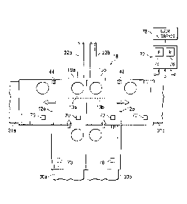
FIG. 3 is a schematic top view of a two-container bulk delivery system in a
side-by-side
orientation over a hopper and an associated metering mechanism connected
thereto and a container
delivery management system which interfaces therewith, in accordance with the
embodiment
illustrated in FIG. 2;
FIG. 4 is a schematic side view the container, hopper and associated metering
mechanism
2
CA 02979331 2017-09-11
WO 2016/178694 PCT/US2015/029741
shown in FIG. 3; and
FIG. 5 is a side view of an alternate embodiment of the container, hopper and
associated
metering mechanism shown in FIG. 3, which incorporates a funnel to further
direct the bulk material
into the hopper.
FIG. 6 is a schematic diagram of an alternate embodiment illustrating a
container stack
delivering bulk material to a pair of storage silos.
DETAILED DESCRIPTION
Illustrative embodiments of the present disclosure are described in detail
herein. In the
interest of clarity, not all features of an actual implementation are
described in this specification. It
will of course be appreciated that in the development of any such actual
embodiment, numerous
implementation specific decisions must be made to achieve developers' specific
goals, such as
compliance with system related and business related constraints, which will
vary from one
implementation to another. Moreover, it will be appreciated that such a
development effort might be
complex and time consuming, but would nevertheless be a routine undertaking
for those of ordinary
skill in the art having the benefit of the present disclosure. Furthermore, in
no way should the
following examples be read to limit, or define, the scope of the disclosure.
Certain embodiments according to the present disclosure may be directed to
systems and
methods for managing bulk material (e.g., bulk solid or liquid material used
on location) efficiently
at a well site. More specifically, the disclosed embodiments are directed to
systems and methods for
efficiently moving bulk material into a blender receptacle associated with a
blender on location,
which could be into a blender hopper or directly into a mixing tub of the
blender. The present
disclosure may include a system that utilizes multiple containers (e.g., pre-
filled containers or filled
on location) holding bulk material and positioned to transfer bulk material
from the containers
directly into the blender receptacle. The disclosed techniques may be used to
efficiently handle any
desirable bulk material having a solid or liquid constituency including, but
not limited to, sand,
proppant, gel particulate, dry-gel particulate, liquid additives, and others.
In currently existing on-site bulk material handling applications, bulk
material (e.g., sand,
proppant, gel particulate, or dry-gel particulate) may be used during the
formation of treatment
fluids. In such applications, the bulk material is transferred between
transportation units, storage
3
CA 02979331 2017-09-11
WO 2016/178694 PCT/US2015/029741
tanks, blenders, and other on-site components. The bulk material is often
transferred pneumatically
using pressurized airflows to provide the bulk material, for example, from a
transportation unit (e.g.,
tank truck) to a storage/delivery system (e.g., silo). The bulk material may
later be moved from the
storage/delivery system to a hopper on a blender truck. A sand screw, chute,
or other metering
mechanism disposed in the hopper then meters the bulk material into a blender
tub of the blender,
where the bulk material is mixed with other materials (e.g., water, fluids,
chemicals, etc.). In some
instances, the bulk material can be transferred pneumatically from a
transportation unit into a
storage tank on the blender truck.
Pneumatic transfer methods are generally selected due to the simplicity of the
process.
However, certain inherent inefficiencies are associated with the above-
described pneumatic transfer
of bulk material at a well site. First, blowing the bulk material
pneumatically from a transportation
unit to a storage/delivery system is a time consuming process, taking at least
an hour to empty a
single truck. Although the pneumatic process of blowing bulk material into a
storage container can
be .accomplished prior to using the bulk material in blender operations, the
long amount of time
spent pneumatically transferring the bulk material to the storage/delivery
system can lead to high
equipment/detention costs. Detention costs are associated with the
transportation equipment (e.g.,
tank trucks) being positioned on location for a period of time. In some
instances, the equipment on
location may be arranged so that accessibility to storage/delivery systems is
limited for
transportation units being used to pneumatically fill the storage/delivery
systems. As a result, a
large amount of time can be wasted by trucks waiting to move into position as
other trucks are
unloading bulk material, or trucks waiting for the material already in a
storage bin to be used to
make room for the next load of material.
In addition, the pneumatic transfer of bulk material tends to require a large
amount of air to
move the material through the system. As this volume of air vents to the
atmosphere, fine dust
particles are entrained and released. It is undesirable for this dust to be
released into the atmosphere.
Accordingly, existing systems employ dust control techniques that often
utilize large pieces of
additional equipment, separate power supplies, and complicated setups. In
addition, the pneumatic
transfer process, as well as the systems used to control dust, can lead to an
undesirable level of noise
produced during bulk material transfer.
The bulk material container systems disclosed herein are designed to address
and eliminate
4
CA 02979331 2017-09-11
WO 2016/178694 PCT/US2015/029741
these shortcomings. The presently disclosed techniques use a plurality of
linearly arranged
containers, instead of a pneumatic transfer process, to move the bulk material
from a transportation
unit(s) to the blender receptacle (e.g., blender hopper or mixer). The
transportation unit may deliver
one or more containers full of bulk material to the well site, where the
containers may then be
aligned linearly and/or side-by-side over the blender receptacle. The
containers may be positioned
such that a container stack is disposed immediately above a pair of hoppers
which deliver the two
different types of material to a pair of associated silos for storage of
different compositions of bulk
material or such that two or more containers are arranged side-by-side each
other immediately above
a divided chamber hopper or associated pair of hoppers, which delivers the
bulk material to the
receptacle of the blender. The bulk material may be dispensed directly from
the container(s) into the
receptacle (e.g., via a chute, hatch, opening, etc.). A gravity feed outlet or
chute may extend from
the bottom of the containers, to route bulk material from the one or more
containers directly into the
blender receptacle. Since the transportation unit is able to unload the
container stack or side-by-side
arranged containers of bulk material without pneumatic transfer, the
containers may be used to more
efficiently transfer bulk material to the blender.
The container systems and methods described herein may reduce detention costs
associated
with bulk material handling at the location, since the efficient filling
process may enable a quicker
offloading of each tank truck, as compared to those that rely on pneumatic
transfer. In addition, by
eliminating the pneumatic conveyance process entirely, the stacked/side-by-
side arranged container
system may reduce the amount of dust generated at the location, as well as the
noise levels
associated with the bulk material transfer. The reduced dust generation may
allow a reduction in the
size of various dust control equipment used to ventilate the material handling
system, leading to a
reduction in overall cost, footprint, and rig-up time of the dust control
equipment.
Turning now to the drawings, FIG. 1 is a block diagram of a bulk material
handling system
10. The system 10 includes a plurality of containers 12, each designed for
holding a quantity of
bulk material (e.g., solid or liquid treating material). The containers 12 may
utilize a gravity feed to
provide a controlled, i.e., metered, flow of bulk material at an outlet 14.
The outlet 14 may be a
chute that conveys the bulk material from the containers 12 to a blender 16.
As illustrated, the
blender 16 may include a hopper 18 and a mixer 20 (e.g., mixing compartment).
The blender 16
may also include a metering mechanism 22 (e.g., sand screw) for providing a
controlled, i.e.,
5
CA 02979331 2017-09-11
WO 2016/178694 PCT/US2015/029741
metered, flow of bulk material from the hopper 18 to the mixer 20. However, in
other embodiments
the blender 16 may not include the hopper 18, such that the outlet 14 from the
containers 12 may
provide bulk material directly into the mixer 20.
All such embodiments are intended to be
encompassed by the present disclosure.
Water and other additives may be supplied to the mixer 20 (e.g., mixing
compartment)
through inlets 24 and 25, respectively. The bulk material and liquid additives
may be mixed in the
mixer 20 to produce (at an outlet 26) a fracturing fluid, gel, cement slurry,
drilling mud, or any other
fluid mixture for use on location. The outlet 26 may be coupled to a pump for
conveying the
treating fluid down hole into a well (e.g., a hydrocarbon recovery well) for a
treating process. It
should be noted that the disclosed container 12 may be utilized to provide
bulk material for use in a
variety of treating processes. For example, the disclosed systems and methods
may be utilized to
provide proppant materials into fracture treatments performed on a hydrocarbon
recovery well. In
other embodiments, the disclosed techniques may be used to provide other
materials (e.g., non-
proppant) for diversions, conductor-frac applications, cement mixing, drilling
mud mixing, and
other fluid mixing applications.
The containers 12 may be positioned in a side-by-side arrangement as
illustrated in FIG. 2
with containers 12a and 12b. The containers 12 may be replaceable such that
once the bulk material
from one container 12 runs low, the empty container is moved off conveyor 30
and placed on a
transportation unit (e.g, truck) 32, which carries away the empty containers
for subsequent refilling
offsite. Transportation unit(s) 34 is provided for delivering full containers
12 on one end of the
conveyor 30, while transportation unit 32 is provided at the other end for
receiving the empty
containers. The transportation units 32, 34 can continuously supply containers
12 full of bulk
material via the conveyor 30 to the blender 16, such that a continuous supply
of bulk material is
delivered to the blender 16.
As shown in FIG. 2, the two conveyors 30a and 30b may be positioned side-by-
side over the
blender 16 so that two containers 12a and 12b may be placed over the blender
at a time. This
arrangement can double the rate at which bulk material is being delivered to
the blender 16. Each
container 12a and 12b may hold the same type, particle size, and/or material
of bulk material in
some embodiments. In other embodiments, the containers 12a and 12b may hold
different types,
particle sizes, and/or materials of bulk material, to provide a desired
treating fluid for the treating
6
CA 02979331 2017-09-11
WO 2016/178694 PCT/US2015/029741
process being performed. For example, when performing fracturing operations,
it may be desirable
to initially pump a treating fluid having smaller proppant particles down
hole, to start opening
perforations formed within the well. After this, the fracturing treatment may
proceed to pumping a
treating fluid with large proppant particles down hole, to expand the openings
in the perforations.
The large proppant particles may be supplied from one container (e.g., forward
container 12b) after
the smaller proppant particles are used from the other container (e.g., rear
container 12a). As those
of ordinary skill in the art will appreciate, while only two conveyors 30a and
30b are shown
disposed side-by-side over the blender 16, additional conveyors carrying
additional containers may
be arranged over the blender 16.
Transportation units 34 may be provided at the well site for storing one or
more additional
containers 12 of bulk material to be used at the site. Multiple transportation
units 34 may act as a
bulk storage system at the well site for holding large quantities of
containers in reserve for use at the
well. Before a treatment begins, one or more containers 12 of bulk material
may be transferred from
the transportation units 34 to conveyors 30a and 30b, as indicated by the
arrow 40. This transfer
may be performed by lifting the container 28 via a hoisting mechanism, such as
a forklift or a crane
or by sliding the containers off the back of the transportation units 34
directly onto the conveyors
30a and 30b via wheels attached to the containers 12 or the platform of the
transportation units 34.
Alternatively, the transportation units 34 themselves may be equipped with
their own conveyors
thereby permitting conveyor-to-conveyor transfer of the containers 12 from the
transportation units
34 to the conveyors 30.
After one or more of the containers 12a and 12b on the conveyors 30a and 30b
are emptied,
the empty container(s) may be removed by advancing the conveyor(s) so as to
move the empty
container(s) to an empty transportation unit 32 used to haul the empty
containers 12 away. In some
embodiments, the one or more empty containers 12 may be positioned on a skid,
a pallet, or some
other -holding area until they can be removed from the well site and/or
refilled. In other
embodiments, the one or more empty containers 12 may be positioned directly
onto the empty
transportation unit 32 for transporting the empty containers 12 away from the
well site as shown by
arrow 42. It should be noted that the same transportation unit 34 used to
provide one or more filled
containers 12 to the well site may then be utilized to remove one or more
empty containers from the
well site, i.e., serve as transportation unit 32.
7
CA 02979331 2017-09-11
WO 2016/178694 PCT/US2015/029741
FIG. 3 shows an enlarged view of an embodiment where the containers 12a and
12b are
disposed over a hopper 18 in the side-by-side configuration. The hopper 18 may
be divided into two
separate compartments 18a and 18b so that, if desired, different compositions
of bulk material may
be fed into the blender. Alternatively, separate hoppers may be utilized. Each
of the compartments
I 8a and 18b are connected to associated metering mechanisms 22a and 22b,
which transport the
bulk material from the hopper 18 into the mixer 20. In this embodiment, given
the generally narrow
width of the hopper 18, the containers 12a and 12b are provided with openings
13a and 13b on one
side of their bottom, desirably at one corner, so that the containers may be
arranged on the
conveyors 30a and 30b so that the openings 13a and 13b are juxtaposed adjacent
to one another. It
should be noted that a similar arrangement of containers 12a and 12b may be
used in other
embodiments to deliver bulk material from the containers 12a and 12b directly
into the mixer of the
blender, without using a hopper.
In some embodiments, each container 12 when filled to maximum capacity may
hold
approximately one small tank truckload of bulk material. To accommodate this
amount of bulk
material capacity, each of the containers 12 may have an internal volume of up
to approximately 14
cubic meters for holding bulk material. In other embodiments, however, the
containers 12 may hold
a smaller or larger amount of bulk material than a tank truck.
Each of the containers 12 disposed above the blender 16 may provide a gravity
feed of bulk
material into the blender 16 (and optionally via the hopper 18). That is, the
bulk material is moved
from the containers 12 into the blender/hopper via gravity, instead of on a
conveyor. This may keep
the bulk material from generating a large amount of dust, since the bulk
material is flowing into the
blender/hopper instead of falling into the blender/hopper (which would cause
air entrainment of the
dust) as more capacity within the blender receptacle becomes available.
As shown in FIG. 4, the containers 12 may utilize a choke feed to meter the
bulk material
into the hopper 18 (or alternatively, directly into the mixer of the blender).
This is accomplished
with the aid of a chute 50, which is attached at the bottom of the container
12 through the openings
13. When an outlet valve or dumping mechanism on the containers 12 are
actuated, the top of the
chutes 50 may be opened and kept open while the chutes fill the hopper 18. The
bulk material may
travel down the chutes 50 and be discharged into the hopper 18 under a force
due to gravity working
on the bulk material. The chute 50 extends down into the hopper 18 such that
the bottom of the
8
CA 02979331 2017-09-11
WO 2016/178694 PCT/US2015/029741
chute is below the top edge of the hopper 18. This configuration enables the
desired choke feeding
to be accomplished. An additional aspect of this embodiment is that the
conveyors 30 are open at
the bottom so as to permit the flow of bulk material through the bottom of the
conveyors 30 into the
hopper 18.
In the illustrated embodiment, the containers 12a are labeled as holding a
first type, particle
size, or material of bulk material (A), while the containers 12b are labeled
as holding a second type,
particle size, or composition of bulk material (B). The bulk material A may be
the same or different
from the bulk material B. As the container 12a outputs the bulk material A
into the hopper 18, the
bulk material B may be dispensed from container 12b into the hopper 18 via
chute 50b.
Alternatively, the flow of bulk material B may follow the flow of bulk
material A where the type,
particle size or composition of bulk material B is different from bulk
material A and it is desired to
have different treatment fluids entering the well bore at any given time. Once
all the bulk material
A is dispensed from the container 12a into the hopper 18, another container
12a is delivered along
conveyor 30a to the dispensing region 54, which is located just above the top
of the hopper 18. The
conveyors 30 are designed such that the bulk material is permitted to fall out
of the containers 12
into the hopper 18. Accordingly, in at least one embodiment therefore, they
are formed by a pair of
parallel open rails in the dispensing region 54. In such an embodiment, the
containers 12 are at least
formed of rails at their bottom surface, which can ride along the rails
forming the conveyor.
Structures such as wheels can incorporated either into the rails of the
conveyor 30 or the rails on the
containers 12 or both in such an embodiment. As those of ordinary skill in the
art will appreciate,
other configurations of the conveyors 30 and containers 12 may be employed to
enable the
containers to move laterally while at the same time dispense their load into
the hopper 18.
It may be desirable, in some instances, to arrange the containers 12 in a
desired order so that
a desired bulk material is provided to hopper 18 at a certain time. Also, it
may be desirable to
arrange the containers 12 so that they are all designed to output the same
bulk material into the
hopper 18 at the same time.
Arranging the containers 12 along one or more parallel conveyors 30 may enable
a more
efficient use of space at the well site. This arrangement may also enable the
transportation units 32,
34 to more efficiently maneuver through the well site, as they only need to
park on two sides of the
hopper 18 to provide new containers 12 to receive empty containers that are
being removed from the
9
CA 02979331 2017-09-11
WO 2016/178694 PCT/US2015/029741
conveyors 30.
The containers 12 are desirably shaped such that the bulk material is funneled
downward
under gravity to the openings 13. This may be accomplished using a variety of
different shapes.
One such exemplary shape is shown in FIG. 4, wherein main storage area of the
containers 12 has a
downwardly tapering shape. Other similar shapes may be used, e.g., a conical
shape. The other
dimensions of the containers 12 may be squared (as shown in Figs 1-4), rounded
(not shown),
cylindrical, oblong, oval, slightly bowed, or any other desirable shape. The
containers 12 may be a
"dump" type of container with one or more hatches at the bottom designed to
automatically open in
a manner that dumps the bulk material out of the container 12.
A conically shaped funnel 60 may also be employed to further direct the bulk
material from
the containers 12 to the blender/hopper, as shown in FIG. 5. A chute 62 helps
facilitate the transfer
of the bulk material from the funnel 60 to the hopper 18. The bottom of the
chute 62 is desirably
disposed below the top of the hopper 18 to allow the bulk material to be choke
feed into the hopper
18.
In some embodiments, the containers 12 may be partially or fully enclosed to
guard the bulk
material against the elements (e.g., sun, rain, and other weather). The
containers 12 may be
equipped with additional sidewalls disposed around the internal volume of the
containers 12, for
aesthetic reasons as well as to enable easier cleanup after the container 12
is emptied and removed
from the conveyors 20. That is, any dust generated from within the internal
volume of the container
12 may be contained within the additional sidewalls and enclosed portions and
then subsequently
removed or filtered, to prevent undesirable dust accumulation outside the
container 12. In some
embodiments, the containers 12 rnay be constructed with one or more coupling
mechanisms (e.g.,
hooks, latches, slots) to enable engagement between the container 12 and a
hoisting mechanism
(e.g., crane, forklift, etc.) used to handle movement of the container 12.
Bulk material inventory tracking may be generally desired at the well site. As
shown in FIG.
3, such bulk material inventory tracking may be accomplished through a number
of different sensors
70 disposed about the well site. These sensors 70 may be communicatively
coupled to one or more
controllers 72 (e.g., automated control system), which utilize at least a
processor component 74 and
a memory component 76 to monitor and/or control inventory at the well site.
For example, one or
more processor components 74 may be designed to execute instructions encoded
into the one or
CA 02979331 2017-09-11
WO 2016/178694 PCT/US2015/029741
more memory components 76. Upon executing these instructions, the processors
74 may provide
passive logging of the amount, type, and location of certain bulk materials at
the well site. In some
embodiments, the one or more processors 74 may execute instructions for
controlling the amount,
type, and location of bulk materials that are being transported about the well
site. For example, the
processors 74 may output signals at a user interface 78 for instructing
operators to remove an empty
container 12 from a conveyor 30 and replace the container 12 with a new
container 12 holding a
certain type of bulk material needed for the well treatment. Other types of
instructions for inventory
control/monitoring may be provided through the disclosed systems.
As noted above, the inventory control system 72 may include a number of
different sensors
70. In some embodiments, these sensors 70 may include one or more load cells
or bin full switches
for tracking a level of bulk material in a container 12 and indicating whether
a container 12 is
empty, full, or partially full. Such sensors 70 may be used for any given
container 12, the hopper
18, a silo, or any other component at the well site. In addition, in some
embodiments the sensors 70
may include RFID tags used to provide an indication of the particle size, bulk
volume, weight, type,
material, and/or supplier of the bulk 'Material disposed in a certain
container 12. In such instances,
the controller 72 may be communicatively coupled to an RFID reader disposed in
proximity to the
containers 12 being moved about the well site.
In some embodiments, the containers 12 may include one or more electronic
sensors 70 used
to determine and indicate whether the container 12 is full or empty. As noted
above, such electronic
sensors 70 may be communicatively coupled (e.g., wirelessly) to an automated
control system 72.
The sensors 70 may instruct the system 10 or operators to proceed to the next
available container
when an "empty" or "nearly empty" signal is detected. In other embodiments,
the containers 12
may be equipped with a mechanical sensor or mechanical indicator for
indicating whether the
container 12 is full or empty.
It may be particularly desirable for the containers 12 of Figs. 2 and 3 to be
equipped with
sensors 70 for detecting whether the container are full or empty. Once one of
the containers 12
empty, an operator may receive an instruction from the automated control
system 72 to remove and
replace the empty container 12 with a new, full container. By constantly
monitoring the level of the
containers 12, the system and ensure that the hopper 18 is receiving a near
continuous stream of
bulk material from both containers. This additional bulk material capacity may
enable the well
11
CA 02979331 2017-09-11
WO 1016/178694 PCT/US2015/029741
treatment operations to continue as desired while operators are reloading the
conveyors 30 with full
containers 12.
The side-by-side embodiment disclosed in FIG. 3 further includes a pair of
perpendicularly
disclosed conveyors 31a and 31b, which join with conveyors 30a and 30b
respectively to enable
removal of empty containers 12 through a different pathway from which the full
containers 12
entered the bulk delivery region. This design enables easy delivery and
removal of the containers 12
into the bulk delivery region. Although not shown in FIG. 3, full containers
may be delivered to via
transport units 32 and removed via transport units 34, as shown in FIG. 2.
Transfer of the containers
from conveyors 30a and 30b to the conveyors 31a and 31b may be accomplished
via bi-directional
rollers 44, as shown in FIG. 3.
As described above, the disclosed system utilizes several relatively small,
independent
containers 12 to hold the bulk material needed for a well treatment, instead
of a pneumatically filled
silo. This arrangement of individual containers 12 may provide relatively easy
methods for
transporting the bulk material around the well site. For example, the
containers 12 may enable
quick unloading of a transportation unit and quick loading/re-loading of the
conveyors 30 using a
forklift, conveyor on the transportation unit, or other moving or hoisting
mechanism. This type of
unloading/loading may be accomplished more efficiently than a pneumatic
loading process. In
addition, the containers 12 may be quickly pushed out of the way and removed
from the conveyors
30 once emptied. The smaller volumes of bulk material provided in the
containers 12 may enable a
relatively rapid change of the type of bulk material delivered to the hopper
18, allowing for quick
customization of the well treatment. The multiple containers 12 (particularly
when arranged in
parallel tracks 30a and 30b feeding into the same hopper 18) may provide a
buffer for bulk material
delivery so that the hopper 18 is constantly being supplied with bulk material
while transportation
units are arriving and being unloaded at the well site. Furthermore, once the
treatments are
completed at the well site, any remainder of filled containers 12 may be
easily transported off
location.
By making the bulk material unloading/loading process on location more
efficient, the
disclosed techniques may reduce the detention costs accrued at the well site,
since transportation
units may be able to unload their materials faster than would be possible
using pneumatics. In
addition, the disclosed techniques may enable the transfer of bulk material on
location without
12
CA 02979331 2017-09-11
WO 2016/178694 PCT/US2015/029741
generating excessive noise that would otherwise be produced through a
pneumatic loading process.
Still further, the bulk material remains in the individual containers 12 until
it is output directly into
the hopper 18 via the corresponding chutes 52. Since the bulk material remains
in the containers 12,
instead of being released directly onto a conveyor, the containers 12 may
enable movement of bulk
material on location without generating a large amount of dust.
In an alternate embodiment, the containers 12a and 12b may be arranged in a
stacked
configuration 100, as shown in FIG. 6. The container stack 100 unloads the
bulk material into a pair
of fill hoppers 102 and 104. A pair of bucket elevators or bucket lifts 106
and 108 may be provided
to transfer the bulk material from the fill hoppers 102 and 104 into the silos
110 and 112. The
containers 12a and 12b are arranged such that the bulk material in container
12a may be emptied
into container 12b such that once the bulk material from container 12a is
emptied into container 12b,
a new container 12a may be removed and positioned on top of container 12b to
maintain a steady
flow of bulk material through the bucket conveyor system 106, 108 and into the
silos 110, 112. The
silos 110, 112 may be utilized to hold a large amount of bulk material and to
output a steady flow of
bulk material to the blender 16 for forming the treating fluid when needed.
Each container I 2a and 12b may hold the same type, particulate size, and/or
composition of
bulk material in some embodiments. In other embodiments, the containers 12a
and 12b used to fill
the silos 110, 112 may hold different types, particulate sizes, and/or
compositions of bulk material,
to provide a desired treating fluid for the treating process being performed.
In such embodiments,
the material in container 12a would not be emptied into container 12b, but
rather would be emptied
directly into fill hopper 102. The contents in fin hopper 12b would
respectively be emptied into fill
hopper 104, such that silo 110 could store one bulk material A and silo 112
could store another bulk
material B. For example, when performing fracturing operations, it may be
desirable to initially
pump a treating fluid having smaller proppant particles downhole (e.g., Bulk
Material A) to start
opening perforations formed within the well. After this, the fracturing
treatment may proceed to
pumping a treating fluid with large proppant particles downhole (e.g., Bulk
Material B) to expand
the openings in the perforations. The large proppant particles may be supplied
from one container
12a after the smaller proppant particles are used from another container 12b.
As mentioned above, the silos 110, 112 may also include the bucket conveyor
systems
having bucket lifts 106, 108 used in combination with fill hoppers 102, 104,
respectively, to deliver
13
CA 02979331 2017-09-11
WO 2016/178694 PCT/US2015/029741
bulk material into an internal storage volume of the silos 110, 112. The
bucket lifts 106, 108 are
generally a lift that uses multiple scoop-shaped components disposed along the
lift to capture and
transport the bulk material upward. As each scoop-shaped component (i.e.,
bucket) passes through
the fill hoppers 102, 104 the buckets may scoop a certain amount of bulk
material out of the fill
hoppers, and the lift carries the filled buckets up toward the top of the
silos 110, 112. From here, the
buckets may be rotated downward to release the bulk material from the buckets
into an internal
storage volume of the silos 110, 112. In the illustrated embodiment, the
buckets used to transport
bulk material within the bucket lifts 106, 108 may be housed in enclosures
(e.g., tubular enclosure)
to reduce or eliminate an amount of dust released from the bucket lifts 106,
108 into the atmosphere.
In some embodiments, the bucket lifts 106, 108 and fill hoppers 102, 104 may
be built into
or integral with the silos 110, 112. In other embodiments, the bucket lifts
106, 108 may be a
separate component from the silos 110, 112. Independent bucket lifts 110, 112
(i.e., those that are
made separately and later attached to the silos 110, 112) may be manufactured
for use with a
particular storage silos 110, 112. The bucket lifts 106, 108 may be an
inclined or angled lift in some
embodiments.
The containers 12a and 12b shown in the embodiment of FIG. 6 may utilize a
choke-feed
mode to meter the bulk material from the emptying of the bulk material from
the container 12a into
container 12b and also from the emptying of the container 12b into the fill
hoppers 102 and 104 (or
alternatively from the containers 12a and 12b into the hoppers 102 and 104,
respectively). Once a
pile of bulk material is established within the fill hoppers 102, 104 (or
within container 12b), this
pile may regulate the amount of bulk material that can be directed from the
container 12b into the
fill hoppers 102, 104 (or from the container 12a into the container 12b).
Furthermore, the containers 12a and 12b shown in the embodiment of FIG. 6 may
utilize the
bulk material inventory tracking shown in FIG. 3. Thus, the sensors 70 may be
integrated into the
containers 12 and the controller 72 and user interface 78 may also be employed
in this embodiment
in the same way it is described as being employed in the embodiment shown and
described in FIG.
3.
Although the present disclosure and its advantages have been described in
detail, it should be
understood that various changes, substitutions and alterations can be made
herein without departing
from the spirit and scope of the disclosure as defined by the following
claims.
14